Drone Mounted LiDAR for Small UAVs: How to Choose a Lightweight, Budget-Friendly 3D Sensing Module
Drone mounted LiDAR has a reputation for being expensive, heavy, and tied to survey-grade GNSS/INS hardware. That reputation is fair if you are talking about professional airborne mapping payloads. But here’s the deal: not every UAV project needs a full mapping rig. A small drone used for inspection, robotics research, altitude sensing, or obstacle avoidance usually needs something much more practical — real-time 3D sensing that does not punish the aircraft’s payload, battery, budget, or integration schedule.
This guide walks through how to choose a lightweight, budget-friendly LiDAR module for drone mounting, especially when the goal is short-range 3D perception instead of survey-grade topographic mapping. We will cover how drone LiDAR works, which specifications actually matter on small UAVs, where solid-state dToF sensing fits, and how a compact module such as the DTOF Solid State LiDAR HM-LD1 can support altitude sensing, obstacle avoidance, terrain following, embedded 3D vision development, and robotics research.
Table of Contents
- 👉 What Is Drone Mounted LiDAR?
- 👉 Survey-Grade UAV LiDAR vs Lightweight 3D Sensing Modules
- 👉 How Drone Mounted LiDAR Works
- 👉 Key Specifications for Choosing LiDAR for Small UAVs
- 👉 Weight, Power, and Payload Budget for Drone Mounted LiDAR
- 👉 Range, Accuracy, FOV, and Resolution: How to Read LiDAR Specs
- 👉 dToF vs iToF for UAV 3D Sensing
- 👉 Interfaces, SDKs, and Embedded Integration
- 👉 Drone Mounted LiDAR Applications
- 👉 Product Example: DTOF Solid State LiDAR HM-LD1
- 👉 Drone Mounted LiDAR Selection Checklist
- 👉 Common Mistakes When Choosing Drone Mounted LiDAR
- 👉 FAQ About Drone Mounted LiDAR
What Is Drone Mounted LiDAR?
Definition of Drone Mounted LiDAR
Drone mounted LiDAR is a LiDAR sensor, LiDAR module, or complete LiDAR payload installed on an unmanned aerial vehicle to collect distance, depth, or point cloud information from the surrounding environment. The term covers a wide range of hardware. On one end, you have high-end airborne mapping payloads used by survey companies. On the other, you have compact depth-sensing modules mounted on small UAVs for obstacle detection, altitude control, inspection standoff, or local 3D perception.
In professional mapping, drone mounted LiDAR is commonly used to generate terrain models, capture vegetation structure, inspect infrastructure, or create georeferenced point clouds. In robotics and small UAV development, the job is usually different. The sensor may not be creating a polished survey deliverable. It may simply be helping the aircraft understand that a wall is two meters ahead, the floor is rising, a beam is too close, or a landing surface is not clear.
Look, the first question should not be “Which LiDAR has the longest range?” That is how a lot of teams overspend. The better question is: “What decision does the drone need to make from the LiDAR data?” If the drone needs to maintain height, avoid a column, follow terrain, or hold a fixed standoff distance from a bridge, a compact 3D sensing module may do the job without the weight and cost of a full survey payload.
Two Main Categories of Drone LiDAR
The drone LiDAR market can be divided into two practical categories. The first category is complete UAV LiDAR mapping payloads. These systems usually include a LiDAR scanner, GNSS receiver, IMU, data storage, synchronization hardware, mounting hardware, calibration process, and mapping or post-processing software. They are built for geospatial surveying, forestry, mining, corridor mapping, topography, and professional data products.
The second category is compact LiDAR sensing modules. These are smaller, lighter, lower-power devices intended for local perception rather than complete georeferenced mapping. A compact module may output a depth image, distance data, or local point cloud that can be used by embedded software running on a Raspberry Pi, Jetson, x86 computer, ARM Linux board, flight controller companion system, or robotics platform.
In the shop, this distinction matters. If you are building a small UAV that needs obstacle awareness, altitude sensing, inspection standoff control, or embedded vision, the compact module category is often the better starting point. It gives you usable distance data without forcing the entire aircraft design around a heavy mapping payload.
For example, a reliable dToF solid-state LiDAR module for embedded perception can be useful when the priority is real-time distance measurement in a small mechanical package rather than survey-grade point cloud georeferencing.
Why Small UAVs Need a Different LiDAR Strategy
Small UAVs are constrained by payload weight, battery capacity, available mounting space, vibration, processing capability, and power budget. A sensor that performs well on a vehicle, tripod, or large drone may be a poor fit for a small aircraft if it consumes too much energy, shifts the center of gravity, produces too much heat, or requires a complicated computing stack. Even a few tens of grams can influence flight time and stability on compact platforms.
Another important distinction is mapping accuracy versus real-time perception accuracy. Mapping accuracy depends on sensor range accuracy, GNSS/RTK or PPK positioning, IMU quality, time synchronization, boresight calibration, flight planning, and post-processing. Real-time perception accuracy is more local. It asks whether the drone can reliably detect that an obstacle is nearby, maintain a target distance from a surface, or recognize that the ground is rising during terrain following.
For many small UAV applications, a compact drone mounted LiDAR module is sufficient because the objective is local decision-making, not a certified geospatial deliverable. That one decision can save weight, cost, integration time, and a whole lot of debugging.
Survey-Grade UAV LiDAR vs Lightweight 3D Sensing Modules
When You Need Survey-Grade Drone LiDAR
You need survey-grade drone LiDAR when the output must be georeferenced, measured, validated, and processed into highly accurate maps, digital elevation models, engineering drawings, or topographic point clouds. These systems do not rely on the LiDAR sensor alone. They require an integrated architecture that can determine the aircraft’s position and orientation at the exact time each LiDAR measurement is captured.
A typical survey-grade UAV LiDAR system includes a LiDAR scanner, GNSS/RTK or PPK receiver, high-grade IMU, timestamp synchronization, calibration workflow, flight planning software, data logging, mapping software, and often ground control or checkpoints. If the project involves surveying roads, construction sites, forests, mines, power lines, or large terrain areas, the full system design matters as much as the LiDAR scanner specification. For more background on positioning technologies in UAVs and survey systems, read this guide to RTK GPS for UAV positioning and surveying.
For professional geospatial survey workflows, manufacturers such as South Survey provide complete surveying and mapping equipment ecosystems. These ecosystems are different from small embedded LiDAR modules because they are built around end-to-end data collection and deliverable generation.
When a Lightweight LiDAR Module Is Enough
Many UAV projects do not need centimeter-level global map accuracy. They need local perception: distance to the ground, distance to an object, depth map output, local point cloud data, or obstacle position relative to the drone. A lightweight LiDAR module can be enough for altitude hold, terrain following, landing assistance, short-range obstacle detection, indoor navigation, experimental SLAM, inspection standoff measurement, robotics education, and R&D.
For example, if a small drone is inspecting the underside of a bridge, the system may need to maintain a safe distance from concrete surfaces and detect nearby structures. It may not need to produce a georeferenced survey-grade point cloud. In that case, a compact drone mounted LiDAR with low power consumption, real-time output, and simple interfaces may be more useful than a heavy airborne mapping payload.
Here’s the deal in plain terms: if the drone needs to “know what is near it,” a sensing module may be enough. If the customer needs a certified map tied to real-world coordinates, you are in survey-payload territory.
Cost Structure Comparison
Survey-grade systems often include hidden costs beyond the LiDAR unit itself. These can include GNSS/INS hardware, calibration services, mounting brackets, data loggers, rugged computers, mapping software licenses, post-processing time, pilot training, regulatory operations, insurance, and project-specific validation. The total cost is justified when the deliverable is a professional survey output, but it may be excessive for a prototype drone that only needs obstacle detection or low-altitude sensing.
Compact LiDAR modules have a different cost structure. The main requirements are the sensor module, host processor, power supply, mounting bracket, SDK integration, and possibly a ROS, OpenCV, or custom C++/Python pipeline. Development still requires engineering effort, but the hardware and system complexity can be much lower. This is why lightweight solid-state modules are attractive for startups, university labs, robotics developers, UAV integrators, and industrial automation teams building custom perception systems.
A good rule of thumb is simple: do not buy a mapping system to solve a perception problem. Spend the budget where the mission actually needs it.
How Drone Mounted LiDAR Works
Basic LiDAR Measurement Principle
LiDAR stands for Light Detection and Ranging. A LiDAR sensor emits light and measures the returned signal after it reflects from objects or surfaces. Depending on the architecture, the sensor may output a single distance value, a 2D scan, a depth image, or a 3D point cloud. For drone mounted LiDAR, the output must be interpreted in the context of the aircraft’s orientation, speed, mounting direction, and flight behavior.
A downward-facing LiDAR may be used to estimate altitude above ground or surface. A forward-facing LiDAR may be used to detect walls, trees, cables, racks, vehicles, or structural obstacles. An angled LiDAR can provide both forward and downward awareness for inspection or terrain following. Multi-sensor configurations can extend coverage, but they also increase weight, power draw, data processing load, and integration complexity.
In a lab, the sensor might sit still on a bench and produce clean data. On a drone, the same sensor is dealing with vibration, rapid motion, changing pitch and roll, and lighting conditions that can change every second. That is why real UAV integration is never just a datasheet exercise.
Time-of-Flight Sensing
Many LiDAR systems use time-of-flight principles. In simplified terms, the sensor emits light, the light travels to an object, reflects back, and the sensor estimates distance from the travel behavior of the signal. Direct Time-of-Flight, or dToF, measures the travel time of emitted pulses. Indirect Time-of-Flight, or iToF, estimates distance from phase shift. Both approaches can be useful, but their real-world performance depends on implementation, optics, receiver sensitivity, signal processing, power budget, range, field of view, and ambient light tolerance.
For broader photonics, optical sensing, and LiDAR technology research, the IEEE Photonics Society is a useful external reference. For UAV engineers, however, the most important point is practical: the LiDAR must provide reliable data under the actual flight conditions, not only under ideal laboratory conditions.
What Makes Solid-State LiDAR Useful for Small UAVs
Solid-state LiDAR is attractive for small UAVs because it avoids bulky rotating mechanisms. Mechanical scanning LiDAR can provide powerful mapping performance, but moving parts may add size, weight, cost, and integration difficulty. A compact solid-state LiDAR module can be easier to mount, more mechanically robust, and more suitable for embedded depth sensing.
For small drones, mechanical simplicity has real value. Airframes vibrate. Landings may be rough. Payload bays are limited. Cable routing is tight. The sensor window may be exposed to dust, propeller airflow, sunlight, and temperature changes. A lightweight solid-state module can reduce integration risk when the application is local 3D sensing rather than professional airborne mapping.
Look at it the way an industrial engineer would: every moving part is another thing to mount, protect, power, calibrate, and eventually troubleshoot. If the mission only needs local depth data, a solid-state module can be a cleaner path.
What Drone Motion Changes
A drone is not a stationary measurement platform. LiDAR data can be affected by pitch, roll, yaw, vibration, forward velocity, propeller airflow, sensor mounting angle, timestamp synchronization, and processing latency. A depth image captured while the aircraft is pitching forward may represent a different part of the scene than expected. A forward-moving drone may cover significant distance between frames, especially if the LiDAR frame rate is modest and the control loop has additional delay.
This is why drone mounted LiDAR selection must consider more than static range. Engineers should estimate the full perception-to-action chain: sensor acquisition time, data transfer, processing, obstacle classification, flight controller response, braking distance, and safety margin. A LiDAR with a useful field of view and compatible interface can be more valuable than a longer-range device that is difficult to process in real time.
Key Specifications for Choosing LiDAR for Small UAVs
Weight
Weight directly affects flight time, stability, payload budget, and safety margin. For small UAVs, even tens of grams matter because the payload-to-airframe ratio is high. The sensor weight is only one part of the total installed mass. Engineers must also include cables, brackets, power regulators, protective housings, vibration damping, and the companion computer if one is required.
A lightweight LiDAR module can help preserve endurance and leave capacity for other mission equipment such as a camera, battery, radio, or onboard processor. It also reduces the chance of shifting the drone’s center of gravity beyond acceptable limits.
✅ Practical takeaway: do not judge a sensor by the module weight alone. Judge it by installed system weight.
Power Consumption
Power consumption matters because drone energy is limited. Extra power draw reduces flight time, increases heat, and may require voltage regulation. Compact UAVs often have limited onboard power rails, so a low-power sensor can simplify the electrical design. A module using around 1 to 2 W is generally easier to integrate than a heavier payload requiring significantly more power, especially when the UAV already carries a camera or embedded computer.
In the shop, low power also means less thermal drama. Heat buildup can affect electronics, enclosure design, cable routing, and long-duration reliability. A low-power LiDAR module gives the engineer more room to work.
Ranging Capability
Ranging capability should be evaluated under real operating conditions. Indoor or nighttime performance is often better because ambient sunlight is lower. Outdoor daytime range can be reduced by sunlight, target reflectivity, surface angle, dark materials, transparent materials, and glossy surfaces. When comparing products, look for separate indoor and outdoor range specifications instead of relying on a single maximum distance number.
✅ Practical takeaway: maximum range is not the same as dependable operating range. Test where the drone will actually fly.
Ranging Accuracy
Ranging accuracy describes how close the measured distance is to the true distance under specified conditions. For local perception, a module with centimeter-level distance accuracy can be useful for obstacle avoidance, landing assistance, standoff control, and robotics development. However, survey-grade mapping accuracy requires more than distance accuracy. It also depends on positioning, orientation, calibration, synchronization, and processing.
That distinction saves a lot of confusion. A compact LiDAR can be accurate enough to tell a drone it is 1.5 m from a wall. That does not automatically mean it can produce a survey-ready map of the wall in world coordinates.
Field of View
Field of view determines how much of the scene the LiDAR can observe. A wider horizontal field of view improves awareness of side obstacles, while vertical field of view helps detect objects at different heights or ground surfaces during downward or angled mounting. For obstacle avoidance, FOV must be matched to drone speed, expected obstacle size, and control strategy. A narrow sensor may miss objects outside its viewing cone, while a wider sensor with low resolution may require careful processing to avoid false assumptions.
⚙️ Engineering check: draw the sensor’s viewing cone into the airframe layout and mission path. Make sure the landing gear, arms, payload, or propeller guards do not block the useful view.
Resolution
Depth image resolution describes how many measurement points are available in each frame. A 40 × 30 depth grid is not the same as a high-density spinning survey scanner, but it can still be highly useful for compact obstacle detection, zone monitoring, landing evaluation, and embedded 3D sensing. The right resolution depends on whether the system needs to detect large objects, estimate distance to surfaces, build local occupancy grids, or perform detailed reconstruction.
For small UAV perception, lower resolution can still be workable if the software is honest about the data. Zone-based obstacle detection, nearest-object thresholds, ground-plane checks, and standoff control often do not need dense mapping-grade point clouds.
Frame Rate
Frame rate affects reaction time. A 10 fps LiDAR updates every 100 ms before communication and processing latency are added. For slow indoor drones, inspection platforms, and controlled environments, this may be sufficient. For fast outdoor flight, engineers must carefully calculate how far the UAV travels between frames and whether the controller can react safely. Frame rate should always be evaluated together with drone speed, processing time, braking distance, and field of view.
Here’s the deal: a sensor can have enough range on paper and still be unsafe if the control loop reacts too late. The whole chain matters.
Interface
Interface compatibility is often the difference between a smooth prototype and a stalled project. UART is useful for simple embedded communication, microcontrollers, and flight controller companion links. UDP can be useful for networked embedded systems, Linux computers, and higher-throughput data pipelines. UVC is convenient when the LiDAR behaves like a camera-style device for PC development and vision workflows. Before purchasing a drone mounted LiDAR, confirm that the interface matches your onboard electronics and software environment.
✅ Practical takeaway: a slightly less impressive sensor with the right interface and solid SDK support may beat a stronger sensor that takes weeks to integrate.
Weight, Power, and Payload Budget for Drone Mounted LiDAR
Why Payload Is More Than Sensor Weight
Payload is more than the LiDAR module itself. A real installation may include the LiDAR, mounting bracket, cable harness, power regulator, companion computer, vibration damping, protective housing, and optional data logger. The total installed payload may be significantly higher than the sensor’s listed mass. This is especially important for small drones where a small increase in mass can reduce flight time or compromise stability.
Engineers should create a payload budget before choosing the LiDAR. Start with the drone’s maximum safe payload, subtract existing payload items, then reserve margin for mounting hardware and wiring. It is good practice to avoid operating at the absolute payload limit because real flight conditions include wind, battery aging, temperature changes, and emergency maneuver requirements.
⚙️ A practical payload budget should include the LiDAR module, bracket, fasteners, cable harness, regulator, processor, enclosure, damping material, and any protective window or shield. If it flies, it counts.
How LiDAR Weight Affects Flight Time
Adding payload increases motor current draw and reduces endurance. The effect is not always linear because a heavier aircraft may require higher throttle, generate more heat, and reduce maneuvering margin. On small UAVs, payload sensitivity is especially strong because the aircraft has limited thrust reserve and battery capacity. A lightweight LiDAR module helps preserve flight time and makes it easier to maintain stable control.
In real field work, that extra two or three minutes of flight time can be the difference between a useful inspection pass and landing early with half the job unfinished. Lightweight hardware is not just convenient. It changes the mission envelope.
Mounting Position and Center of Gravity
Mounting position should match the mission. A forward-facing LiDAR is useful for obstacle detection and collision avoidance. A downward-facing LiDAR is useful for altitude hold, terrain following, and landing. An angled mount can provide combined forward and downward perception for inspection or low-altitude navigation. Regardless of direction, the mount must preserve the center of gravity as much as possible and keep the sensor’s field of view unobstructed by landing gear, arms, propellers, or payload components.
Look at the aircraft as a complete system. A sensor mounted far forward may give a nice field of view, but it can also shift the center of gravity and force the flight controller to work harder. A clean mechanical layout is part of good sensing.
Vibration and Mechanical Stability
Vibration can affect sensor alignment, data consistency, and long-term reliability. A good installation uses a rigid but lightweight bracket, proper cable strain relief, secure fasteners, and careful sensor window placement. Vibration isolation may be useful in some airframes, but overly soft mounts can introduce movement that changes the sensor angle during flight. The sensor window should also be protected from debris while remaining optically clear.
In the shop, the best mount is not always the softest mount. It is the mount that keeps the sensor stable, pointed where the software expects it to be pointed, and protected from the kind of abuse small UAVs actually see.
Range, Accuracy, FOV, and Resolution: How to Read LiDAR Specs
Indoor Range vs Outdoor Range
Indoor and nighttime conditions are generally easier for optical sensing because ambient sunlight is lower. Outdoor daytime conditions are more demanding because sunlight introduces optical noise and may reduce effective range. Target properties also matter. White diffuse surfaces are easier than dark, angled, shiny, transparent, or absorptive surfaces. For this reason, compact dToF modules may specify longer indoor or nighttime ranges and shorter outdoor daytime ranges.
When choosing drone mounted LiDAR, do not assume that maximum indoor range equals reliable outdoor range. If your UAV operates in bright daylight, over asphalt, near water, around glass, or close to metal structures, test the sensor under representative conditions before finalizing the design.
✅ Practical takeaway: outdoor range is not a footnote. For field drones, it is one of the first things to validate.
Accuracy vs Precision vs Mapping Accuracy
Accuracy is closeness to the true distance. Precision is repeatability across measurements. Mapping accuracy is the final quality of a georeferenced output, affected by the LiDAR, GNSS, IMU, calibration, time synchronization, flight plan, and processing workflow. A compact LiDAR module may provide accurate local distance data but still not produce a survey-grade map because it lacks the positioning and orientation architecture required for georeferencing.
This is where many projects get sideways. Local distance accuracy answers, “How far is that surface from the drone?” Mapping accuracy answers, “Where is that surface on Earth?” Those are not the same engineering problem.
Field of View and Blind Zones
Field of view determines what the sensor can see. For obstacle avoidance, blind zones are dangerous because the drone may not detect objects outside the viewing area. A wider FOV can improve awareness, but it should be matched with sufficient resolution and processing logic. If a drone flies forward, the LiDAR must see enough of the path ahead to support safe stopping or avoidance. If it flies near walls or infrastructure, side awareness may also be required.
⚙️ Engineering check: evaluate the field of view with the drone pitched, rolled, and moving. A view that looks good on a level bench may not cover the same area during aggressive flight or braking.
Depth Map Resolution vs Point Cloud Density
A depth map provides distance values across a grid, while a point cloud represents points in 3D space. Lower-resolution depth maps can still support navigation decisions when paired with robust algorithms. For example, the software may divide the image into zones, detect minimum distances, identify large obstacles, or estimate surface distance. However, this is not equivalent to dense survey point clouds used for detailed mapping. The correct interpretation depends on the application.
For compact UAV development, the question is not always “How many points can I get?” Sometimes the better question is “Can I make a reliable control decision from the points I have?”
dToF vs iToF for UAV 3D Sensing
What Is dToF?
Direct Time-of-Flight measures the actual travel time of emitted light pulses. A dToF sensor emits light, detects returning photons, and estimates distance based on time delay. Depending on implementation, dToF can be suitable for longer-range sensing and stronger ambient light environments. SPAD-based dToF modules are commonly used where compact size, real-time ranging, and depth output are valuable.
For small drones, dToF is attractive when the design priorities include compact packaging, low power consumption, local 3D sensing, and outdoor-friendly ranging behavior.
What Is iToF?
Indirect Time-of-Flight estimates distance from phase shift between emitted and received modulated light. iToF is common in depth cameras and short-range 3D imaging. It can provide useful depth data, but performance depends on modulation design, ambient light, multipath effects, range requirements, and processing. For some indoor or close-range applications, iToF may be appropriate. For other UAV scenarios, dToF may offer practical advantages.
Neither approach is magic. The actual module design, optics, firmware, interface, and environmental tolerance matter just as much as the sensing principle.
Which Is Better for a Small UAV?
Neither technology is always better. The right choice depends on range, power, ambient light robustness, resolution, cost, interface, mechanical size, and application requirements. A slow indoor robot may prioritize resolution and close-range depth. A small outdoor UAV may prioritize sunlight tolerance, low power consumption, and reliable distance output. To understand the technology trade-offs in more detail, see this comparison of dToF and iToF depth sensing technologies.
Here’s the practical answer: choose the module that survives your real mission conditions, fits your payload budget, talks to your processor, and gives your control software enough reliable data to act safely.
Interfaces, SDKs, and Embedded Integration
UART for Flight Controllers and Embedded Systems
UART is useful when the system needs a simple communication path between the LiDAR and a microcontroller, embedded board, or flight controller companion system. It can be practical for distance data, control triggers, and lightweight embedded integration. UART is often preferred when the development team wants a straightforward electrical interface and does not need a complex network stack.
✅ Best fit: basic embedded links, simple ranging data, microcontroller projects, and flight controller companion integrations where simplicity matters.
UDP for Networked Data Pipelines
UDP is useful when depth or point cloud data is sent to an embedded Linux computer, onboard processor, or networked development setup. It can support higher-throughput data pipelines and may be convenient for systems using Ethernet or Wi-Fi during prototyping. For drone use, engineers should consider data reliability, packet handling, processing latency, and network configuration.
✅ Best fit: Linux-based companion computers, networked testing, onboard processing, and applications that need more data than a simple serial link can comfortably handle.
UVC for Camera-Like Development
UVC is convenient because the LiDAR can behave more like a camera-style device in supported environments. This can simplify development on PCs and vision frameworks, especially for teams that already work with image streams. UVC can be useful for debugging depth maps, visualizing data, and building perception algorithms before deployment to an embedded platform.
✅ Best fit: PC-based testing, image-style workflows, depth visualization, OpenCV-style development, and fast prototyping before final UAV deployment.
SDK and Platform Support
SDK support reduces integration risk. Development teams often prototype on x86 Windows or x86 Linux, then deploy on ARM Linux platforms. A LiDAR module with SDK support across these environments can shorten engineering time and reduce uncertainty. Documentation, example tools, data format clarity, and integration guidance are often as important as headline range specifications.
Look, hardware that cannot be read cleanly by your software stack is not really integrated. It is just mounted. Good SDK support turns a sensor into a usable engineering component.
ROS, OpenCV, and Custom Algorithms
Drone mounted LiDAR data can be used in ROS, OpenCV, or custom algorithms for obstacle grid generation, depth thresholding, zone detection, landing zone evaluation, object distance measurement, standoff control, and SLAM experiments. The key is to design algorithms around the sensor’s actual frame rate, resolution, field of view, range limits, and latency. A compact depth sensor can be very useful when the software is realistic about what the data can and cannot support.
⚙️ A practical software path often starts with visualization, moves to thresholding and zone logic, then advances into occupancy grids, sensor fusion, or SLAM experiments once the team understands the sensor’s behavior in flight.
Drone Mounted LiDAR Applications
Altitude Hold
A downward-facing LiDAR can measure distance to the ground or nearby surfaces. This can support low-altitude hold, landing control, and indoor operation where barometer readings may drift or be affected by airflow. LiDAR altitude sensing is especially useful when the drone operates close to the ground, floor, roof, or industrial surface.
✅ Typical use cases include indoor flight, low-altitude inspection, landing assistance, roof approach, and controlled height over uneven surfaces.
Terrain Following
Terrain following uses downward or angled distance sensing to help maintain a target height above changing surfaces. In industrial inspection, a UAV may need to follow a dam face, tank surface, conveyor structure, or sloped terrain. The LiDAR range and frame rate must be matched to the drone’s speed and control strategy.
In field terms, terrain following is not just “measure down.” It is measure, process, react, and leave enough margin so the drone does not chase the ground too late.
Obstacle Avoidance
Forward-facing or multi-directional LiDAR can help detect obstacles such as walls, shelves, columns, machinery, trees, bridges, or vehicles. Detection range must be matched to stopping distance. A slow inspection drone may only require short-range awareness, while a faster drone needs longer detection range and faster processing.
✅ For obstacle avoidance, field of view, frame rate, latency, and braking behavior are just as important as maximum range.
Autonomous Navigation
Autonomous UAVs can use LiDAR for local perception in indoor or GPS-denied environments. The LiDAR may contribute to obstacle maps, local planning, or SLAM experiments. It is often combined with IMU data, cameras, optical flow, barometers, GNSS, or RTK depending on the environment.
Look, LiDAR is a strong sensing tool, but it is rarely the whole navigation system by itself. Good autonomy usually comes from sensor fusion and conservative control design.
Industrial Inspection
Drone mounted LiDAR can support inspection of bridges, expressways, dams, warehouses, tanks, conveyors, and restricted-access infrastructure. In many inspection missions, the goal is not survey mapping but safe navigation and controlled standoff distance. LiDAR helps the aircraft understand nearby geometry and avoid collisions while collecting visual or thermal data.
✅ The big benefit is repeatable standoff. Keeping the drone a consistent distance from a surface can improve safety and image quality during inspection work.
Smart Security and Zone Monitoring
Compact LiDAR modules can support zone intrusion detection, presence detection, object recognition support, and perimeter awareness. Mounted on mobile drones or fixed platforms, LiDAR can provide depth-based sensing that complements cameras, especially when distance information is needed for decision-making.
Depth data can be useful where a normal camera sees motion but cannot easily judge distance. For mobile robots and drones, that distance information can drive safer responses.
Robotics and UAV Research
Universities, startups, and robotics labs often need affordable 3D sensing for algorithm development. A compact drone mounted LiDAR can be used for prototyping obstacle avoidance, depth perception, mapping experiments, embedded AI, and multi-sensor fusion. Because research platforms change frequently, interface flexibility and SDK availability are major advantages.
For R&D teams, the best sensor is often the one that lets engineers iterate quickly. If the module is lightweight, documented, and easy to connect, the team can spend more time solving perception problems and less time fighting basic integration.
Product Example: DTOF Solid State LiDAR HM-LD1
The DTOF Solid State LiDAR HM-LD1 is a compact solid-state dToF LiDAR module designed for real-time depth imaging and 3D point cloud output. It is based on SPAD dToF technology and is positioned for accurate environmental perception in compact systems. With a lightweight body, low power consumption, and multiple interfaces, it is suitable for small UAVs, mobile robots, embedded vision systems, inspection devices, security systems, and robotics development platforms.
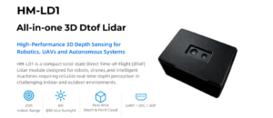
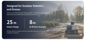
HM-LD1 supports indoor or nighttime ranging up to 25 m and outdoor daytime ranging up to 8 m, depending on conditions. It provides real-time depth images and 3D point cloud data for obstacle avoidance, distance detection, autonomous navigation, smart inspection, and robotic vision development. With UART, UDP, and UVC interfaces, it can be integrated with PCs, Raspberry Pi, flight controllers, and embedded platforms for both prototyping and deployment.
Here’s the practical value for small UAV builders: the module is light enough to mount without redesigning the aircraft, low-power enough to avoid a major electrical burden, and flexible enough to support several development paths. That is exactly the kind of balance small drone projects usually need.
HM-LD1 Mechanical and Ranging Specifications
| Specification | DTOF Solid State LiDAR HM-LD1 |
|---|---|
| Dimension | 43.5 mm × 30 mm × 26.5 mm |
| Ranging Capability | Indoor: 0.5–25 m; Outdoor: 0.2–8 m |
| Ranging Accuracy | ±3 cm |
| Field of View | 60° horizontal × 45° vertical |
| Weight | 28 g |
HM-LD1 Output, Interface, and Electrical Specifications
| Specification | DTOF Solid State LiDAR HM-LD1 |
|---|---|
| Resolution | 40 × 30 |
| Frame Rate | 10 fps |
| Interface | UART / UDP / UVC |
| Operating Temperature | -20 ℃ to 60 ℃ |
| Power Consumption | 1.2 W |
For detailed product documentation, download the DTOF SSL HM-LD1 Product Brochure.
View Product Details & Pricing ➔
Why HM-LD1 Fits Small UAV Development
HM-LD1 is a practical fit for small UAV development because its 28 g weight helps preserve payload margin, while 1.2 W power consumption reduces electrical and thermal integration pressure. Its 60° × 45° field of view supports local scene perception, and its 10 fps output can support real-time embedded sensing when the drone speed and control loop are designed appropriately. The UART, UDP, and UVC interfaces support different workflows, from simple embedded communication to PC-based vision development.
The module also supports development across x86 Windows, x86 Linux, and ARM Linux environments. This matters because many teams prototype on PCs and then deploy to embedded platforms. For drone builders, the ability to test depth data, point cloud output, and interface behavior before final airframe integration can reduce engineering risk.
✅ Practical fit: small UAV obstacle awareness, altitude sensing, short-range inspection support, embedded perception, robotics development, and controlled-environment autonomy testing.
What HM-LD1 Is Not
HM-LD1 should not be described as a complete airborne survey mapping payload. It does not replace a full GNSS/INS/LiDAR mapping system, and it is not intended to produce survey-grade georeferenced maps by itself. Its best position is short-range 3D perception, obstacle avoidance, altitude sensing, embedded vision, distance detection, inspection assistance, and robotics development. This distinction is important because it helps engineers choose the correct class of drone mounted LiDAR for the mission.
Look, that limitation is not a weakness. It is proper system classification. A compact sensing module should be judged by how well it supports real-time perception on small platforms, not by whether it replaces an entire survey workflow.
Drone Mounted LiDAR Selection Checklist
Step 1 — Define the Mission
Start by defining whether the goal is mapping, obstacle avoidance, inspection, altitude sensing, terrain following, landing support, or research. If the system must produce georeferenced survey outputs, you need a complete mapping architecture. If the drone only needs local perception, a compact module may be enough.
⚙️ Ask what decision the drone must make: hold height, avoid an obstacle, maintain standoff, inspect a structure, follow terrain, or build a survey deliverable.
Step 2 — Calculate Payload Budget
Calculate maximum drone payload, current installed payload, remaining weight after battery, camera, computer, mount, cables, and regulators, and the required flight time. Leave margin for safe maneuvering and real-world conditions. Do not evaluate the LiDAR weight alone.
⚙️ Include the hidden hardware: brackets, fasteners, wiring, regulators, enclosures, vibration control, and any onboard processor needed to use the data.
Step 3 — Match Range to Flight Speed
A fast drone needs longer detection distance because it requires more time to slow down, stop, or reroute. A slow indoor inspection drone may be safe with shorter-range sensing. Always evaluate range, frame rate, latency, and stopping distance together.
⚙️ Estimate how far the UAV travels during sensor acquisition, data transfer, software processing, and flight controller response. That distance is part of the safety margin.
Step 4 — Check Outdoor Performance
If the UAV operates outdoors, review sunlight performance carefully. Consider target materials, surface angles, dark objects, reflective surfaces, transparent surfaces, wet materials, and expected lighting conditions. Outdoor range is often shorter than indoor range.
⚙️ Test against the surfaces the drone will actually see, such as concrete, asphalt, vegetation, metal, glass, water, painted structures, or dark industrial equipment.
Step 5 — Verify Interface Compatibility
Confirm whether your flight controller, companion computer, or embedded platform supports UART, UDP, or UVC. Check SDK availability and operating system support. If your team uses Windows, Linux, ARM Linux, ROS, OpenCV, C++, or Python, confirm that the data can be accessed in the required workflow.
⚙️ Before committing to hardware, make sure you can read the data, visualize it, log it, and feed it into your control or perception stack.
Step 6 — Plan Mechanical Integration
Decide whether the LiDAR will face forward, downward, or at an angle. Plan vibration control, cable routing, weather protection, sensor window cleaning, and center-of-gravity effects. Mechanical integration can determine whether the sensor performs reliably in flight.
⚙️ Treat mounting as part of the sensing system. A poorly mounted sensor can make good electronics look bad.
Common Mistakes When Choosing Drone Mounted LiDAR
Mistake 1 — Buying Survey LiDAR for a Perception Problem
If the goal is local obstacle sensing, a full survey payload may be excessive. Survey LiDAR is valuable when the deliverable is a georeferenced map, but it can be too heavy, expensive, and complex for simple distance sensing or embedded perception.
✅ Better approach: match the LiDAR class to the deliverable. Use survey payloads for survey deliverables and compact modules for local perception.
Mistake 2 — Ignoring Total Payload Weight
A 28 g sensor is only part of the payload. Brackets, cables, power regulation, processors, housings, and vibration mounts all add mass. Always calculate total installed weight before selecting the airframe or finalizing the mission plan.
✅ Better approach: build a full installed-weight budget before ordering parts.
Mistake 3 — Comparing Range Without Considering Sunlight
Indoor range and outdoor range can differ significantly. Sunlight, surface reflectivity, and target angle can reduce performance. A LiDAR that performs well indoors may need testing before outdoor deployment in bright conditions.
✅ Better approach: evaluate indoor range, outdoor daytime range, target reflectivity, and mission lighting separately.
Mistake 4 — Overlooking Interface and SDK Support
Good hardware specifications do not guarantee easy integration. If the interface is incompatible with the flight controller or companion computer, development can become slow and expensive. SDK support and documentation should be part of the selection process.
✅ Better approach: confirm platform support before purchase, especially if the final system will run on ARM Linux, Raspberry Pi, Jetson, or a flight-controller companion computer.
Mistake 5 — Assuming LiDAR Alone Solves Navigation
LiDAR provides distance and depth information, but navigation usually requires sensor fusion. IMU, barometer, GNSS, optical flow, camera, RTK, or visual-inertial systems may be needed depending on the mission and environment.
✅ Better approach: design LiDAR as part of a sensing stack, not as a magic replacement for every other sensor on the aircraft.
Mistake 6 — Confusing Local Distance Accuracy with Survey Mapping Accuracy
A compact module may provide accurate local distance measurements but cannot create survey-grade georeferenced maps without localization hardware, synchronization, calibration, and processing. Always match the LiDAR class to the required deliverable.
✅ Better approach: separate local perception requirements from mapping requirements at the beginning of the project.
Sharing a compact dToF sensor we’ve been working with for drone obstacle av…