


High Precision IMU Selection Guide for Robotics, Drones, and Industrial Navigation
A high precision IMU can improve stabilization, state estimation, dead reckoning, and motion control. Here’s the deal: “high precision” is not a measurable performance class by itself. Two modules with the same axis count and output rate can behave very differently once they see vibration, temperature changes, mechanical stress, timing errors, and long operating periods. Engineers should compare bias instability, random walk, scale-factor behavior, cross-axis error, bandwidth, calibration coverage, timing, and environmental performance instead of choosing a sensor from one attractive accuracy number.
This guide explains how to evaluate a high precision IMU for mobile robots, drones, autonomous platforms, industrial machinery, and multi-sensor navigation systems. It connects datasheet parameters to what happens in the field, compares 6-axis and 9-axis architectures, identifies common integration mistakes, and lays out a practical qualification process. It also examines the Industrial High Precision IMU HM-G12 using its published gyroscope, accelerometer, interface, environmental, and mechanical specifications.
Table of Contents
- 👉 What Is a High Precision IMU?
- 👉 How an IMU Measures Motion
- 👉 Specifications That Determine IMU Precision
- 👉 6-Axis vs. 9-Axis IMUs
- 👉 Selecting an IMU by Application
- 👉 Sensor Fusion and Navigation Architecture
- 👉 Mechanical and Electrical Integration
- 👉 Testing and Validating an IMU
- 👉 HM-G12 Specifications
- 👉 High Precision IMU Selection Checklist
- 👉 Frequently Asked Questions
What Is a High Precision IMU?
An inertial measurement unit measures angular velocity and linear acceleration along orthogonal axes. A conventional 6-axis IMU combines a three-axis gyroscope with a three-axis accelerometer. A 9-axis device adds a three-axis magnetometer. That extra sensor can provide a magnetic heading observation in the right environment, but it does not automatically make the IMU more accurate or more useful for navigation.
“High precision” is an application-dependent engineering description, not a universal certification category. An IMU that works well in a stabilized indoor robot may fail to meet the drift, vibration, thermal, shock, latency, or synchronization requirements of a drone or outdoor mapping platform. The practical answer is to define the operating envelope first, then compare multiple quantified parameters.
Precision, Accuracy, Resolution, and Repeatability
- ✅ Precision describes how consistently measurements can be reproduced.
- ✅ Accuracy describes how close a measurement is to the true physical value.
- ✅ Resolution is the smallest output change that can be represented.
- ✅ Repeatability indicates whether the same input produces comparable results across repeated tests.
- ✅ Stability describes how much output changes over time or environmental conditions.
- ✅ Noise is short-term random variation in sensor output.
A high-resolution digital output can still contain substantial bias, drift, scale-factor error, and noise. More output bits do not compensate for inadequate calibration, poor thermal stability, uncertain timing, or unsuitable mechanical installation. In the shop, this is one of the first distinctions worth making: resolution tells you what the electronics can represent, not how faithfully the installed system measures motion.
A raw IMU reports acceleration and angular rate. An attitude and heading reference system, or AHRS, uses sensor fusion to estimate orientation. An inertial navigation system, or INS, estimates position, velocity, and attitude, commonly with GNSS or another external aiding source. Procurement documents should identify whether advertised orientation data is measured directly, estimated by onboard fusion, or calculated by host software. These outputs have different error sources and validation requirements.
Raw IMU, AHRS, and INS Are Not Interchangeable
Look closely at the product label before comparing specifications. A raw IMU gives the host angular-rate and acceleration measurements. An AHRS adds an orientation estimate, while an INS adds navigation states such as position and velocity. Each layer introduces processing, assumptions, filtering, timing behavior, and possible failure modes. A supplier’s orientation figure cannot be evaluated the same way as a raw gyro bias specification.
How an IMU Measures Motion
A MEMS IMU converts microscopic mechanical motion into electrical measurements. Gyroscopes measure angular rate around the X, Y, and Z axes, while accelerometers measure specific force along those axes. An onboard microcontroller may handle sampling, calibration coefficients, temperature compensation, filtering, packet formatting, and diagnostics before transmitting measurements to a host processor.
Gyroscope Measurements
Integrating angular rate over time produces an estimate of orientation change. Any gyroscope bias is integrated as well, so even a small offset causes attitude error to accumulate between external corrections. Low bias instability and low angular random walk are consequently important for short-term attitude propagation. In a real three-dimensional estimator, rotations are normally integrated using quaternions, direction cosine matrices, or equivalent representations rather than simple independent angle calculations.
Accelerometer Measurements
An accelerometer does not directly distinguish gravity from vehicle acceleration. When stationary, or during sufficiently gentle motion, the gravity vector can help establish roll and pitch. During rapid translation, impact, vibration, or coordinated turns, acceleration measurements may not provide a reliable gravity reference. Accelerometer bias is especially important in navigation because an acceleration error affects velocity after one integration and position after two integrations.
Why Calibration Matters
Calibration addresses zero bias, scale factor, nonlinearity, axis alignment, cross-axis sensitivity, and temperature dependence. Full-temperature calibration should mean that the module has been characterized and compensated across its specified range. Buyers should still request the calibration method, residual-error data, axis-level results, soak conditions, ramp rates, and power-cycle repeatability. A calibration statement is useful only when its scope and remaining errors are understood.
Specifications That Determine IMU Precision
No single datasheet value determines navigation accuracy. A defensible comparison considers stochastic noise, time-varying bias, dynamic range, frequency response, temperature behavior, axis alignment, timing, and the test conditions used to generate each figure.
Gyroscope Bias Instability
Gyroscope bias instability describes the tendency of zero-rate output to vary over time. It is commonly characterized using Allan deviation, but the reported result depends on test duration, sampling, filtering, mounting, temperature stability, and the method used to identify the relevant region of the curve. The HM-G12 publishes gyro bias instability of ≤ 1.4°/h. This must not be translated directly into a guaranteed one-hour heading error because actual attitude error also depends on motion, estimator design, calibration, initial alignment, integration intervals, and external corrections.
Gyroscope Bias Stability
Some suppliers publish both bias instability and bias stability. The HM-G12 lists gyro bias stability at ≤ 4°/h in addition to its bias-instability value. These terms should not be treated as interchangeable without a supplier definition. Engineers should request the test method, time interval, temperature conditions, statistical interpretation, and whether values are typical or maximum.
Angular Random Walk
Angular random walk represents angle uncertainty introduced by broadband gyroscope noise during integration. Lower values generally support cleaner short-term attitude propagation. The HM-G12 publishes angular random walk of ≤ 0.15°/√h. This is relevant when external aiding is intermittent, but it does not characterize every source of long-duration drift, vibration sensitivity, or temperature-related error.
Accelerometer Bias Instability
Accelerometer bias affects velocity after one integration and position after two. A small offset can therefore become significant in unaided navigation. The HM-G12 publishes accelerometer bias instability of 0.016 mg. When comparing products, request axis-by-axis results, temperature behavior, repeatability after power cycling, and in-run stability. A single aggregate value may conceal meaningful differences among axes.
Velocity Random Walk
Velocity random walk describes velocity uncertainty associated with accelerometer noise. The HM-G12 publishes 0.018 m/s/√h. This parameter helps compare short-term inertial performance, but practical position drift also depends on acceleration bias, vibration rectification, gravity compensation, mounting alignment, estimator constraints, and the quality of external aiding.
Measurement Range and Saturation
Measurement range must cover normal dynamics plus credible shocks and maneuvering margin. The HM-G12 accelerometer range is ±16 g. If a sensor saturates, the estimator loses motion information and may require time or an external observation to recover. Drone qualification should include takeoff, landing, propeller vibration, aggressive maneuvers, and impact cases. Industrial machinery testing should include startup transients, hard stops, tool impacts, and emergency-stop behavior.
Bandwidth and Output Rate
Bandwidth describes the frequency range that the measurement chain can meaningfully track. Output rate describes how frequently samples are delivered. Internal sampling may occur at another rate and should not be inferred from either value. The HM-G12 publishes 200 Hz gyroscope and accelerometer bandwidth and a 1000 Hz output rate. A 1000 Hz stream does not create 1000 Hz of independent physical bandwidth, although it may reduce update intervals, support lower control-loop latency, and provide finer timing granularity depending on internal filtering and communication behavior.
Cross-Axis Coupling and Orthogonality Error
Imperfect alignment causes motion around or along one axis to appear on another. The HM-G12 specification table identifies gyroscope orthogonality error of ≤ 0.05°, while its product description refers to gyro cross-axis coupling at the same threshold. A buyer should confirm whether these descriptions refer to the same test and mathematical definition. Stable alignment errors can be compensated in host calibration, but stress-dependent or temperature-dependent changes require further characterization.
Temperature Calibration
Bias and scale factor can change as temperature changes. The HM-G12 is specified for operation from -40°C to +85°C and is described as factory calibrated across that range. Qualification should still examine temperature sweep plots, residual bias, scale-factor residuals, soak time, ramp rate, hysteresis, and power-cycle repeatability. Ambient temperature may differ substantially from the sensor die temperature when the module is mounted near motors, processors, power regulators, or enclosed heat sources.
Timing, Latency, and Jitter
Timing quality is essential for control and multi-sensor fusion, even when a datasheet does not publish it. Engineers should request timestamp origin and resolution, end-to-end latency, output jitter, clock drift, synchronization inputs, packet-loss behavior, and confirmation that angular-rate and acceleration samples represent the same instant. A high output rate cannot compensate for uncertain timestamps. Misalignment by only a few milliseconds can create significant residuals during rapid motion.
6-Axis vs. 9-Axis IMUs
| Decision factor | 6-axis IMU | 9-axis IMU |
|---|---|---|
| Sensors | 3-axis gyro and accelerometer | Gyro, accelerometer, and magnetometer |
| Roll and pitch reference | Gravity under suitable motion conditions | Gravity under suitable motion conditions |
| Heading reference | Requires another source or motion constraints | Magnetometer may provide heading |
| Magnetic sensitivity | No direct magnetometer dependency | Can be affected by motors, steel, wiring, and current |
| Typical fusion partners | GNSS, RTK, vision, LiDAR, wheel odometry | The same sources plus magnetic heading |
| Best fit | Magnetically difficult environments and externally aided navigation | Environments with a validated magnetic field |
Adding a magnetometer increases the number of measured axes, not necessarily navigation quality. Magnetic heading can be unreliable near motors, high-current conductors, batteries, steel frames, magnetic fasteners, tools, and changing payloads. A calibrated 6-axis unit may be appropriate when stronger heading references are available through RTK GNSS, vision, LiDAR, wheel constraints, or another navigation subsystem. It is not universally superior, and it cannot independently maintain bounded absolute yaw indefinitely.
Developers designing visual-inertial estimation can review the practical failure modes described in 3 Core Challenges in VIO Systems.
Selecting an IMU by Application
Mobile Robots and Autonomous Ground Vehicles
Ground robots encounter wheel slip, floor transitions, ramps, impacts, low-speed observability problems, and indoor GNSS denial. An IMU can propagate attitude and motion between visual, LiDAR, encoder, or GNSS updates, but its benefit depends on timestamp quality and a correctly measured transform to the vehicle frame. Non-holonomic constraints and stationary updates may reduce drift when their assumptions remain valid. For a wider treatment of this workflow, read Precise Robot Localization Made Easy.
Multirotor and Fixed-Wing Drones
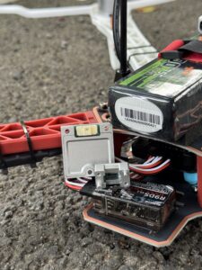
Drone selection should prioritize control-loop latency, vibration behavior, saturation margin, reliable high-rate delivery, and estimator recovery after aggressive maneuvers. Propeller and motor harmonics can alias into the measurement band or create vibration-induced bias. Bandwidth, internal filtering, mounting, and controller design must therefore be coordinated. Thermal behavior also matters because altitude, airflow, sunlight, and internal electronics can create rapid temperature changes.
Industrial Machinery and Platform Stabilization
Industrial systems may run continuously under vibration, thermal gradients, electrical noise, and repeated startup cycles. Stable mechanical alignment can matter as much as nominal sensor noise. Qualification should address mounting torque, connector retention, cable routing, ground quality, warm-up behavior, maintenance practices, and whether replacing a module preserves the original alignment.
Outdoor Navigation and Mapping
IMUs support GNSS outage bridging, LiDAR motion compensation, scan alignment, and trajectory estimation. General background is available from Wikipedia’s LiDAR overview, while manufacturers such as Hesai Technology illustrate the wider LiDAR hardware ecosystem used in autonomous systems. These resources provide context and are not evidence of HM-G12 performance. Engineers evaluating ranging hardware can also review the MRP-HM-LD1 dToF LiDAR Distance Test Report.
Robotic Arms and Precision Motion Systems
Robotic arms impose rapid direction changes, tool vibration, changing payload inertia, and strict reference-frame requirements. An IMU can support dynamic compensation, impact detection, vibration monitoring, or end-effector state estimation. It normally does not replace joint encoders, external metrology, or calibrated machine kinematics because inertial integration alone does not provide permanently bounded absolute position.
Sensor Fusion and Navigation Architecture
An IMU provides high-rate relative motion information but accumulates error. External sensors provide lower-rate or environment-dependent corrections. Robust navigation combines these complementary characteristics instead of expecting one sensor to solve every observability problem.
Common Fusion Inputs
- ✅ GNSS and RTK provide outdoor global position and, in some configurations, heading.
- ✅ Cameras support visual odometry and visual SLAM when scenes contain sufficient usable features.
- ✅ LiDAR supports scan matching, mapping, and geometric constraints.
- ✅ Wheel encoders measure constrained ground motion but can be affected by slip.
- ✅ Barometers provide pressure-based altitude-change observations.
- ✅ Magnetometers may constrain heading after the magnetic environment is validated.
Filter and Estimator Choices
Complementary filters can provide efficient attitude estimation for constrained applications. Extended Kalman filters and error-state Kalman filters support probabilistic state propagation and correction. Factor graphs can optimize trajectories using measurements distributed across time. Tightly coupled estimators retain more information from raw sensor observations but require greater implementation discipline. The correct choice depends on dynamics, available references, processing resources, fault handling, and required recovery behavior.
Coordinate Frames and Conventions
Integration documentation must define axis orientation, handedness, units, sign direction, packet ordering, and the transform from the IMU frame to the vehicle or body frame. A small mounting-angle error can generate systematic cross-axis effects. Frame definitions should be measured and version-controlled rather than inferred from the enclosure shape.
When the IMU Becomes the Limiting Factor
Before replacing hardware, inspect raw stationary data, vibration spectra, estimator innovations, residuals, clipping events, temperature correlation, packet continuity, and timestamp alignment. Poor tuning, an incorrect transform, delayed measurements, or structural resonance can resemble inadequate sensor precision. Controlled tests help separate the sensor’s limitations from integration and estimator defects.
Mechanical and Electrical Integration
Mounting Location and Rigidity
Mount the IMU on a rigid structure with a known transform to the vehicle frame. Avoid flexible panels and locations exposed to severe vibration, changing heat sources, or unnecessary cable motion. Soft isolation can attenuate high-frequency vibration, but it can also introduce resonance and relative motion. Isolation should be designed from measured spectra and validated through the full operating envelope.
Power and Logic Levels
The HM-G12 requires DC 5 ± 0.5 V input, specifies operating current of ≤ 31 mA, uses a 10-pin connector, and identifies a 3.3 V digital signal level. Its default external data interface is UART × 1. A 5 V supply requirement does not mean that the digital pins are 5 V tolerant. Designers should confirm the pinout, grounding, level compatibility, supply ripple, startup sequence, cable length, connector retention, and electromagnetic compatibility before connecting the module.
UART Throughput and Packet Handling
Serial bandwidth must be calculated from packet size, baud rate, update frequency, framing overhead, and diagnostic traffic. At 1000 Hz, the host must receive and parse packets without blocking control or estimator tasks. The design should detect malformed packets, checksum failures, missing sequence numbers, overruns, and stale data. Adequate throughput margin is necessary because nominal payload size is not the complete transmission cost.
Software Integration
Driver work should cover packet validation, checksum handling, sequence counters, unit conversion, coordinate transforms, dropped-sample detection, buffering, monotonic timestamps, configuration persistence, and health status. ROS integration also requires verified frame IDs, units, covariance semantics, and timestamp origin. Publishing a message is not sufficient if the host time does not correspond to the physical sampling instant.
How to Test and Validate a High Precision IMU
1. Datasheet and Documentation Review
⚙️ Request the conditions attached to every headline metric. Separate typical values from guaranteed limits and identify unspecified characteristics. Confirm whether performance applies to all axes, the full temperature range, and the intended output configuration.
2. Stationary Noise Test
⚙️ Log raw measurements on a rigid, stationary base after thermal stabilization. Calculate mean, standard deviation, power spectral density, and axis correlation. Repeat the test across several power cycles and, where practical, in different physical orientations to expose gravity-related and axis-specific behavior.
3. Allan Deviation Analysis
⚙️ Use sufficiently long stationary recordings to estimate white noise, bias instability, and other stochastic behavior. Sampling rate, digital filtering, test duration, vibration, and environmental conditions must be held consistent when products are compared. Retain raw data so analysis settings can be reviewed later.
4. Temperature Test
⚙️ Evaluate cold starts, hot starts, temperature ramps, stabilized soaks, and repeated cycles. Compare compensated output against both temperature and elapsed time. A controlled environmental chamber is preferable for formal qualification. Testing in the final enclosure remains necessary because internal thermal gradients may differ from chamber air temperature.
5. Vibration and Shock Test
⚙️ Use measured platform vibration profiles when possible. Evaluate saturation, clipping, aliasing, vibration-induced bias, connector reliability, structural resonance, and recovery after shock. Inspect the output both in the time domain and frequency domain rather than relying only on aggregate RMS noise.
6. Timing Test
⚙️ Measure sample spacing, transmission latency, output jitter, packet loss, and host timestamp error. In multi-sensor systems, verify synchronization against camera, LiDAR, GNSS, encoder, or controller clocks. Repeat the test under realistic host CPU and interface load.
7. Integrated Motion Test
⚙️ Run representative trajectories and compare results against a trusted reference. Depending on the application, that reference may be a rate table, motion-capture system, surveyed path, high-grade navigation system, calibrated fixture, or precision encoder. Include normal operation, maximum dynamics, expected outages, and recovery scenarios.
8. Acceptance Criteria
⚙️ Define pass and fail thresholds before testing. Criteria may include warm-up time, drift, noise, thermal residuals, packet reliability, latency, mechanical fit, estimator innovation statistics, and final trajectory error. Production acceptance should also define sampling strategy and traceability.
Industrial High Precision IMU HM-G12 Specifications
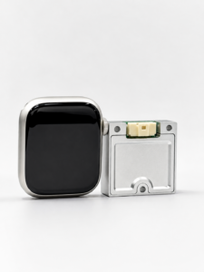
The Industrial High Precision IMU HM-G12 is a compact 6-axis module combining three-axis gyroscopes, three-axis accelerometers, and an MCU. It is presented for drones, robotics, industrial motion sensing, and externally aided navigation. Its product description highlights full-temperature calibration, high-rate output, a compact package, UART communication, and screw mounting. The specifications below reproduce the supplied published values without inventing missing performance data.

Gyroscope Specifications
| Parameter | Published specification |
|---|---|
| Bandwidth | 200 Hz |
| Angular random walk | ≤ 0.15°/√h |
| Bias instability | ≤ 1.4°/h |
| Bias stability | ≤ 4°/h |
| Orthogonality error | ≤ 0.05° |
Accelerometer Specifications
| Parameter | Published specification |
|---|---|
| Accelerometer range | ±16 g |
| Velocity random walk | 0.018 m/s/√h |
| Bias instability | 0.016 mg |
| Bias stability | 0.055 mg |
| Bandwidth | 200 Hz |
Electrical Interface
| Parameter | Published specification |
|---|---|
| External data interface | UART × 1 (default) |
| Operating current | ≤ 31 mA |
| Input voltage | DC 5 ± 0.5 V |
| Interface type | 10-pin connector, 3.3 V digital signal level |
Mechanical and Environmental Specifications
| Parameter | Published specification |
|---|---|
| Dimensions | 30 mm × 30 mm × 10.6 mm |
| Operating temperature | -40°C to +85°C |
| Weight | 14 g |
| Storage temperature | -40°C to +85°C |
| Published output rate | 1000 Hz |
Interpreting the HM-G12 as a System Component
The 200 Hz sensor bandwidth and 1000 Hz output rate serve different purposes. The output rate may support responsive host processing and finer update intervals, while bandwidth defines the published motion-frequency range. The 30 × 30 × 10.6 mm package, 14 g mass, 10-pin connector, UART interface, and screw-mounting format are practical integration factors. Final selection should also account for timing behavior, communication protocol, axis conventions, calibration residuals, mounting design, and performance under the intended vibration and temperature profile.
The supplied product description mentions functional safety and a built-in redundant architecture. Those claims should be assessed only after supporting documents define the architecture, diagnostics, failure coverage, and any applicable safety standard. They should not be inferred from the numerical specification tables alone.
High Precision IMU Selection Checklist
- ⚙️ Define maximum angular-rate and acceleration ranges.
- ⚙️ Identify required control-loop and estimator update rates.
- ⚙️ Compare sensor bandwidth separately from output rate.
- ⚙️ Review gyro bias instability and its test methodology.
- ⚙️ Review angular random walk.
- ⚙️ Review accelerometer bias instability and velocity random walk.
- ⚙️ Confirm scale-factor, nonlinearity, and axis-alignment specifications.
- ⚙️ Confirm vibration, shock, clipping, and saturation requirements.
- ⚙️ Verify calibrated, operating, and storage temperature ranges.
- ⚙️ Request warm-up and power-cycle repeatability data.
- ⚙️ Confirm timestamp source, latency, jitter, and synchronization options.
- ⚙️ Verify electrical supply and digital logic levels independently.
- ⚙️ Calculate interface throughput at the required output rate.
- ⚙️ Check dimensions, mass, connector retention, and mounting method.
- ⚙️ Confirm coordinate conventions, units, signs, and packet definitions.
- ⚙️ Determine whether heading comes from magnetometers, GNSS, vision, LiDAR, or another source.
- ⚙️ Test with the final mechanical mount, enclosure, and representative cabling.
- ⚙️ Validate performance using application-specific trajectories.
- ⚙️ Define acceptance thresholds before purchasing production quantities.
- ⚙️ Evaluate documentation, engineering support, lifecycle, and supply continuity.
A high precision IMU should be selected as part of a complete sensing, computing, timing, and mechanical system. The lowest isolated noise value does not guarantee the best deployed result. The sensor, wiring, mount, firmware, estimator, and external references all contribute to what the machine ultimately does.
[IMAGE_PLACEHOLDER_2]
Frequently Asked Questions
How do I choose a genuinely high-accuracy IMU instead of relying on marketing claims?
Can a high precision IMU achieve absolute tilt accuracy near ±1 mrad?
Should I choose a 6-axis or 9-axis IMU for a robot, drone, or outdoor odometry system?
Is a 1000 Hz IMU output rate always better than 200 Hz?
How long can an IMU navigate without GNSS, vision, or LiDAR updates?
Does full-temperature calibration eliminate IMU drift?
Can a high precision IMU replace GNSS, encoders, or machine vision?
What integration information should I request before ordering an IMU?
📚 References & Further Reading
-
- Product Reference: Industrial High Precision IMU HM-G12






