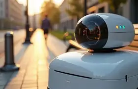
What Is a LiDAR Sensor? How It Works, Benefits, and Selection Guide for Robotics
A robot cannot navigate safely by knowing only that an object exists. It has to estimate how far away that object is, where it sits in three-dimensional space, and whether the measurement stays dependable when lighting, surface reflectivity, or motion changes. Cameras provide excellent visual information, but a conventional camera does not directly measure depth. A LiDAR sensor addresses that gap by emitting laser light and analyzing the reflected signal to calculate distance.
For robotics and UAV developers, the practical question is not simply, “What is a LiDAR sensor?” The better question is which LiDAR architecture fits the job. A compact direct Time-of-Flight, or dToF, module may be the right choice for obstacle avoidance, navigation, altitude hold, and depth sensing. A rotating scanner or long-range industrial LiDAR may make more sense for mapping a large outdoor environment. This guide covers the operating principle, sensor types, output data, specifications, integration requirements, limitations, and product-selection criteria for robotics applications, including the HM-LD1-NV and HM-LD1 solid-state dToF modules.
Here’s the deal: LiDAR is not a magic “object detector.” It is a geometry sensor. It measures the relationship between the sensor and reflecting surfaces, then leaves the robot’s software to decide whether that geometry represents a wall, person, tree, vehicle, machine, or obstacle.
In the shop, that distinction matters. A sensor can have excellent accuracy on a test target and still perform poorly after it is mounted behind a protective window, exposed to sunlight, subjected to vibration, or connected to a host with excessive processing latency.
Sharing a compact dToF sensor we’ve been working with for drone obstacle av…
Table of Contents
- 👉 What Is a LiDAR Sensor?
- 👉 How Does LiDAR Work?
- 👉 What Is dToF LiDAR?
- 👉 Types of LiDAR Sensors
- 👉 What Data Does a LiDAR Sensor Produce?
- 👉 LiDAR vs. Cameras and Other Sensors
- 👉 LiDAR Applications in Robotics
- 👉 Key LiDAR Specifications
- 👉 LiDAR Sensor Product Comparison
- 👉 How to Choose a LiDAR Sensor
- 👉 LiDAR Integration Guide
- 👉 LiDAR Limitations and Design Considerations
- 👉 Frequently Asked Questions
What Is a LiDAR Sensor?
LiDAR is a sensing technology that uses laser light to measure distance and collect information about surrounding objects and surfaces. The name is commonly associated with Light Detection and Ranging. A LiDAR sensor emits optical energy, receives part of that energy after it reflects from a target, measures the return, and converts the result into distance or spatial data.
Unlike a conventional laser pointer, a LiDAR sensor is a complete measurement system. It combines a laser emitter, optical elements, a photodetector, timing or phase-measurement electronics, signal-processing algorithms, a housing, and one or more communication interfaces. Depending on the architecture, it may return one distance value, scan a two-dimensional plane, generate a depth map, or produce a three-dimensional point cloud.
The basic direct Time-of-Flight relationship is:
Distance = (speed of light × measured round-trip time) ÷ 2
The result is divided by two because the light travels from the sensor to the target and then back to the receiver. A nearby object produces a shorter round-trip time. A more distant object produces a longer one.
LiDAR does not automatically understand whether a return represents a person, wall, tree, vehicle, or piece of equipment. It measures geometry. Robotics software can interpret that geometry for obstacle detection, navigation, mapping, SLAM, terrain following, human-presence detection, gesture recognition, and autonomous motion planning.
For embedded robotic perception, the HM-LD1-NV 3D dToF LiDAR sensor is designed to provide real-time depth and point-cloud information in a compact module for robots, drones, and autonomous machines.
How Does LiDAR Work?
A LiDAR measurement starts when the transmitter sends laser light toward a scene. The receiver looks for the reflected signal, and the processing electronics calculate the target distance. In a multi-pixel device, this happens across multiple sensing positions, allowing the system to build a spatial representation instead of returning only one range value.
Laser emission
The transmitter may emit short laser pulses or modulated optical energy. The HM-LD1-NV uses a 940 nm VCSEL. VCSEL means vertical-cavity surface-emitting laser. VCSEL devices are widely used in compact infrared sensing systems because they can provide controlled optical emission in a small package.
Infrared light is normally invisible to the human eye, but that does not remove the need for safety engineering. The HM-LD1-NV is described as using Class 1 eye-safe illumination. Engineers should verify compliance for the complete integrated product, particularly if the optical path, enclosure, firmware, or operating conditions are changed.
Reflection from a target
When the emitted light reaches an object, part of the optical energy reflects toward the sensor. The strength and quality of that return depend on target distance, color, reflectivity, material, surface angle, texture, and ambient illumination.
A white or highly reflective surface generally returns more optical energy than a dark, absorbent surface. A target angled away from the receiver may return less usable light. Glass, water, polished surfaces, and complex backgrounds can create reflections or multiple return paths that require careful interpretation.
Photon detection
The receiver collects returned light and converts it into an electrical signal. The HM-LD1-NV product information identifies a high-sensitivity SPAD sensor. SPAD means single-photon avalanche diode. SPAD-based receivers are designed to detect very weak optical signals, including individual returned photons under suitable conditions.
High detector sensitivity can help a module measure low-reflectivity targets or operate in challenging environments. It does not eliminate every measurement error. Target properties, sunlight, optical alignment, signal processing, calibration, and the selected operating mode still affect the final result.
Time measurement and distance calculation
In a direct Time-of-Flight system, the electronics measure the interval between the outgoing optical event and the detected return. The processor uses this timing information to calculate distance. The result may then be filtered, calibrated, assigned to a pixel, and transmitted through an interface such as UART, UDP, or UVC.
Depth-map and point-cloud generation
A multi-pixel LiDAR module measures multiple directions within its field of view. The HM-LD1-NV provides 40 × 30 resolution, representing 1,200 nominal spatial samples before invalid-data handling, filtering, or other processing. These measurements can be used to generate depth data and point-cloud information.
A depth map is a two-dimensional array in which each sensing position contains a distance value. A point cloud is a collection of three-dimensional points representing measured surfaces or objects. Point clouds are useful for obstacle segmentation, collision checking, mapping, and spatial analysis.

What Is dToF LiDAR?
dToF stands for direct Time-of-Flight. It is a ranging method that measures the actual travel time of emitted photons as they move to a target and return to the sensor. This approach is relevant to systems that need direct range information for obstacle avoidance, depth perception, UAV altitude measurement, terrain following, and robot navigation.
dToF versus iToF
Both direct and indirect Time-of-Flight technologies measure depth using optical signals, but the measurement methods differ.
| Attribute | dToF | iToF |
|---|---|---|
| Measurement principle | Measures photon travel time directly | Measures the phase shift of modulated light |
| Typical output | Direct range or depth information | Depth calculated from phase information |
| Important considerations | Photon timing, detector sensitivity, ambient light, and return strength | Modulation frequency, phase ambiguity, and multipath effects |
| Common applications | Robotics, ranging, obstacle detection, and depth sensing | Consumer depth cameras, industrial sensing, and embedded 3D systems |
Neither architecture is automatically the best choice for every application. Engineers should compare operating range, accuracy, scene conditions, output requirements, processing load, ambient-light performance, power consumption, and total system cost.
Why SPAD receivers matter
A SPAD receiver can detect weak optical returns, which is useful when the target reflects only a small amount of the emitted light. That characteristic can support measurements on darker or less reflective surfaces, although final range still depends on the complete optical and electronic design. The HM-LD1-NV combines dToF operation with a high-sensitivity SPAD sensor for real-time three-dimensional perception.
Types of LiDAR Sensors
Single-point LiDAR sensors
A single-point LiDAR sensor measures distance to one primary target or a narrow sensing region. This type of device is suitable for proximity detection, level measurement, altitude hold, simple distance control, and object-presence detection. It generally does not provide a complete scene representation, so additional sensors may be needed when a robot must identify obstacles across a broad area.
Two-dimensional scanning LiDAR
A 2D scanning LiDAR sweeps across one plane to create a range profile. Mobile robots commonly use this information for wall following, corridor detection, indoor mapping, and two-dimensional SLAM. Its usefulness depends heavily on the scan plane. A sensor mounted too high or too low may miss important obstacles, overhanging objects, or changes in terrain.
Three-dimensional LiDAR
A 3D LiDAR captures depth across horizontal and vertical dimensions. It can generate a depth map or point cloud, allowing a robot or UAV to analyze the spatial structure of obstacles and surfaces. Typical applications include three-dimensional obstacle avoidance, object detection, uneven-terrain perception, gesture recognition, spatial mapping, and autonomous inspection.
The HM-LD1-NV and HM-LD1 are compact solid-state 3D dToF modules rather than mechanical rotating scanners. Their compact format suits embedded platforms where space, mass, and power are limited.
Mechanical and solid-state LiDAR
Mechanical LiDAR uses moving optical components to scan a scene. It can provide broad coverage, but moving parts may increase mechanical complexity, package size, and integration requirements. Solid-state LiDAR does not use a rotating scanning assembly in the sensing module and can be easier to package into small robots, drones, cameras, and intelligent machines.
Solid-state does not automatically mean longer range, higher resolution, or better performance in every environment. Actual capability depends on optical design, detector architecture, processing algorithms, field of view, illumination power, and intended operating conditions.
Short-range, medium-range, and long-range LiDAR
LiDAR systems are also categorized by intended measurement distance. Short-range devices are often used for presence detection and close obstacle avoidance. Medium-range modules may support mobile robots, drones, and autonomous machines. Long-range systems are better suited to larger outdoor scenes and extended detection distances.
Manufacturers may define range using different target reflectivity, lighting, and measurement-quality criteria. When comparing sensors, review the test conditions instead of comparing maximum-range numbers alone.
What Data Does a LiDAR Sensor Produce?
Distance values
The simplest LiDAR output is a single distance value. A control system can use this value to trigger a proximity warning, maintain UAV altitude, measure a gap, or stop a mobile platform before it reaches an obstacle.
Depth maps
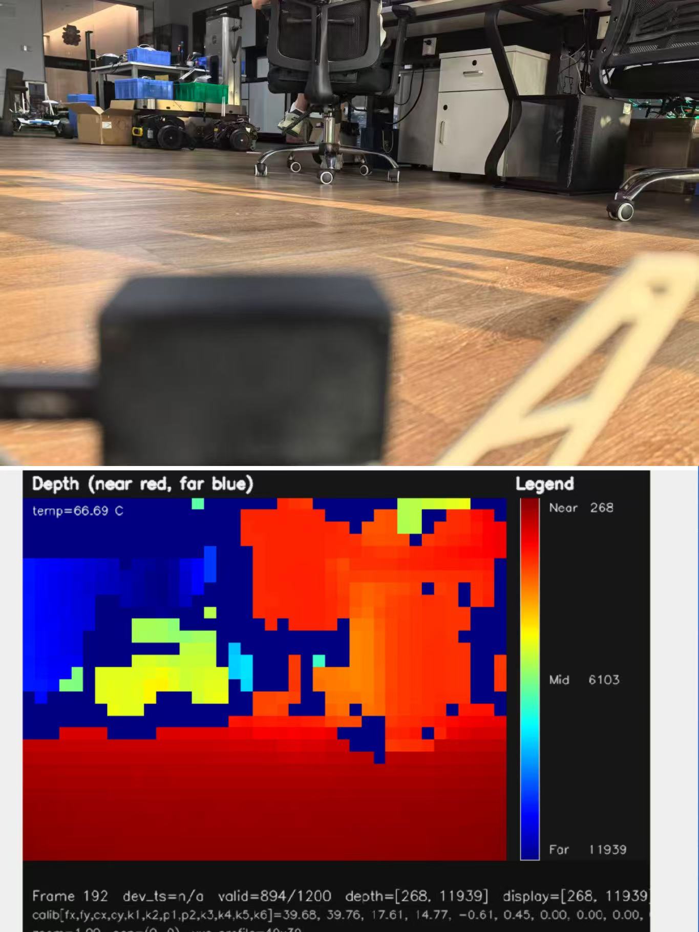
A depth map assigns a distance value to each sensing position or pixel. With a 40 × 30 output, a module can provide a structured grid of range measurements across its field of view. That is more informative than a single range value because software can compare nearby regions and estimate the relative shape of an obstacle.
Point clouds
A point cloud contains spatial coordinates generated from range measurements and sensor geometry. A robot may transform the point cloud into its own coordinate frame, remove invalid points, filter noise, and use the result for obstacle segmentation or mapping.
Processed detections
Some systems provide raw measurements, while others transmit filtered depth, confidence information, detected obstacles, or higher-level objects. The product data for HM-LD1-NV and HM-LD1 identifies depth maps and point-cloud data as important outputs. Before selecting a sensor, verify the SDK documentation, output format, timestamps, calibration information, and data-rate requirements.
LiDAR vs. Cameras and Other Sensors
LiDAR versus RGB cameras
| Capability | LiDAR | RGB camera |
|---|---|---|
| Direct depth measurement | Yes, based on optical ranging | Usually estimated using stereo, motion, structured light, or artificial intelligence |
| Color and texture | Limited compared with an RGB camera | Strong visual and color information |
| Low-light behavior | Depends on active illumination and sensor design | Often becomes weaker without sufficient visible light |
| Privacy characteristics | Can operate without collecting conventional RGB imagery | Captures visual imagery that may identify people or surroundings |
| Geometric information | Direct range and surface geometry | Rich appearance information, with depth often requiring additional processing |
LiDAR and cameras are usually complementary rather than competing technologies. A camera can classify objects using color, texture, and learned visual features. LiDAR provides direct spatial measurements for collision checking and distance estimation.
LiDAR versus ultrasonic sensors
Ultrasonic sensors are inexpensive and useful for nearby detection, but their acoustic beam pattern, response time, spatial resolution, and environmental sensitivity differ from optical LiDAR. LiDAR generally provides more detailed spatial information, while ultrasonic sensing can be useful where optical conditions are difficult or where low-cost close-range detection is the main requirement.
LiDAR versus radar
Radar can offer advantages in certain long-range or adverse-weather conditions and can provide useful information about moving objects. LiDAR is often selected when detailed geometric perception is required at short or moderate distances. The right choice depends on range, spatial resolution, weather, object types, processing requirements, and cost.
LiDAR versus a single-point laser distance sensor
A single-point laser distance sensor measures a narrow target region and returns one principal distance. A 3D LiDAR module samples multiple spatial positions and can generate a depth map or point cloud. Single-point devices are therefore suitable for altitude, level, proximity, or presence measurement, while 3D modules are better suited to obstacle avoidance, navigation, spatial mapping, and three-dimensional perception.
For UAV design considerations, read this related guide on how to choose LiDAR for drones.
LiDAR Applications in Robotics and Autonomous Systems
Robot obstacle avoidance
Depth data can be converted into safety zones around a mobile robot. If measured points enter a defined zone, the navigation system can slow down, change direction, or stop. Engineers must account for vehicle speed, stopping distance, software latency, sensor mounting height, blind areas, and obstacles that are too narrow or too low for the selected field of view.
Autonomous navigation and SLAM
LiDAR can support localization and mapping by identifying stable geometric features such as walls, structural edges, and large objects. A compact 3D module may supplement other sensors, although suitability for SLAM depends on output density, field of view, frame rate, measurement stability, timestamp quality, and the algorithm being used.
Drone obstacle avoidance
UAV applications place strict demands on sensing hardware. The module must be light enough for the airframe, consume limited power, tolerate vibration, fit into a small installation space, and provide sufficiently timely measurements. Bright outdoor conditions are also important because sunlight adds infrared background energy to the receiver.
The HM-LD1-NV is specified at 28 g, with 1.2 W power consumption and a 10 fps frame rate. Its listed outdoor ranging capability is 0.2–8 m at 80 klux sunlight. These characteristics make it relevant to UAV obstacle detection and collision-avoidance designs, subject to application testing.
Altitude hold and terrain following
A downward-facing LiDAR can estimate the distance between a UAV and the ground. The flight controller can use this information to maintain altitude or follow terrain. Test the system on sloped ground, vegetation, gravel, water, and low-reflectivity surfaces because returned signal strength can vary substantially.
Privacy-preserving human sensing
Depth-only sensing can support presence detection, movement tracking, and human-activity recognition without collecting conventional RGB images. This can be useful in smart interfaces, occupancy monitoring, and human-machine interaction. However, depth sensing should not be described as complete privacy protection. Data storage, transmission, access control, and application software must also be designed responsibly.
Gesture recognition and human-machine interfaces
Three-dimensional depth information can identify hand position, finger movement, and gesture trajectories. Performance depends on depth resolution, frame rate, field of view, operating distance, background conditions, and recognition algorithms. A 40 × 30 sensor can provide structured spatial information for development, but the final gesture vocabulary and reliability must be validated in the intended environment.
Inspection and security applications
LiDAR modules can assist with object-presence detection, zone-intrusion monitoring, dimensional checks, autofocus, volume measurement, and smart inspection. These applications generally require software to interpret measured geometry. The sensor supplies depth information; the application determines how that information is classified or acted upon.
Key LiDAR Specifications Explained
Ranging capability
Range should always be stated with operating conditions. The HM-LD1-NV is specified for 0.5–25 m indoors and 0.2–8 m outdoors at 80 klux. The HM-LD1 product page states an indoor capability of 0.5–25 m and an outdoor capability of 0.2–8 m. Actual results can vary with target reflectivity, angle, weather, background, and installation.
Ranging accuracy
Both listed products specify ±3 cm ranging accuracy. Do not confuse accuracy with resolution or repeatability. Accuracy describes closeness to the actual distance. Resolution describes the smallest distinguishable change or the spatial sampling density. Repeatability describes how consistently the sensor produces the same result under repeated conditions.
Field of view
Both products list a field of view of 60° horizontal × 45° vertical. A wide field of view lets a robot see more of the surrounding scene. However, if pixel count remains constant, each target may occupy fewer sensing positions than it would with a narrower field of view. The right balance depends on vehicle geometry and the required obstacle size.
Resolution
The modules provide 40 × 30 resolution. This affects spatial detail, target separation, depth-map structure, and point-cloud density. Resolution is not the same as ranging accuracy. A sensor may measure a target’s distance accurately while still producing relatively coarse spatial detail.
Frame rate and response time
The stated frame rate is 10 fps, equivalent to a nominal update interval of approximately 100 milliseconds before additional system delays are included. Effective response also includes measurement time, interface transmission, host processing, filtering, navigation scheduling, and actuator response. Compare the complete control-loop latency with the platform’s speed and stopping distance.
Ambient-light performance
Sunlight is challenging for infrared receivers because it adds optical background energy and reduces the contrast between emitted light and the returned signal. The HM-LD1-NV’s stated capability of up to 8 m at 80 klux makes it relevant to outdoor robots and UAVs, but test representative targets in the actual installation environment.
Wavelength and eye safety
The HM-LD1-NV uses a 940 nm VCSEL and is described as meeting Class 1 eye-safety requirements. The HM-LD1 supplied product data does not separately specify a wavelength. For production systems, confirm the current brochure and compliance documentation for the exact model and final enclosure.
Interface and software support
The listed interfaces are UART, UDP, and UVC. UART can support embedded serial communication. UDP can support networked real-time data transfer. UVC can support USB video-class host integration, subject to the module’s implementation and driver requirements.
The supplied product information also identifies SDK support for Windows, Linux, and Linux ARM platforms. Confirm sample code, output formats, calibration files, timestamps, drivers, and ROS or ROS2 support before committing to a production architecture.
Weight, size, temperature, and power
Weight, dimensions, operating temperature, and power consumption directly affect drone and mobile-robot deployment. Both product records list housing dimensions of approximately 43.5 mm × 30 mm × 26.5 mm, although the order is presented differently on the two pages. Both list an operating temperature of −20 °C to 60 °C and power consumption of 1.2 W.
The supplied records list different product weights: 28 g for HM-LD1-NV and 8 g for HM-LD1. Preserve that distinction and confirm it against the latest product brochure before production procurement.
LiDAR Sensor Product Comparison
The HM-LD1-NV and HM-LD1 are compact solid-state dToF LiDAR modules intended for robotics, UAVs, embedded platforms, and autonomous systems. Both provide structured depth information through a 40 × 30 sensing output, a 60° horizontal by 45° vertical field of view, 10 fps operation, and UART, UDP, and UVC interfaces.
The HM-LD1-NV is positioned as a compact 3D dToF module for robot and drone perception, obstacle avoidance, and challenging indoor and outdoor environments. Its product information highlights a 940 nm VCSEL, high-sensitivity SPAD detection, real-time depth and point-cloud output, Class 1 eye safety, Raspberry Pi and NVIDIA Jetson compatibility, SDK support, and ROS-friendly development.
The HM-LD1 is described as a solid-state SPAD dToF LiDAR module for obstacle avoidance, navigation, UAV altitude hold, terrain following, SLAM, smart inspection, autofocus, presence detection, object recognition, volume measurement, and zone-intrusion monitoring. It is also described as suitable for PCs, Raspberry Pi, flight controllers, and embedded platforms.
| Specification | HM-LD1-NV | HM-LD1 |
|---|---|---|
| Technology | Compact 3D direct Time-of-Flight LiDAR | Solid-state SPAD dToF LiDAR |
| Resolution | 40 × 30 | 40 × 30 |
| Indoor ranging capability | 0.5–25 m | 0.5–25 m |
| Outdoor ranging capability | 0.2–8 m at 80 klux | 0.2–8 m |
| Ranging accuracy | ±3 cm | ±3 cm |
| Field of view | 60° H × 45° V | 60° H × 45° V |
| Wavelength | 940 nm VCSEL | Not specified in supplied product data |
| Frame rate | 10 fps | 10 fps |
| Interface | UART / UDP / UVC | UART / UDP / UVC |
| Operating temperature | −20 °C to 60 °C | −20 °C to 60 °C |
| Power consumption | 1.2 W | 1.2 W |
| Weight | 28 g | 8 g |
| Typical applications | Robot and drone perception, obstacle avoidance, and depth sensing | Navigation, obstacle avoidance, UAV altitude hold, SLAM, and inspection |
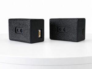
HM-LD1 solid-state dToF LiDAR
The HM-LD1 is a compact solid-state LiDAR module based on SPAD dToF technology. Its supplied specifications include 40 × 30 resolution, 0.5–25 m indoor ranging, 0.2–8 m outdoor ranging, ±3 cm accuracy, 60° × 45° field of view, 10 fps output, UART/UDP/UVC interfaces, −20 °C to 60 °C operating temperature, and 1.2 W power consumption. The listed product weight is 8 g.
The module is presented for robots, drones, cameras, security systems, flight controllers, Raspberry Pi platforms, PCs, and embedded Linux systems. Its application descriptions include UAV altitude hold and terrain following, robot navigation, obstacle avoidance, SLAM, autofocus, presence detection, object recognition, volume measurement, and zone-intrusion monitoring.
View Product Details & Pricing ➔
Download the technical documentation before integration: HM-LD1-NV product brochure and HM-LD1 product brochure.
How to Choose a LiDAR Sensor for Robotics
1. Define the required sensing range
Separate indoor, nighttime, and outdoor-daylight requirements. A sensor that reaches 25 m indoors may not deliver the same range under direct sunlight. If the robot operates outside, evaluate target distance and illumination together instead of choosing a module only by its maximum indoor range.
2. Specify the required data type
Determine whether the application needs a single distance value, a 2D scan, a depth map, a 3D point cloud, or processed obstacle detections. Choosing a 3D module for a simple altitude measurement may add unnecessary processing. Using a single-point sensor for wide-area obstacle avoidance may leave unacceptable blind zones.
3. Match field of view to platform geometry
A forward-facing drone may require broad horizontal coverage, while a downward-facing altitude sensor may prioritize ground visibility. Consider mounting angle, sensor height, protective housing, vehicle bodywork, landing gear, and any other structure that could obstruct the optical field.
4. Calculate motion and response requirements
Compare frame rate with platform speed, stopping distance, processing delay, and control-loop requirements. A 10 fps device has a nominal update interval of approximately 100 milliseconds before interface, computation, filtering, and actuator delays. A fast-moving platform may need additional sensing or a different architecture.
5. Check target reflectivity and lighting
Test black, gray, white, glossy, transparent, angled, and textured targets under realistic lighting. Manufacturer range specifications are useful reference points, but a production design should be validated with the actual target materials and environmental conditions.
6. Verify mechanical and electrical constraints
Review weight, dimensions, mounting orientation, power budget, thermal conditions, vibration, cable routing, connector access, and enclosure design. These details are particularly important for drones, where every gram and watt can affect flight time and payload capacity.
7. Confirm host compatibility
Verify that the interface works with the intended controller, such as a Raspberry Pi, NVIDIA Jetson, industrial PC, flight controller, x86 Windows host, x86 Linux host, or ARM Linux platform. Confirm voltage, connector, baud rate, network, driver, and USB requirements in the current documentation.
8. Evaluate SDK and ROS support
Check for drivers, sample code, data formats, timestamps, calibration files, and ROS or ROS2 integration requirements. If the project uses a specialized embedded controller, review its processing capability and operating-system support. The HM-RV3 RISC-V development board may be relevant to embedded development evaluations where platform compatibility is confirmed.
LiDAR Integration Guide for Robots and Drones
Hardware integration
Mount the sensor rigidly and maintain a clear optical field of view. The bracket should prevent movement caused by vibration, impacts, or cable tension. Check power regulation, electromagnetic compatibility, connector strain relief, and thermal conditions. On a drone, keep the sensor away from propeller structures, landing gear, and other components that could enter the field of view.
Software integration
A typical data path begins with the LiDAR module and continues through a UART, UDP, or UVC interface to a host computer. The host uses a driver or SDK to receive depth or point-cloud data, transform it into the required coordinate frame, filter invalid measurements, and pass the result to navigation or control software.
Validate timestamps, coordinate conventions, units, invalid-data codes, frame synchronization, and calibration before using measurements in SLAM or sensor fusion. A technically accurate range measurement can still create navigation errors if it is assigned to the wrong coordinate frame or time point.
Sensor fusion
LiDAR can complement RGB cameras, inertial measurement units, wheel encoders, GNSS, radar, and ultrasonic sensors. A camera contributes color and semantic information. An IMU contributes motion dynamics. Wheel encoders estimate ground movement, while GNSS can provide outdoor position references. LiDAR contributes direct geometric measurements that help identify obstacles and environmental structure.
For help interpreting depth-map and point-cloud imagery, review this LiDAR image and depth-map guide.
Validation testing
Test the complete system indoors and outdoors. Include high- and low-reflectivity targets, moving obstacles, bright sunlight, narrow passages, sloped surfaces, vegetation, and surfaces that may produce multipath reflections. Where applicable, evaluate dust, moisture, vibration, temperature variation, and repeated start-up behavior.
LiDAR Limitations and Design Considerations
LiDAR is a powerful depth-perception technology, but it is not universally reliable under every condition. Dark or low-reflectivity targets may return less optical energy and reduce usable range. Glass, water, polished surfaces, and highly reflective materials may produce unexpected returns. Strong sunlight can increase optical background noise, while fog, dust, rain, and airborne particles can affect light propagation.
A wide field of view may provide broad coverage but less spatial detail per target if the sensor resolution remains fixed. Similarly, a 10 fps sensor may not be sufficient for high-speed motion unless the robot has a carefully designed control loop and additional sensing. LiDAR generally provides less color and semantic information than an RGB camera, so software may need camera fusion or artificial-intelligence processing for object classification.
Depth data also requires calibration, filtering, coordinate transformation, and interpretation. Maximum range does not equal reliable detection range for every object. The final result depends on mounting, target materials, lighting, weather, software, and timing throughout the complete system.
Look at LiDAR as part of the complete robot or UAV design, not as an isolated specification. A practical engineering test should measure detection reliability, latency, false returns, power behavior, and integration stability in the environments where the machine will actually operate.
Frequently Asked Questions About LiDAR Sensors
How does a LiDAR sensor really work, and why can it measure distance accurately?
What is the difference between a laser distance sensor and a single-point LiDAR sensor?
Is LiDAR necessary if a robot already has cameras, and why does it cost more?
Is dToF LiDAR suitable for outdoor robots and drones?
What should engineers verify before integrating a LiDAR module?
Need a compact LiDAR module for robot navigation, drone obstacle avoidance, or embedded 3D perception? Review the HM-LD1-NV specifications, download the product brochure, and contact the engineering team to confirm range, interface, SDK, and integration requirements for your application.
📚 References & Further Reading
- ✅ Industry Standard: Domi Sensor
- ✅ Related Guide: How to choose LiDAR for drones
- ✅ Product Reference: HM-LD1-NV 3D dToF LiDAR sensor
- ✅ Product Reference: HM-LD1 solid-state LiDAR module
- ⚙️ Technical Documentation: HM-LD1-NV product brochure
- ⚙️ Technical Documentation: HM-LD1 product brochure