


RTK for Drones: How to Choose a Centimeter-Level GNSS Module for Mapping and Navigation
Here’s the deal: a drone can fly a repeatable route without producing survey-grade data. Standard standalone GNSS often leaves enough positioning error to shift flight lines, distort geotagged images, reduce reconstruction consistency, and complicate repeat missions. Real-time kinematic positioning addresses that problem by combining carrier-phase measurements with correction data from a reference source. Under suitable conditions, RTK for drones can reduce positioning uncertainty from meter-level results to the centimeter range.
That improvement does not come from attaching any product labeled “RTK” to an aircraft. Engineers need to evaluate the receiver, antenna, frequency bands, correction link, fix reliability, interfaces, flight-controller support, installation environment, and complete mapping workflow. This guide explains how drone RTK works, how to separate receiver accuracy from final map accuracy, and how to assess an integrated module such as the HM-D20 Helical Antenna RTK Module for mapping, inspection, navigation, and autonomous UAV projects.
In the shop, the important question is not simply, “How accurate is the module?” The better question is, “How accurate is the aircraft, camera, correction source, coordinate system, and processing workflow as one complete system?” That is the level at which RTK performance should be evaluated.
Table of Contents
- 👉 What Is RTK for Drones?
- 👉 How Drone RTK Works
- 👉 RTK vs. Standalone GNSS and PPK
- 👉 Mapping and Navigation Use Cases
- 👉 What Determines Real-World Accuracy?
- 👉 How to Choose an RTK Module
- 👉 Base Stations, NTRIP, and RTCM Corrections
- 👉 Antenna Placement and Airframe Integration
- 👉 Flight-Controller and Software Integration
- 👉 HM-D20 Specifications
- 👉 Recommended Deployment Workflow
- 👉 Common RTK Failure Modes
- 👉 Engineering Procurement Checklist
- 👉 Frequently Asked Questions
What Is RTK for Drones?
RTK, or real-time kinematic positioning, is a differential GNSS technique that combines measurements from a moving receiver with correction data generated by a reference source. The moving receiver is called the rover, and on a UAV it is normally installed on the aircraft. The reference source may be a local base station with a known position or a virtual reference station delivered through an NTRIP correction network.
RTK is not a separate satellite constellation. It uses navigation signals from systems such as GPS, BeiDou, GLONASS, Galileo, QZSS, and IRNSS/NavIC. Its main performance advantage comes from processing carrier-phase observations in addition to ordinary code or pseudorange measurements. Carrier phase provides a much finer measurement scale, although the receiver must first resolve the integer number of complete signal cycles between the satellite and rover.
Several terms matter when evaluating RTK for drones:
- ✅ Rover: The GNSS receiver moving with the UAV.
- ✅ Base station: A stationary receiver that generates corrections from a known or surveyed position.
- ✅ NTRIP: A communication method used to distribute GNSS corrections over the internet.
- ✅ RTCM: A standardized message format commonly used to transport GNSS corrections.
- ✅ Float solution: A carrier-phase solution for which integer ambiguities have not been fully resolved.
- ✅ Fixed solution: A carrier-phase solution with resolved integer ambiguities and the highest specified RTK performance under suitable conditions.
- ✅ Baseline: The distance between the rover and the correction reference.
The term “RTK drone” may describe a complete commercial aircraft with factory-integrated positioning, or a custom UAV that includes an RTK-capable GNSS module. The second option offers more design flexibility, but the integrator takes responsibility for antenna placement, correction communications, timing, coordinate frames, logging, flight-controller setup, and degraded-solution behavior.
How Drone RTK Works
Satellite Measurements at the Rover
The rover tracks signals from visible satellites and constellations. Depending on the receiver, it may process pseudorange, carrier phase, Doppler, and navigation data. Satellite-clock errors, atmospheric delay, receiver noise, multipath, and signal blockage all influence the raw observations. A good RTK system therefore depends on more than a nominal accuracy number printed in a product listing.
Corrections from a Reference Source
A base station observes many of the same satellites as the moving drone. Because the base position is known or accurately determined, the reference receiver can estimate common measurement errors and transmit correction messages to the rover. The communication path may use a telemetry radio, cellular modem, Wi-Fi bridge, or another data link.
With NTRIP, a ground or onboard client connects to an NTRIP caster and selects a mountpoint associated with a physical or virtual reference station. The rover then receives an RTCM stream. Professional GNSS suppliers such as CHC Navigation illustrate the broader ecosystem of survey receivers, reference infrastructure, and positioning systems. This reference does not imply validation or certification of the HM-D20.
Carrier-Phase Ambiguity Resolution
Carrier-phase processing is precise but initially ambiguous. A receiver can measure the fractional phase within a signal cycle, but it must determine how many complete cycles exist between the satellite and receiver. The RTK engine uses observations over time, satellite geometry, correction data, and quality checks to resolve those integer ambiguities.
After initialization, the receiver reports a solution status. A single or autonomous solution does not use useful differential corrections and normally has much lower accuracy. A corrected code-based DGNSS solution may improve on autonomous positioning but is not equivalent to fixed RTK. A float solution uses carrier-phase information without fully resolved ambiguities. A fixed solution indicates that the integer ambiguities have been resolved and that the receiver is operating in its intended high-precision state.
Look at the fix status, not just latitude, longitude, and altitude. A drone system should record or expose whether the receiver was fixed, float, corrected, or standalone when each image was captured. Navigation logic should also define what the aircraft does if the solution degrades during takeoff, mission flight, landing, or return-to-home.
RTK vs. Standalone GNSS and PPK
RTK is not the only way to improve drone positioning. Standalone GNSS, DGNSS, RTK, and PPK each have different correction timing and operational requirements.
| Method | Correction timing | Communications during flight | Operational strength | Main limitation |
|---|---|---|---|---|
| Standalone GNSS | None | Not required | Simple navigation and low-cost aircraft | Usually insufficient for centimeter-level georeferencing |
| DGNSS | Real time | Usually required | Improved code-based positioning | Does not necessarily provide fixed carrier-phase accuracy |
| RTK | Real time | Required for corrections | Immediate precise navigation and geotagging | Correction-link interruptions can degrade the solution |
| PPK | After flight | Not required during flight | Useful when radio or internet coverage is poor | Requires complete logs and post-processing |
| RTK with PPK backup | Real time plus post-flight | Preferred but not always essential | Live feedback with recovery options | Greater integration and data-management complexity |
RTK is valuable when precise position feedback is required during flight. Typical examples include repeatable navigation, corridor following, precision landing support, immediate field validation, and live image geotagging. PPK can be preferable when an aircraft operates beyond reliable network or radio coverage, provided the system records complete raw observations and accurate camera-event timestamps.
RTK may reduce the number of ground control points required for a mapping project, but it does not automatically remove the need for independent checkpoints. Project requirements, local regulations, client specifications, base-coordinate quality, and the complete camera workflow still determine how accuracy should be verified.
Mapping and Navigation Use Cases
Photogrammetry and Orthomosaic Mapping
Accurate camera positions improve initial image alignment and can reduce dependence on manually surveyed control. Topographic surveys, construction progress monitoring, stockpile measurement, road mapping, and cadastral-support work can all benefit from precise geotagging. However, legal survey requirements vary by jurisdiction, and an RTK receiver specification should not be presented as a legal-survey guarantee.
Precision Agriculture
RTK supports repeatable crop scouting, field-boundary mapping, stand counts, multispectral surveys, and spraying routes. In agricultural operations, relative repeatability can matter as much as nominal point accuracy. A positioning system that lets the aircraft return to the same flight lines can improve comparison between dates, provided the coordinate system, altitude, camera configuration, and processing workflow remain controlled.
Inspection and Digital Twins
Solar farms, power lines, bridges, towers, roofs, and industrial assets often require repeat inspections. RTK helps associate images and sensor observations with stable global coordinates, making it easier to compare observations over time and organize large datasets. It does not replace close-range perception, image quality, or safe flight planning.
Autonomous Navigation
RTK can improve a UAV’s global position estimate, but it is not a complete obstacle-avoidance or localization system. Autonomous aircraft may need to combine GNSS with inertial measurements, cameras, radar, lidar, or other sensors. Ouster provides an example of lidar technology that can complement GNSS by supplying local geometry, obstacle information, and inputs for localization. Lidar perception and GNSS absolute positioning solve different problems.
Visual-inertial odometry can also complement RTK when satellite visibility is interrupted or when local motion estimation is important. The internal guide How to Implement ZUPT in VIO discusses zero-velocity updates in a visual-inertial context. ZUPT and VIO should be viewed as complementary estimation tools rather than automatic replacements for global RTK positioning.
What Determines Real-World Accuracy?
Receiver Specification Versus Deliverable Accuracy
A receiver’s positioning specification describes performance under defined conditions. It is not a guarantee that every point in an orthomosaic, point cloud, or 3D model will achieve the same result. The HM-D20 lists horizontal RTK position accuracy of 1 cm + 1 ppm and vertical RTK position accuracy of 1.5 cm + 1 ppm. Those figures apply to rover positioning under suitable RTK conditions, not automatically to the final mapping deliverable.
One part per million corresponds to approximately one millimeter of distance-dependent error per kilometer of baseline under the assumptions of the specification. At a 10-kilometer baseline, the distance-dependent component would be approximately 10 millimeters. That arithmetic illustrates the specification only. It does not include antenna installation, multipath, atmosphere, camera errors, coordinate transformations, or processing errors.
Satellite Geometry and Visibility
Satellite count, constellation diversity, dilution of precision, and signal quality affect the solution. The aircraft frame, payload, battery, radio equipment, trees, buildings, terrain, and banking maneuvers can block part of the sky. More satellites do not automatically guarantee a reliable fix if the geometry is poor or the signals are contaminated.
Multipath and Antenna Quality
Reflected signals from carbon-fiber structures, batteries, payloads, and nearby metal can bias carrier-phase measurements. Antenna phase-center stability, correct mounting, suitable ground-plane conditions, and appropriate cable design all matter. An integrated antenna-receiver module can simplify mechanical integration, but it still needs a carefully selected location on the aircraft.
Baseline and Atmospheric Conditions
Ionospheric and tropospheric errors become less correlated as the rover moves farther from the correction source. Long baselines may increase convergence time or reduce fixed-solution reliability. A local base can provide a short, controlled baseline, while NTRIP may provide greater convenience across multiple sites but with different network and baseline conditions.
Camera and Mapping Errors
Shutter behavior, camera calibration, rolling shutter, event-marker latency, lever-arm offsets, flight altitude, ground sampling distance, overlap, terrain relief, focus, and motion blur all affect mapping accuracy. Vertical map accuracy is frequently more difficult than horizontal accuracy, especially over vegetation, steep terrain, reflective surfaces, or areas with weak image texture.
Coordinate Systems
Engineers must distinguish ellipsoidal height from orthometric height and confirm the datum, geoid model, local grid, and output projection. A centimeter-precise GNSS solution referenced to the wrong base coordinate or datum can still be consistently wrong for the project. Coordinate transformations should be documented and tested rather than applied as undocumented offsets.
How to Choose an RTK Module
Supported Constellations and Frequencies
Multi-constellation, multi-frequency tracking can improve availability and support ambiguity resolution under changing signal conditions. Engineers should examine the actual frequency list rather than relying on a generic “triple-band” description.
The HM-D20 specification lists:
- ✅ GPS L1/L5
- ✅ BeiDou B1/B2A/B2I
- ✅ GLONASS G1
- ✅ Galileo E1/E5
- ✅ QZSS L1/L5
- ✅ IRNSS L5
The detailed frequency table does not list GPS L2. Product copy elsewhere may refer generally to L1/L2/L5 technology, so buyers should request clarification before depending on a specific GPS L2 capability in a system design.
Correction Protocol Support
Verify which RTCM versions and message types are supported, the maximum correction age, update rates, and whether the receiver accepts corrections directly through its UART. The supplied HM-D20 information confirms RTCM input at the rover side, but it does not enumerate RTCM message versions. Confirm this before selecting a base station or NTRIP service.
Output Data and Latency
The HM-D20 specifies NMEA 0183 output. Procurement teams should confirm the supported NMEA sentences, navigation update frequency, fix-status fields, coordinate precision, latency, and whether proprietary binary or raw-observation output is available. A baud rate is not a navigation update rate. The listed 115200 bps describes serial link capacity, not how frequently the receiver produces a position.
Timing Performance
The product information lists 20 ns timing synchronization accuracy. Buyers should confirm the timing interface, pulse-output availability, electrical level, timing connector, and relationship between the timing signal and reported position epochs. Precise camera-event timing is especially important for direct georeferencing.
Size, Weight, and Power
The published dimensions are Φ44 × 37 mm. Weight, input-voltage range, typical current, peak current, and startup behavior were not included in the supplied data and must be confirmed before finalizing a small-airframe design.
Environmental Requirements
The HM-D20 is specified for an operating temperature range of -40 °C to 85 °C and an ingress-protection rating of IP67. IP67 indicates dust protection and resistance to temporary water immersion under test conditions. It does not independently establish vibration, shock, salt-fog, connector, or aviation qualification.
Base Stations, NTRIP, and RTCM Corrections
Dedicated Local Base Station
A local base station offers a controlled reference coordinate, a short baseline, and independence from cellular coverage. It is often suitable for recurring work in a defined area or for remote sites where internet availability is uncertain. The base coordinate must be accurately established. An incorrectly entered base position can produce a stable and precise-looking trajectory that is globally shifted.
NTRIP Correction Network
NTRIP uses a caster, client, and mountpoint structure to distribute correction data. The aircraft operation may require a cellular modem, a ground device forwarding corrections over telemetry, or an onboard companion computer. Engineers must verify network coverage, credentials, mountpoint availability, compatible RTCM messages, correction latency, baseline distance, and the datum associated with the service.
Standalone Operation and Selection Guidance
Without incoming corrections, a receiver can normally continue producing an autonomous GNSS position, but it should not be represented as fixed RTK. The application should respond safely if the correction link stops or the fix status degrades.
A local base is usually appropriate when:
- ✅ The site has unreliable cellular coverage.
- ✅ The project operates repeatedly in a defined area.
- ✅ The engineer needs control over the reference coordinates.
- ✅ Low correction latency and a short baseline are important.
- ✅ The available correction network does not support the required datum or message set.
NTRIP is attractive when reliable internet is available throughout the flight area, a suitable mountpoint covers the site, and operational simplicity across multiple locations is important. Subscription, credential, coordinate-system, and network-failure requirements should be understood before deployment.
Antenna Placement and Airframe Integration
Clear Sky View
Mount the antenna where the upper hemisphere is as unobstructed as practical. Avoid placing it directly beneath payload frames, batteries, radio equipment, or conductive structures. The antenna should remain mechanically stable relative to the aircraft frame throughout flight.
Electromagnetic Compatibility
Separate GNSS hardware from high-current power wiring, electronic speed controllers, switching regulators, video transmitters, telemetry radios, and high-power computing modules. Conduct bench tests and powered-propulsion tests that compare signal quality, satellite tracking, correction age, and fix behavior.
Vibration and Lever Arms
Secure mounting is important because movement of the antenna phase center introduces errors into both navigation and mapping. Measure the lever arm between the antenna phase center, flight-controller IMU, and camera perspective center. Mapping software may require these offsets for geotagging or direct georeferencing.
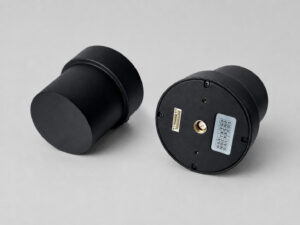
Because the HM-D20 combines the GNSS module and antenna, it can simplify installation by avoiding a separate external antenna. Engineers should still request the phase-center drawing, orientation requirements, connector sealing instructions, and keep-out guidance. The product FAQ states that reported latitude, longitude, and altitude correspond to the RTK antenna phase center. Include that detail in the aircraft configuration and mapping documentation.
Flight-Controller and Software Integration
Electrical Interface
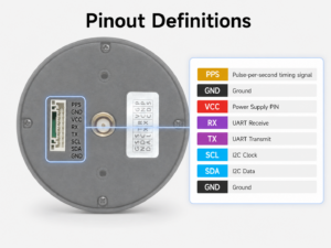
The HM-D20 uses a TTL-level UART interface at 115200 bps. Confirm the logic voltage before wiring. “TTL” alone does not prove whether the equipment uses 3.3 V or 5 V signaling. A TTL UART must not be connected directly to an RS-232 electrical interface without the correct level conversion.
Data Routing
The principal data flows are NMEA 0183 position output from the rover to the flight controller or companion computer, and RTCM correction input from a base station, telemetry radio, modem, network client, or forwarding path. Verify pinout, port direction, grounding, data framing, flow control, cable integrity, and whether the aircraft provides enough independent UART ports.
PX4 Connection
The supplied product guidance states that the RTK module can be connected to the GPS1 or GPS2 port on a Pixhawk flight controller, using the appropriate GPS1 communication cable, followed by the required parameter configuration. Exact settings depend on the flight-controller model, PX4 release, receiver mode, serial port, and correction path, so follow the current user guide rather than applying unverified parameters.
Health Monitoring and Software Resources
A robust integration should expose solution type, satellite count, correction age, horizontal and vertical accuracy estimates, and communication health where available. The flight controller should have defined behavior for loss of fixed RTK during takeoff, mission flight, landing, and return-to-home.
Product information reports ROS, Python, and C++ demonstrations for parsing and integration. Engineers can review the HM-D20 product page and the HM-D20 receiver module documentation. Before freezing the design, request the current protocol documentation, sample code, supported SDK resources, connector pinout, and configuration guide.
HM-D20 Helical Antenna RTK Module Specifications
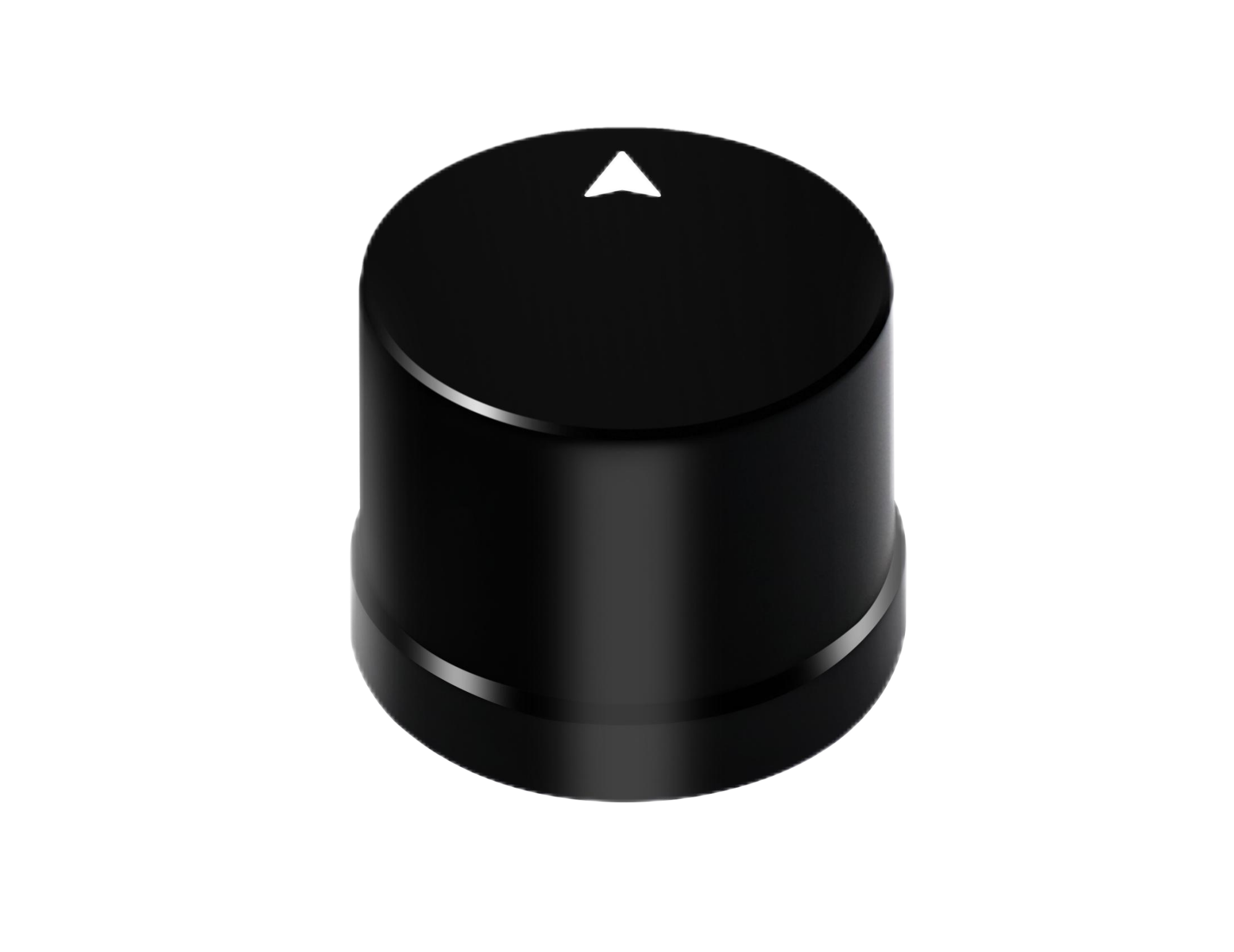
The HM-D20 is an integrated GNSS receiver and helical antenna module designed for UAVs, unmanned vehicles, ships, robotics, and other positioning systems. Its integrated design means that a separate external GNSS antenna is not required for the standard installation. The module is intended to support high-precision positioning while simplifying mechanical integration.
| Specification | Published value | Engineering significance |
|---|---|---|
| Frequency bands | GPS L1/L5; BeiDou B1/B2A/B2I; GLONASS G1; Galileo E1/E5; QZSS L1/L5; IRNSS L5 | Multi-constellation and multi-frequency tracking for broader signal availability. |
| Horizontal RTK accuracy | 1 cm + 1 ppm | Rover positioning specification under suitable RTK conditions. |
| Vertical RTK accuracy | 1.5 cm + 1 ppm | Vertical rover positioning specification under suitable RTK conditions. |
| Navigation protocol | NMEA 0183 output | Provides standardized positioning messages to a controller or computer. |
| Correction input | RTCM input at rover side | Allows the rover to receive real-time correction data. |
| Serial baud rate | 115200 bps | Must match the configured UART on the connected controller. |
| Interface | TTL-level UART | Logic voltage and pinout must be verified before wiring. |
| Dimensions | Φ44 × 37 mm | Relevant to mounting clearance and payload-envelope design. |
| Timing synchronization accuracy | 20 ns | Potentially useful for synchronized sensing; implementation details should be confirmed. |
| L1/L5 GNSS antenna system | At least 40 dB high gain | Published antenna-system value; measurement definition should be confirmed. |
| Operating temperature | -40 °C to 85 °C | Supports operation across a wide published temperature range. |
| Ingress protection | IP67 | Indicates dust protection and resistance to temporary water immersion under test conditions. |
View Product Details & Pricing ➔
Before procurement, confirm the module weight, supply voltage, current consumption, navigation update rate, RTCM versions, raw-data availability, connector pinout, timing connector, vibration limits, included cables, and any required base-station accessories. The published dimensions and environmental ratings are useful for initial design, but a complete airframe qualification requires these additional details.
The HM-D20 is supported by a manufacturer focused on perception and positioning modules for robots and UAVs. Available support includes independent research and development, professional technical assistance for integration, direct manufacturing, stable in-house supply, and customized OEM/ODM options. These capabilities can be relevant when a drone manufacturer needs a repeatable supply source or application-specific integration guidance.
Recommended RTK Drone Deployment Workflow
- ⚙️ Define the required horizontal, vertical, absolute, and relative accuracy.
- ⚙️ Identify the project datum, map projection, geoid model, and output format.
- ⚙️ Choose a local base station or compatible NTRIP service.
- ⚙️ Confirm frequency, constellation, RTCM, NMEA, electrical, and flight-controller compatibility.
- ⚙️ Measure module dimensions, mass, power demand, and center-of-gravity impact.
- ⚙️ Design the antenna location and document phase-center lever arms.
- ⚙️ Configure communication at 115200 bps and verify valid message parsing.
- ⚙️ Test correction delivery and monitor fixed, float, and standalone states.
- ⚙️ Conduct a static open-sky test followed by a powered-airframe electromagnetic-interference test.
- ⚙️ Fly over surveyed checkpoints and compare both horizontal and vertical residuals.
- ⚙️ Validate camera timing, calibration, image quality, overlap, and processing settings.
- ⚙️ Define operational thresholds for correction age, fix loss, and mission continuation.
- ⚙️ Archive base, rover, event, telemetry, and processing records for traceability.
Commissioning should use independent checkpoints rather than only the same control points used to constrain the model. That approach tests the whole system, including the base coordinate, receiver, camera, event timing, lever arms, coordinate transformations, and mapping software.
Common RTK Failure Modes
The Receiver Never Reaches RTK Fixed
Potential causes include incompatible RTCM messages, excessive baseline length, poor satellite geometry, an obstructed sky view, incorrect serial routing, stale corrections, or severe radio interference. Confirm that correction messages are reaching the rover before changing navigation parameters. Check the correction age, message type, satellite visibility, antenna location, and solution status.
The Solution Is Fixed but Globally Shifted
Likely causes include an incorrect base coordinate, wrong datum, unsuitable NTRIP mountpoint, geoid confusion, or a transformation error. A fixed solution indicates resolved ambiguities, not necessarily a correct project reference. Compare the result with an independent known point and review the complete coordinate chain.
The Fix Drops When Motors Start
Investigate electromagnetic interference from ESCs, power converters, wiring, transmitters, and grounding. Compare signal and fix metrics with propulsion disabled, the aircraft armed, and motors operating at different throttle levels. Also inspect antenna clearance from carbon fiber, batteries, and high-current conductors.
The Flight Path Is Accurate but the Map Is Not
Check camera calibration, event timing, geotag interpolation, shutter behavior, image overlap, ground sampling distance, motion blur, lever arms, and photogrammetry settings. A precise aircraft trajectory cannot compensate for poor images or incorrect camera-event association.
Altitudes Do Not Match Local Elevations
Determine whether the receiver outputs ellipsoidal height while the project expects orthometric height. Apply the correct geoid model and coordinate transformation rather than adding an undocumented constant offset. Document the vertical reference used in the field, processing software, and final export.
NMEA Data Appears Corrupted
Check baud rate, logic voltage, ground reference, framing settings, cable integrity, sentence length, parser capacity, and update rate. Confirm that a TTL signal has not been connected to an RS-232 port. Use a serial analyzer or controlled test fixture where necessary.
Engineering Procurement Checklist
- ✅ Required constellations and exact frequency bands
- ✅ Horizontal and vertical accuracy specifications
- ✅ Time to first fix and RTK convergence behavior
- ✅ Supported RTCM versions and message types
- ✅ Maximum correction age and recommended baseline
- ✅ NMEA sentences and navigation update rate
- ✅ Raw-observation or PPK logging support
- ✅ Timing output, event input, and synchronization behavior
- ✅ UART logic voltage, pinout, and baud rate
- ✅ Input-voltage range and polarity protection
- ✅ Typical and peak power consumption
- ✅ Dimensions, weight, mounting pattern, and connector clearance
- ✅ Antenna orientation and phase-center documentation
- ✅ IP rating, temperature range, vibration, and shock limits
- ✅ Flight-controller and PX4 compatibility
- ✅ ROS, Python, C++, SDK, and protocol resources
- ✅ Included cables and base-station compatibility
- ✅ Warranty, lead time, OEM/ODM support, and technical support
Engineers evaluating an integrated receiver can review the HM-D20 Helical Antenna RTK Module and request current integration documentation before procurement. Existing customers can use My Account to manage account activity, while approved products can be reviewed in the shopping cart before checkout.
Frequently Asked Questions
How Accurate Is RTK Drone Mapping in Real-World Conditions?
Does an RTK-Equipped Drone Still Need a Local Base Station?
What Should Engineers Check Before Adding RTK to a Custom or Mini Drone?
Can RTK Eliminate Ground Control Points?
What Happens If the Drone Loses RTK Corrections During Flight?
Is Multi-Frequency GNSS Important for Drone RTK?
Can One RTK Module Support Both Navigation and Mapping?
📚 References & Further Reading
-
- Industry Standard: CHC Navigation
- Complementary Perception Technology: Ouster lidar solutions
- Product Documentation: HM-D20 GNSS RTK Receiver Module
- Product Page: HM-D20 Helical Antenna RTK Module






