Industrial IMU for Robotics and UAVs: How to Choose High-Precision Motion Sensing
An industrial IMU is not just a small board that reports acceleration and rotation. In a robotic arm, autonomous vehicle, UAV, or stabilization platform, the IMU becomes part of the machine’s motion reference. Its noise, bias behavior, bandwidth, output rate, temperature response, interface, and installation quality all affect how accurately the system estimates attitude, detects movement, stabilizes a payload, or maintains navigation during a sensor outage.
Here’s the deal: a low-cost consumer sensor can look fine on the bench and still become unreliable once it sees motor vibration, gearbox harmonics, temperature changes, rapid maneuvers, or long operating hours. Choosing an industrial IMU means looking beyond one impressive accuracy number. You need to consider gyro bias instability, angular random walk, accelerometer bias, velocity random walk, bandwidth, output timing, calibration method, temperature range, communication interface, mechanical mounting, and fault monitoring as one complete system.
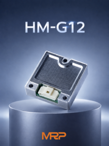
The HM-G12 Industrial High Precision IMU is a compact 6-axis MEMS module intended for drones, robotics, and industrial machines. Its listed specifications include 200Hz gyroscope and accelerometer bandwidth, a product-stated 1000Hz output rate, a ±16g acceleration range, factory calibration across -40°C to +85°C, and a 30mm × 30mm × 10.6mm form factor.
That combination can be useful, but engineers should still validate the module in the actual machine. A good datasheet is the starting point—not the final test report. In the shop, the mounting bracket, cable routing, power supply, vibration spectrum, timestamp behavior, and estimator often determine whether the IMU performs as expected.
Table of Contents
- 👉 What Is an Industrial IMU?
- 👉 How an IMU Measures Motion
- 👉 Key IMU Performance Specifications
- 👉 How to Choose an IMU for Robotics
- 👉 How to Choose an IMU for UAVs and Drones
- 👉 Temperature, Vibration, and Environmental Performance
- 👉 Electrical and Mechanical Integration
- 👉 HM-G12 Industrial High Precision IMU Specifications
- 👉 Where the HM-G12 Fits Best
- 👉 IMU Integration and Validation Checklist
- 👉 Industrial IMU FAQ
What Is an Industrial IMU?
An inertial measurement unit, or IMU, is an electronic module that measures angular motion and specific force. A conventional 6-axis IMU combines three gyroscopes with three accelerometers. The gyroscopes measure angular velocity around the X, Y, and Z axes. The accelerometers measure specific force along those same three axes. Internal electronics condition the signals, apply calibration coefficients, compensate for known errors, and send the resulting data to a host controller.
An industrial-grade IMU is built for more demanding operating conditions than a basic consumer motion sensor. The usual priorities are repeatable performance, documented error characteristics, temperature compensation, stable communications, mechanical robustness, and predictable behavior inside a control or navigation system. The word “industrial” is not a substitute for a complete specification. Look closely at bias, noise, bandwidth, calibration conditions, timing, operating limits, and qualification data for the exact part number.
Industrial IMU Versus Consumer-Grade IMU
Consumer MEMS sensors are generally optimized for low cost, small size, and high-volume products such as phones, wearables, and entertainment devices. An industrial IMU is more likely to provide the performance information needed to model drift, evaluate temperature behavior, and integrate the sensor into an embedded control architecture. It may also offer a more suitable connector, mounting arrangement, data protocol, or diagnostic function.
The distinction matters in autonomous robots, UAV flight controllers, mobile mapping platforms, gimbals, and industrial motion equipment. These systems may run for hours, experience motor and gearbox vibration, and depend on the IMU during a temporary loss of GNSS, visual features, wheel traction, or another external reference.
What an IMU Can and Cannot Measure
An IMU measures angular rate and specific force; it does not directly measure absolute position. A navigation computer estimates orientation, velocity, and position by integrating the measurements and combining them with external observations. Those observations may come from GNSS, cameras, lidar, wheel encoders, radar, magnetometers, barometers, or other reference sensors.
This limitation is fundamental to inertial sensing. Even an excellent MEMS device accumulates error because small bias and noise terms are integrated over time. A high-precision IMU slows the growth of uncertainty, particularly during short external-sensor outages, but it remains one part of a complete estimation and control system.
Got tired of bulky LiDAR setups for simple depth tasks
How an IMU Measures Motion
The measurement process begins with MEMS sensing elements that respond to angular rate and acceleration. Signal-conditioning electronics convert the sensor response into usable electrical data. An internal MCU may then apply factory calibration, temperature compensation, axis alignment correction, filtering, and data formatting before sending measurements to the host system.
Gyroscope Measurement
A gyroscope measures angular velocity. When a vehicle rotates around one of its axes, the gyro reports the rate of that rotation. Software integrates angular-rate data to estimate a change in orientation. A small constant offset in the gyro output can therefore become a growing attitude error, which is why bias behavior is one of the most important specifications for a robotics IMU or UAV IMU.
Angular random walk describes the contribution of random gyro noise to angle uncertainty over time. It is commonly expressed in degrees per square root hour. Lower angular random walk generally indicates cleaner short-term angular-rate data, although the result also depends on sampling, filtering, vibration, timing, and estimator design.
Bias instability describes slow, low-frequency variation in the apparent zero-rate output. Engineers often evaluate it with Allan deviation or a similar stability analysis. Bias stability may be reported as a related application or test metric, but the exact definition and test conditions should be confirmed with the manufacturer.
Orthogonality error and cross-axis coupling describe imperfections in the relationship between sensing axes. Motion on one axis can appear partly on another when the axes are not perfectly perpendicular. This matters in precision stabilization, robotic joint control, platform alignment, and dynamic UAV maneuvers.
Accelerometer Measurement
An accelerometer measures specific force, including the effect of gravity and the forces produced by vehicle or machine motion. Accelerometer data supports tilt estimation, motion detection, velocity estimation, dead reckoning, and inertial navigation. Because gravity is always present, the estimator must account for platform attitude when interpreting acceleration.
The accelerometer range is the maximum positive and negative acceleration the device can measure before saturating. A ±16g range provides headroom for dynamic movement, vibration, impacts, and rapid maneuvers, but range alone does not determine precision. Review it together with noise, resolution, bias, scale-factor error, bandwidth, and expected shock levels.
Velocity random walk characterizes how accelerometer noise contributes to velocity uncertainty over time. Accelerometer bias instability and bias stability describe slowly changing errors that can become especially important when acceleration is integrated for dead reckoning or navigation.
Sensor Bandwidth Versus Output Rate
Sensor bandwidth and output rate are related but different specifications. Bandwidth describes the frequency range over which the physical sensor and signal-processing chain respond to motion. Output rate describes how frequently the module sends data to the host controller.
The HM-G12 specifications identify a 200Hz gyroscope bandwidth and a 200Hz accelerometer bandwidth. The product overview separately identifies a 1000Hz output rate. A 1000Hz stream should not automatically be interpreted as 1000Hz physical measurement bandwidth. Depending on the architecture, the output may contain filtered, processed, oversampled, or repeatedly reported data. During integration, confirm latency, filtering, data freshness, timestamp behavior, and frequency response.
Key IMU Performance Specifications
Comparing industrial IMUs requires a complete view of error sources rather than selecting a device because of one headline number. The useful specifications describe how the sensor behaves during stationary operation, dynamic movement, temperature changes, and periods without external navigation updates. Always review the units and test conditions behind every value.
Bias Instability and Bias Stability
Bias is the difference between the sensor’s reported output and the expected output when the actual input is known. Gyroscope bias is often discussed in degrees per hour, while accelerometer bias may be expressed in milligals or mg. Bias can change with temperature, supply conditions, vibration, mechanical stress, aging, and the sensor’s internal operating state.
Gyroscope bias directly affects attitude drift. Accelerometer bias affects velocity and position drift after integration. Low bias is valuable during stationary alignment, slow robotic movement, hovering, stabilization, and short periods when GNSS or another external reference is unavailable. Check whether a published number is typical, maximum, or guaranteed, and review the measurement conditions used to obtain it.
For the HM-G12, the detailed specifications list gyro bias instability of ≤ 1.4°/h, gyro bias stability of ≤ 4°/h, accelerometer bias instability of 0.016mg, and accelerometer bias stability of 0.055mg. The product overview also presents 1.4°/h as a typical gyro bias-instability callout. These values should be considered alongside calibration, environmental, and system-integration conditions.
Angular Random Walk and Velocity Random Walk
Random-walk metrics characterize stochastic noise rather than a fixed offset. HM-G12 lists a gyroscope angular random walk of ≤ 0.15°/√h and an accelerometer velocity random walk of 0.018m/s/√h. Lower random-walk values generally support a cleaner short-term estimate, but actual navigation performance depends on the estimator, update frequency, sensor fusion, vibration environment, and timing accuracy.
A low-noise IMU can still produce poor results when installed on a flexible bracket or when its timestamps are not aligned with camera, GNSS, or wheel-encoder data. Conversely, a well-designed estimator and rigid installation can help the system make better use of the available sensor performance.
Orthogonality Error and Cross-Axis Coupling
Real sensing axes are not perfectly independent. When the platform moves along one axis, a small component may appear on another because of axis misalignment, structural effects, calibration residuals, or sensor cross-axis sensitivity. This can affect robotic arms, gimbals, mapping equipment, and UAV control systems that depend on accurate separation of motion components.
HM-G12 lists gyroscope orthogonality error of ≤ 0.05°. The product overview also uses a ≤0.05° gyro cross-axis-coupling callout. These terms are related to multi-axis error but should not be assumed to represent identical test methods unless the manufacturer confirms the definition. When comparing products, request the relevant test conditions and calibration model.
Range, Resolution, Noise, and Dynamic Response
Range prevents saturation during high-dynamic events. Resolution describes the smallest practical measurement increment. Noise influences short-term stability and control smoothness. Dynamic response determines whether fast motion is captured without excessive attenuation or phase delay. A suitable industrial IMU balances all four characteristics with the application’s motion profile.
How to Choose an IMU for Robotics
Robotics applications range from slow precision manipulation to high-speed autonomous mobility. The correct robotics IMU should be selected according to the robot’s motion, vibration, control-loop frequency, navigation strategy, and physical installation—not by product category alone.
Mobile Robots and Autonomous Ground Vehicles
Mobile robots often need stable tilt estimation, low drift during slow movement, and robust performance around wheel, motor, gearbox, or chassis vibration. The IMU may be fused with wheel odometry, lidar, cameras, GNSS, or radar. Its timestamp behavior and coordinate-frame definition are therefore just as important as the raw sensor figures.
Installation near the vehicle’s center of motion can simplify modeling, although the best location depends on the estimator and mechanical design. If the IMU is far from the center of rotation, lever-arm effects may need to be included. Rigid mounting helps maintain a consistent relationship between the sensor axes and the robot body frame.
Robotic Arms and Manipulators
A robotic arm may use an IMU for tool orientation, collision detection, abnormal-motion monitoring, dynamic modeling, mobile-manipulator state estimation, or end-effector stabilization. Cable movement and connector strain can introduce intermittent faults that look like sensor noise. Secure the module to a mechanically stable surface, and document the sensor-to-tool coordinate transform in software and production procedures.
Industrial Automation and Motion Platforms
Industrial motion platforms benefit from predictable output timing, low latency, temperature stability, electrical-noise tolerance, and clear startup behavior. Fault status and invalid-data handling should be designed into the host controller instead of treated as optional features. Before procurement, confirm the communication protocol, packet structure, update timing, initialization requirements, and environmental qualification.
For examples of wider industrial deployment contexts, review the industrial robotics and automation applications available for related sensing and control systems.
How to Choose an IMU for UAVs and Drones
UAV IMU selection depends on aircraft dynamics, airframe vibration, control-loop frequency, mass, power consumption, temperature exposure, and the availability of GNSS or other navigation references. A drone inertial measurement unit must deliver angular-rate and acceleration data quickly enough for stabilization while remaining predictable around motor and propeller vibration.
Flight-Control Requirements
Flight controllers generally require fast angular-rate measurements for attitude stabilization. Low latency between physical motion and control output matters during rapid maneuvers or when controlling a gimbal or payload. The acceleration range must accommodate takeoff, landing, maneuvering, turbulence, vibration, and possible impact events without saturation.
HM-G12’s product overview identifies a 1000Hz output rate, which may be relevant to systems requiring frequent control updates. Evaluate this separately from the specified 200Hz gyroscope and accelerometer bandwidth. Flight-control engineers should verify packet timing, data freshness, filtering, delay, axis orientation, and compatibility with the intended flight-control software.
Navigation and GNSS-Denied Operation
An IMU can bridge short gaps in GNSS or external positioning, but inertial drift increases as the outage continues. Lower bias and noise characteristics improve short-term state propagation, especially when the UAV combines inertial data with GNSS, visual-inertial odometry, lidar odometry, barometric altitude, radar, or another external reference.
Install the IMU close to the airframe’s intended reference point and isolate it from problematic vibration without allowing excessive flexibility. Characterize the complete aircraft, including motors, propellers, flight-controller mounts, wiring, enclosure, and payload. Laboratory performance alone does not guarantee flight performance.
UAV Size, Mass, and Power
HM-G12 measures 30mm × 30mm × 10.6mm, weighs 14g, and has a specified operating current of ≤31mA. Its input voltage is DC 5 ±0.5V. These characteristics may support compact UAV and robotic designs, but check regulator capacity, startup behavior, connector retention, signal-level compatibility, electromagnetic noise, and thermal conditions.
Temperature, Vibration, and Environmental Performance
Temperature Compensation
MEMS gyroscopes and accelerometers can change their bias, scale factor, and alignment as temperature changes. A wide operating-temperature specification is useful, but full-temperature calibration provides additional information about how those changes are characterized and compensated. This distinction matters for outdoor UAVs, autonomous vehicles, industrial equipment, and machines exposed to thermal cycling.
HM-G12 is specified for operation from -40°C to +85°C and storage from -40°C to +85°C. The product information states that each module is factory calibrated across the full operating temperature range. Customers requiring quantified residual error should request calibration reports, test conditions, temperature steps, and clarification of whether published accuracy values are typical or guaranteed limits.
Vibration and Mechanical Resonance
Motor vibration, propeller imbalance, gear mesh, chassis resonance, and structural coupling can degrade inertial measurements. Vibration may be filtered electronically, reduced mechanically, or addressed through a combination of both methods. Identify the dominant vibration frequencies and verify that they do not cause sensor saturation, aliasing, excessive control-loop noise, or a mechanical resonance at an undesirable frequency.
Soft mounting is not automatically the best solution. An overly flexible mount can allow the IMU to move relative to the vehicle body, creating phase lag and inaccurate motion information. The appropriate mounting strategy depends on the vibration spectrum and control architecture. HM-G12’s screw-mounting concept supports stable mechanical installation, but the final mounting design must be validated in the completed machine.
Fault Monitoring and Reliability
The supplied HM-G12 product information describes built-in redundant architecture, continuous sensor-status monitoring, and fault-detection functionality. These features are intended to improve system-level reliability by helping the host detect abnormal sensor conditions. They should not automatically be interpreted as certification or compliance with a specific functional-safety standard.
Before using the module in a safety-related function, review the manufacturer’s safety documentation, diagnostic coverage, failure response, redundancy behavior, and system-level compliance requirements. A reliable industrial IMU is one part of a wider safety architecture that includes power, communication, software, actuator control, and supervisory monitoring.
Electrical and Mechanical Integration
UART Interface and Voltage Levels
HM-G12 provides one external UART data interface by default. It uses a 10-pin connector and a 3.3V digital signal level. The specified input voltage is DC 5 ±0.5V, and the operating current is ≤31mA. The supply voltage and logic signal level are separate requirements: a 5V supply input does not mean that the host should drive 5V UART logic into the module.
The host controller should provide a stable supply, a compatible logic-level interface, and a common ground reference. Check power integrity during startup, high-rate transmission, and nearby actuator operation. A regulator that appears adequate under average load may still create disturbances if wiring, grounding, or transient response is poor.
UART Integration Checklist
- ⚙️ Confirm the TX and RX pin assignments before applying power.
- ⚙️ Confirm a common ground between the IMU and host controller.
- ⚙️ Verify baud rate, frame format, parity, and stop-bit settings.
- ⚙️ Confirm startup delay, reset behavior, and initialization commands.
- ⚙️ Validate packet length, checksum, units, axis order, and sign convention.
- ⚙️ Check timestamp behavior and determine whether timestamps are generated by the sensor or host.
- ⚙️ Confirm the configured output rate, filtering, and data-validity behavior.
- ⚙️ Use a logic analyzer during initial system bring-up.
- ⚙️ Test cable disconnect, power cycling, brownout, and reconnection behavior.
- ⚙️ Implement communication timeout and invalid-data handling in the host controller.
Why SPI May Not Work During Bring-Up
SPI integration failures commonly result from incorrect chip-select timing, incompatible clock polarity or phase, voltage-level mismatch, wiring errors, missing initialization commands, unsupported SPI mode, incorrect register addressing, or the absence of a common ground. A logic analyzer can show whether the controller is generating clock pulses, selecting the device correctly, and receiving a valid response.
HM-G12 uses UART by default, which may simplify integration with embedded controllers, Raspberry Pi systems, Jetson platforms, ROS-based systems, and custom robotic hardware, subject to software-driver compatibility. UART still requires careful validation of packet protocol, baud rate, axis convention, checksum, timing, and error handling.
Mounting and Coordinate Frames
Mount the module rigidly on a flat, stable surface. Record its axis orientation relative to the robot, UAV, or machine body frame and apply the correct coordinate transform in software. Confirm the right-hand coordinate convention, positive rotation direction, acceleration sign convention, and reference point used by the navigation estimator.
A compact sensor can be installed in many locations, but a convenient location is not always the best measurement location. Avoid flexing circuit boards, unsupported connectors, moving cables, and mounting surfaces that change shape under load. If the IMU is remote from the platform’s center of rotation, evaluate lever-arm effects and include them in the system model when necessary.
HM-G12 Industrial High Precision IMU Specifications

The Industrial High Precision IMU HM-G12 integrates three gyroscopes, three accelerometers, and an MCU into a compact industrial-grade module. It is designed to deliver precise motion sensing for intelligent machines, drones, robotics, autonomous platforms, stabilization systems, and industrial applications.
The module combines low-noise inertial sensing with full-temperature calibration and error-compensation algorithms. The product information highlights 1.4°/h typical gyro bias instability, 0.016mg accelerometer bias instability, ≤0.05° gyro cross-axis coupling in the product callout, a ±16g accelerometer range, and a product-stated 1000Hz output rate. Read those product highlights together with the detailed specifications below.
| Category | Parameter | Specification |
|---|---|---|
| Gyroscope | Bandwidth | 200Hz |
| Angular Random Walk | ≤ 0.15°/√h | |
| Bias Instability | ≤ 1.4°/h | |
| Bias Stability | ≤ 4°/h | |
| Orthogonality Error | ≤ 0.05° | |
| Accelerometer | Accelerometer Range | ±16g |
| Velocity Random Walk | 0.018m/s/√h | |
| Bias Instability | 0.016mg | |
| Bias Stability | 0.055mg | |
| Bandwidth | 200Hz | |
| Electrical Interface | External Data Interface | UART ×1 (Default) |
| Operating Current | ≤ 31mA | |
| Input Voltage | DC 5 ± 0.5V | |
| Interface Type | 10-pin connector, 3.3V digital signal level | |
| Mechanical and Environmental | Dimensions | 30mm × 30mm × 10.6mm |
| Operating Temperature | -40°C to +85°C | |
| Weight | 14g | |
| Storage Temperature | -40°C to +85°C |
HM-G12 is particularly relevant when a design requires high-precision 6-axis inertial measurement, a compact installation footprint, a ±16g accelerometer range, UART communication, full-temperature calibration, high-frequency data output, and described sensor-status monitoring. The 10-pin connector, 3.3V digital signal level, and screw-mounting concept support integration into embedded control systems, provided the host hardware and mechanical design are compatible.
Where the HM-G12 Fits Best
HM-G12 can be evaluated for applications where compact dimensions, industrial temperature performance, six-axis data, and stable embedded communication are important. The final selection should be based on measured system requirements, environmental qualification, software compatibility, and complete manufacturer documentation.
| Application | Why HM-G12 May Fit | Engineering Checks |
|---|---|---|
| UAV flight control | Product-stated 1000Hz output rate, compact 14g package, and ±16g range | Verify vibration spectrum, latency, filtering, and flight-controller protocol |
| Robotic platforms | 6-axis motion data, UART interface, and compact size | Confirm coordinate-frame mapping and estimator compatibility |
| Autonomous ground vehicles | Low-bias specifications and temperature-calibrated performance | Validate drift with GNSS or odometry outages |
| Gimbals and stabilization | Gyro noise and multi-axis performance specifications | Check control-loop bandwidth and mechanical resonance |
| Industrial motion monitoring | Temperature range and described fault-detection features | Confirm environmental qualification and certifications |
| Embedded prototypes | 10-pin connector and UART integration | Confirm driver, packet format, power, and signal-level requirements |
In autonomous vehicle architectures, inertial data is often combined with external sensing. A complementary discussion of sensing in autonomous marine systems is available in this article about inertial sensing in autonomous vehicle systems.
IMU Integration and Validation Checklist
Specification Validation
- ✅ Determine whether gyro and accelerometer bias values are typical, maximum, or guaranteed.
- ✅ Request the test conditions and calibration method behind each published value.
- ✅ Separate sensor bandwidth from output rate and confirm latency.
- ✅ Check that angular random walk and velocity random walk are reported in appropriate units.
- ✅ Confirm that the ±16g range is appropriate for normal motion, vibration, and shock events.
- ✅ Verify full-temperature calibration and expected residual error across the operating range.
Electrical Validation
- ✅ Confirm that the host accepts a 3.3V digital signal.
- ✅ Provide the specified DC 5 ±0.5V input.
- ✅ Allow sufficient current capacity beyond the stated ≤31mA operating current.
- ✅ Verify UART packet protocol, baud rate, checksum, and output configuration.
- ✅ Test startup, reset, power cycling, brownout, and communication recovery.
Mechanical Validation
- ✅ Confirm compatibility with the 30mm × 30mm × 10.6mm package.
- ✅ Provide a rigid mounting surface for the 14g module.
- ✅ Protect the 10-pin connector from vibration and cable strain.
- ✅ Record sensor axis orientation and mounting tolerances.
- ✅ Measure vibration at the final installation location.
System-Level Validation
Run static bias tests, six-position accelerometer tests, stationary gyro tests, thermal tests, vibration tests, and communication-integrity tests. Compare inertial output against an independent reference where possible. Verify estimator behavior during GNSS, lidar, camera, or wheel-odometry dropouts. Confirm that invalid packets, communication timeouts, sensor faults, and power interruptions are handled safely by the host controller.
Teams selecting complementary optical sensors may also benefit from reviewing this DToF and iToF sensor selection guide. Time-of-flight sensors, cameras, lidar, GNSS, and wheel encoders can provide external observations that help correct the drift inherent in standalone inertial integration.
Industrial IMU FAQ
What should I look for when choosing an industrial IMU for robotics or UAVs?
Is there a reliable high-accuracy IMU under $1,000?
Why might an IMU fail to respond over SPI, and can UART be easier to integrate?
Is a 1000Hz IMU output rate the same as 1000Hz bandwidth?
What does gyro bias instability mean for UAV navigation?
How does accelerometer bias affect a mobile robot?
Should an IMU be soft-mounted to isolate vibration?
Can an industrial IMU replace GNSS, lidar, or visual odometry?
What does full-temperature calibration provide?
What should be tested before deploying an IMU in production?
📚 References & Further Reading
- ✅ Industry Standard: Xsens inertial sensing and motion-tracking resources
- ✅ Applications: Industrial robotics and automation applications
- ✅ Product: HM-G12 Industrial High Precision IMU product page