LiDAR with Drone: How to Choose a Lightweight Sensor for UAV Mapping, Surveying, and Obstacle Avoidance
Adding lidar with drone systems can make a UAV a whole lot smarter. You get better distance sensing, obstacle detection, altitude control, terrain awareness, and inspection capability. But here’s the deal: the wrong LiDAR can turn a good drone project into a heavy, power-hungry, hard-to-debug mess. I’ve seen teams bolt on sensors that looked great on paper, only to find out the UAV couldn’t carry the payload, the battery sagged, the mount vibrated, or the data pipeline choked before the first useful flight test.
Many drone teams start by searching for “drone LiDAR” and immediately run into expensive survey-grade payloads built for professional aerial mapping. Those systems have their place. No question. But not every UAV project needs a full mapping stack with RTK, IMU, calibration software, and post-processing. Sometimes the real need is a compact depth sensor for obstacle avoidance, altitude hold, terrain following, inspection standoff control, indoor navigation, or embedded perception development.
Table of Contents
- 👉 What Does LiDAR with Drone Mean?
- 👉 How LiDAR Works on UAV Platforms
- 👉 Drone LiDAR for Mapping vs Obstacle Avoidance
- 👉 Types of LiDAR Sensors Used with Drones
- 👉 Key Specifications When Choosing UAV LiDAR
- 👉 Why Lightweight LiDAR Matters for Small Drones
- 👉 Integration Workflow: Flight Controllers, Companion Computers, and SDKs
- 👉 Reality Check: Can Lightweight LiDAR Do Land Surveying?
- 👉 Recommended Lightweight LiDAR Module for UAV Development: DTOF Solid State LiDAR HM-LD1
- 👉 Industrial Applications for LiDAR with Drone Systems
- 👉 Buying Checklist for UAV LiDAR Selection
- 👉 FAQ: LiDAR with Drone
What Does LiDAR with Drone Mean?
LiDAR with drone means mounting or integrating a LiDAR sensor on an unmanned aerial vehicle so the aircraft can measure distance, perceive surfaces, detect obstacles, or collect 3D spatial information. The drone provides the mobility. The LiDAR provides active depth sensing. Unlike a passive camera that depends on ambient light and visual texture, LiDAR emits light and measures the returned signal to calculate distance. That makes it useful when a UAV needs to understand geometry, not just capture photos or video.
Look, the phrase “drone LiDAR” gets used for several very different systems. At one end are professional aerial mapping payloads that combine high-performance LiDAR scanners, RTK/GNSS, IMU systems, calibration workflows, and post-processing software. At the other end are lightweight depth LiDAR modules designed for local perception, obstacle avoidance, altitude hold, terrain following, inspection support, and robotics development. Both categories use LiDAR technology, but they are not interchangeable.
For UAVs, LiDAR can support 3D mapping, distance measurement, obstacle detection, altitude hold, terrain following, indoor navigation, SLAM research, inspection standoff control, and robotic vision development. A heavy survey payload is very different from a compact 28 g solid-state depth LiDAR module. The right choice depends on the mission, the aircraft, the payload capacity, the power budget, the required range, the output data format, and whether the final deliverable is local perception data or survey-grade georeferenced mapping data.
For applications requiring precise georeferencing, it is also useful to understand what RTK is and how centimeter-level GPS navigation works. RTK is not mandatory for every drone that uses LiDAR, but it becomes extremely important when the goal is accurate mapping, surveying, or geospatial point-cloud generation.
This guide walks through how LiDAR works on drones, when to choose survey-grade payloads versus lightweight dToF solid-state sensors, and which specifications matter most when evaluating range, accuracy, field of view, resolution, frame rate, power consumption, interfaces, and SDK support. It also includes a UAV-friendly example: the DTOF Solid State LiDAR HM-LD1, a 28 g compact module with UART, UDP, and UVC interfaces, real-time depth images, and 3D point-cloud output for UAV perception and robotic vision development.
How LiDAR Works on UAV Platforms
Basic LiDAR Measurement Principle
LiDAR is an active optical sensing technology. A LiDAR emitter sends a light pulse or modulated light signal toward a target. The receiver detects the light reflected from an object, surface, ground plane, wall, bridge, tree, vehicle, shelf rack, or other structure. The sensor then calculates distance based on the timing or characteristics of the returned signal. In Direct Time-of-Flight, commonly called dToF, the system measures the travel time of emitted light pulses. Since light travels at a known speed, very small timing differences can be converted into distance measurements.
Modern solid-state dToF modules may use SPAD technology, or single-photon avalanche diode detection, to sense very small amounts of returned light. In the shop, that matters because compact sensors don’t have unlimited laser power, cooling, or board space. They need to detect reflections from different surfaces while staying inside tight power, size, and thermal limits. For drone integration, this measurement principle is attractive because it can provide direct distance information without relying only on image texture, stereo matching, or barometric altitude estimation.
For broader industry context on LiDAR technology and industrial perception, manufacturers such as Blickfeld provide additional background on LiDAR sensing approaches. When selecting LiDAR for UAVs, though, the important question is not only how LiDAR works in theory. The real question is how the sensor performs under your aircraft’s vibration, sunlight, speed, mounting angle, electrical noise, and processing constraints.
What Data Does Drone LiDAR Produce?
LiDAR sensors can produce different levels of data. A basic rangefinder may output a single distance value, which is useful for simple altitude measurement or direct distance checking. A depth LiDAR module provides a depth image, where each pixel contains a distance value. A more advanced scanning or depth system can also generate a 3D point cloud, which represents measured points in three-dimensional space.
For UAV perception, depth images and point clouds are especially useful. A depth image can be processed using region-of-interest logic to determine whether an obstacle is in the flight path. A point cloud can be visualized, filtered, segmented, or used in SLAM and navigation research. For a module like the DTOF Solid State LiDAR HM-LD1, real-time depth images and 3D point-cloud data help developers build embedded perception systems for obstacle logic, distance detection, smart inspection, and robotic vision workflows.
Why Active Depth Sensing Matters on Drones
Drones operate in dynamic environments where fast and reliable distance information can improve safety and autonomy. Cameras provide rich visual information, but they can struggle when surfaces lack texture, lighting changes quickly, or depth must be measured directly. Ultrasonic sensors can be useful for short-range measurement, but they are limited by beam shape, range, acoustic interference, and surface characteristics. LiDAR provides direct optical distance measurement, making it valuable for UAVs that must detect nearby structures, maintain a standoff distance, follow terrain, or operate in GPS-denied environments.
Active depth sensing is not a complete autonomy solution by itself. A well-designed drone system still needs sensing, processing, control logic, filtering, safety constraints, and fail-safe behavior. LiDAR gives the aircraft another layer of perception. It tells the system where nearby surfaces and obstacles are located relative to the vehicle, but the control architecture must still decide what to do with that information.
Drone LiDAR for Mapping vs Obstacle Avoidance
Survey-Grade Drone LiDAR
Survey-grade drone LiDAR is designed to generate accurate georeferenced point clouds for professional mapping, land surveying, forestry analysis, corridor mapping, construction measurement, mining, and infrastructure documentation. These systems usually require a full sensor stack, not only a LiDAR sensor. A professional payload commonly includes a high-density LiDAR scanner, GNSS/RTK or PPK positioning, an IMU for orientation, precise timestamp synchronization, calibration tools, ground control or check points, and processing software.
These systems are powerful, but they are also heavier, more expensive, and more complex than a compact UAV perception module. They may require larger drones, careful flight planning, post-processing expertise, and mission-specific calibration. If your deliverable is a certified survey dataset, contour map, georeferenced point cloud, or engineering-grade terrain model, you should evaluate a complete mapping payload rather than assuming that any LiDAR module will produce survey-ready results.
Here’s the practical way to think about it: survey-grade LiDAR is about measuring the world in a coordinate system. Lightweight perception LiDAR is about helping the drone understand what is nearby right now. Those are both valuable jobs, but they are not the same job.
Lightweight LiDAR for Obstacle Avoidance and Navigation
Lightweight LiDAR for drones is usually optimized for short-to-mid-range perception, real-time distance detection, compact mounting, low power consumption, and integration with embedded computers or flight logic. Instead of producing professional survey deliverables, these sensors support local awareness. They can help the drone detect obstacles, maintain altitude, estimate distance to a structure, support terrain following, or provide depth data for onboard algorithms.
This category is especially important for small UAV developers, research teams, embedded vision engineers, and robotics companies. A compact solid-state LiDAR can be mounted forward-facing for obstacle detection, downward-facing for altitude hold, or side-facing for inspection and wall following. When paired with a companion computer such as Raspberry Pi, Jetson, or another ARM Linux platform, the depth data can be processed into simplified safety zones or control inputs.
When You Need Which Type
| Use Case | Recommended LiDAR Type | Typical Requirements |
|---|---|---|
| Professional land surveying | Survey-grade LiDAR payload | GNSS/RTK, IMU, calibration, high-density point cloud, mapping software |
| Obstacle avoidance | Lightweight depth LiDAR | Real-time distance data, compact size, low latency, UAV-friendly weight |
| Altitude hold | Downward-facing range or depth LiDAR | Reliable ground distance, fast response, stable output |
| Indoor drone navigation | Solid-state LiDAR or depth module | Short-range depth sensing, SLAM support, onboard processing compatibility |
| Bridge, dam, or infrastructure inspection | Lightweight perception LiDAR or mapping payload depending on deliverable | Obstacle awareness, distance measurement, inspection standoff control |
Types of LiDAR Sensors Used with Drones
Mechanical Scanning LiDAR
Mechanical scanning LiDAR uses rotating or moving components to scan across a scene. These systems can provide broad coverage and are widely used in mapping, robotics, autonomous vehicles, and industrial perception. For drone applications, mechanical scanners can be useful when wide-area point-cloud collection is required. However, they can also be heavier, more power-hungry, and more mechanically complex than solid-state modules. UAV vibration, shock, and long-term reliability should be considered when selecting any sensor with moving parts.
Mechanical scanning LiDAR can be the right choice for mapping, but it demands respect. The mount needs to be rigid. The power system needs margin. The data pipeline needs enough bandwidth. The drone needs to fly in a way that supports clean point-cloud generation. If any one of those pieces is weak, the final data quality suffers.
Solid-State LiDAR
Solid-state LiDAR does not depend on a large rotating mechanism. This can make it more suitable for compact platforms where mechanical simplicity, weight, power consumption, and robustness are important. For small UAVs, a compact solid-state LiDAR can be easier to integrate into a custom frame or sensor bay. It can also support depth imaging and real-time perception tasks without requiring a large scanning payload.
Solid-state LiDAR is especially relevant for drone obstacle avoidance, distance measurement, indoor navigation, terrain awareness, and embedded robotics development. It is not automatically equivalent to a survey payload, but it can be a practical sensing layer for UAV systems that need local depth perception.
dToF LiDAR
Direct Time-of-Flight LiDAR measures the actual travel time of emitted light pulses. This makes it well suited for distance measurement because the output is based on direct timing rather than purely visual inference. dToF modules can support depth images and point-cloud output, depending on their sensor architecture and processing capabilities. For drones, dToF LiDAR can support real-time awareness, obstacle-zone detection, and distance-based control logic.
In a UAV project, dToF is often attractive because the data is direct and practical. You can define a detection zone, measure minimum distance, apply filtering, and feed a simplified result into flight logic. That is exactly the kind of engineering workflow teams need when they are trying to move from bench testing to controlled flight tests.
Single-Point Rangefinders vs Depth LiDAR
A single-point rangefinder gives one distance value. This can be enough for basic altitude hold or a simple front-facing proximity alarm. A depth LiDAR provides multiple distance values across a field of view. For example, a 40 × 30 depth map contains 1,200 distance points per frame. This enables the system to detect whether an obstacle appears in the center, left, right, upper, or lower portion of the scene. For UAV perception, that spatial awareness is often more valuable than a single measurement.
Single-point sensors are easy to understand, but they can miss objects outside the beam. Depth LiDAR gives the software a small window into the scene. That makes it more useful for identifying zones, detecting edges, measuring surfaces, or deciding whether the aircraft should slow down, hold position, or move away from a structure.
Key Specifications When Choosing UAV LiDAR
Weight
Every gram matters on a UAV. Payload weight reduces flight time, increases motor load, affects stability, and may require a larger battery or frame. A professional survey LiDAR payload may be unsuitable for a small drone simply because the aircraft cannot carry it safely. A 28 g LiDAR module, by contrast, is far more realistic for lightweight UAV experiments, development platforms, and compact inspection drones. When comparing sensors, evaluate not only the LiDAR weight but also mounts, cables, regulators, companion computers, and protective housings.
In the shop, this is where many prototypes get into trouble. The sensor may weigh 28 g, but the bracket, wiring, fasteners, converter board, and enclosure add up. Always weigh the whole installed subsystem, not just the catalog part.
Power Consumption
Power consumption affects battery runtime, thermal design, regulator sizing, and total system reliability. Low-power sensors reduce heat and leave more energy for propulsion, communication, onboard computing, and safety systems. For embedded UAV platforms, a sensor that consumes only a small amount of power can be easier to integrate than a high-power scanning payload. The HM-LD1 consumes 1.2 W, which makes it attractive for drone and robotics systems where energy efficiency matters.
Don’t treat power as an afterthought. A drone power rail may look stable on the bench and still dip under motor load. If the LiDAR browns out during acceleration or during a sudden maneuver, the perception system becomes unreliable right when you need it most.
Range
Range must be evaluated under realistic operating conditions. Indoor environments usually have less sunlight interference, which can allow longer effective range. Outdoor sunlight can reduce the practical range of compact optical sensors. Surface reflectivity, target angle, rain, dust, fog, and vibration can also influence performance. Engineers should compare indoor and outdoor specifications separately and test against real mission surfaces. For example, the HM-LD1 specifies indoor ranging from 0.5 to 25 m and outdoor ranging from 0.2 to 8 m.
Do not size your obstacle avoidance system around best-case range. Size it around worst-case range, aircraft speed, stopping distance, and safety margin. A slow indoor platform can work with shorter detection distances. A faster outdoor aircraft needs more time and more room.
Accuracy
Accuracy indicates how close the measured distance is to the actual distance. For obstacle avoidance, an accuracy of ±3 cm may be sufficient depending on flight speed, safety margin, filtering, and control behavior. For survey-grade mapping, however, LiDAR distance accuracy alone does not define final map accuracy. Professional mapping also requires precise position, orientation, timestamping, calibration, and point-cloud processing. Always match the accuracy requirement to the use case.
Field of View
Field of view determines how much of the scene the LiDAR can observe. A wider horizontal field of view helps detect obstacles that are not directly centered in the flight path. Vertical field of view matters for detecting objects above, below, or near the drone’s planned trajectory. HM-LD1 provides a 60° horizontal by 45° vertical field of view, which is useful for compact perception tasks such as forward obstacle detection, region monitoring, and local depth awareness.
Wide FOV is helpful, but it is not magic. If you need full surround protection, one forward-facing sensor will not cover the rear, sides, and top of the aircraft. You may need multiple sensors, a different scanning architecture, or a more complete autonomy stack.
Resolution
Resolution defines how many depth points the sensor captures per frame. A 40 × 30 depth map produces 1,200 distance values per frame. This is not the same as a high-density survey scanner, but it is useful for embedded perception tasks such as obstacle segmentation, simple depth thresholds, zone intrusion monitoring, object distance measurement, and robotic vision development. Higher resolution can improve spatial detail but may also increase processing and bandwidth requirements.
Frame Rate
Frame rate determines how often the sensor updates its depth information. For moving drones, frame rate interacts with flight speed, stopping distance, processing latency, and control response. A slow indoor UAV may work with lower frame rates, while a faster outdoor drone needs more reaction time and safety margin. HM-LD1 supports 10 fps, which can be suitable for low-to-moderate speed perception tasks when the control algorithm is designed around the sensor’s update rate and range.
Frame rate by itself is not the whole story. You also need to account for sensor latency, data transfer, processing time, decision logic, and the response time of the flight controller. The total loop delay is what matters in flight.
Interface
Interface support is one of the most practical integration factors. UART can be useful for embedded communication and controller-level integration. UDP can support networked depth or point-cloud data transfer to onboard computers. UVC can provide camera-like access to streaming data and simplify prototyping on compatible platforms. SDK support can significantly reduce development time. HM-LD1 supports UART, UDP, and UVC interfaces, with SDKs for x86 Windows, x86 Linux, and ARM Linux.
Operating Temperature
Drones may operate in cold warehouses, hot outdoor sites, industrial facilities, tunnels, or inspection environments with variable air temperature. A sensor’s operating temperature range should match the mission. HM-LD1 operates from -20 ℃ to 60 ℃, making it suitable for many UAV and robotics development scenarios.
Why Lightweight LiDAR Matters for Small Drones
Small drones have limited payload capacity. A heavy sensor can shorten flight time, reduce maneuverability, increase vibration, and force the system designer to use larger motors or batteries. Lightweight LiDAR modules are easier to mount and easier to integrate into compact frames. They also make it more practical to use multiple sensors in different directions, such as forward-facing for obstacle detection, downward-facing for altitude hold, or side-facing for inspection and wall following.
Low power consumption is equally important. A lightweight sensor that also consumes little power simplifies the electrical design and reduces thermal load. This is especially useful when the drone already carries a companion computer, wireless communication module, camera, flight controller, and other payload electronics. For UAV teams that need a compact depth sensor rather than a full survey payload, the 28 g DTOF Solid State LiDAR HM-LD1 provides real-time depth and point-cloud output in a small embedded module.
Lightweight LiDAR also supports faster prototyping. Developers can attach the sensor to a test rig, connect it to an embedded computer, evaluate depth data indoors, and then proceed toward controlled flight testing. Instead of building a large mapping system first, teams can validate perception algorithms, obstacle thresholds, altitude-control behavior, and inspection standoff logic with a smaller and more manageable sensing module.
Here’s what lightweight LiDAR really buys you in a UAV project:
- ✅ More payload margin for batteries, cameras, radios, and companion computers.
- ✅ Less stress on motors, arms, mounts, and vibration-sensitive electronics.
- ✅ Easier bench testing before the aircraft ever leaves the ground.
- ✅ Lower power draw and less heat inside compact electronics bays.
- ✅ Better odds of fitting the sensor into a real airframe instead of a one-off lab rig.
View Product Details & Pricing ➔
Integration Workflow: Flight Controllers, Companion Computers, and SDKs
Step 1 — Define the UAV Mission
Before selecting a sensor, define the mission clearly. Is the drone flying indoors or outdoors? Does it need obstacle avoidance, altitude hold, terrain following, mapping support, or inspection standoff control? What detection range is required? What flight speed is expected? Will the drone make onboard decisions, or will a human pilot use LiDAR data as an aid? Is the LiDAR mounted forward-facing, downward-facing, side-facing, or in multiple directions?
These questions determine the required range, field of view, frame rate, interface, data format, and processing architecture. A downward-facing altitude sensor has different requirements from a forward-facing obstacle sensor. A drone designed for GPS-denied indoor navigation has different requirements from a platform intended for outdoor infrastructure inspection.
Step 2 — Choose Mounting Position
Mounting position determines what the LiDAR can see. A forward-facing sensor supports obstacle detection in the flight path. A downward-facing sensor supports altitude hold and terrain following. A side-facing sensor can help with wall following or close-range inspection. A gimbal-mounted sensor may support controlled scanning or inspection, although gimbal motion adds complexity to coordinate transformation and synchronization.
Rigid mounting is often preferred for perception and control because the sensor coordinate frame remains fixed relative to the aircraft. The mounting design should reduce vibration, protect the sensor, avoid propeller obstruction, and preserve the field of view. Engineers should also consider cable strain relief, airflow, sunlight angle, and whether the sensor window can become contaminated by dust, water, or debris.
Step 3 — Connect the Data Interface
Interface selection affects the entire architecture. UART may be appropriate for simple embedded communication or summarized range data. UDP is useful when streaming data to a network-capable onboard computer. UVC can simplify access to depth streams in a camera-like workflow. The best choice depends on the flight controller, companion computer, available drivers, bandwidth, and software environment.
For more advanced depth or point-cloud processing, a companion computer is usually recommended. The companion computer can receive the LiDAR data, process it using SDKs or custom software, and send simplified information to the flight controller. If your drone also requires centimeter-level position correction, see this guide to the HM-D20 RTK module.
Step 4 — Process Depth or Point-Cloud Data
Depth and point-cloud data can be processed in several ways. A simple obstacle avoidance algorithm may divide the depth image into regions and check the minimum distance in each region. A terrain-following algorithm may estimate ground distance and smooth the output over time. An inspection workflow may measure the distance from the drone to a wall, bridge surface, dam face, or industrial asset. A robotics research workflow may use point clouds for SLAM, object detection, occupancy mapping, or 3D visualization.
Common software tools include ROS, OpenCV, custom C or C++ applications, Python prototypes, Linux services, and embedded SDK examples. The goal is to convert raw sensor data into useful flight or perception information while managing noise, latency, invalid returns, and environmental variation.
Step 5 — Connect to Flight Logic
The flight controller should receive information it can use reliably. Instead of sending raw high-volume point clouds directly to a low-resource controller, many systems use a companion computer to process the data first. The companion computer can send simplified obstacle zones, minimum distances, altitude estimates, or avoidance commands. Safety logic should include filtering, confidence checks, rate limits, and fail-safe behavior. If LiDAR data becomes invalid, missing, or unstable, the aircraft should not make dangerous movements.
Integration should be tested progressively: bench testing, static range testing, moving platform testing, tethered flight, controlled indoor flight, and then mission-specific outdoor testing if required. This staged workflow reduces risk and helps engineers separate sensor issues from flight-control issues.
A solid UAV LiDAR integration plan usually includes these technical steps:
- ⚙️ Confirm voltage, current draw, connector type, and grounding before powering the sensor on the aircraft.
- ⚙️ Validate the interface on a bench computer before connecting it to the flight stack.
- ⚙️ Record sample depth frames or point clouds from the exact mounting angle planned for the drone.
- ⚙️ Test the sensor against real surfaces: concrete, grass, painted metal, glass, dark plastic, water-stained walls, and angled targets.
- ⚙️ Add filtering and confidence checks before the data is allowed to influence flight behavior.
- ⚙️ Run tethered or constrained tests before free flight, especially when obstacle avoidance commands are active.
Reality Check: Can Lightweight LiDAR Do Land Surveying?
Lightweight depth LiDAR can measure distance and generate depth or point-cloud information. It may support inspection, development, navigation, object distance measurement, and simple spatial awareness. However, professional land surveying requires more than a compact LiDAR module. Survey deliverables typically require RTK or GNSS positioning, an IMU, precise timestamping, sensor calibration, point-cloud registration, survey control, processing software, and quality validation.
A compact LiDAR module is a useful starting point for UAV perception and research, but it should not be confused with a complete certified survey payload. If your goal is to create accurate georeferenced maps, evaluate the entire sensor stack and workflow. For a deeper explanation of centimeter-level positioning, read What Is RTK? The Centimeter-Level GPS Navigation Guide.
For budget-conscious teams, lightweight LiDAR can still provide real value. It allows developers to test data acquisition, onboard processing, obstacle logic, inspection standoff control, and depth-based navigation before investing in more complex mapping payloads. The key is to align expectations with the sensor’s intended role.
Here’s the deal: if a customer expects survey deliverables, don’t sell them a perception module as a full survey solution. If the project needs obstacle awareness, altitude support, inspection distance measurement, or development data, a compact LiDAR module can be exactly the right tool.
Recommended Lightweight LiDAR Module for UAV Development: DTOF Solid State LiDAR HM-LD1
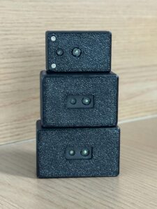
The DTOF Solid State LiDAR HM-LD1 is a compact SPAD dToF solid-state LiDAR module designed for real-time depth sensing and 3D point-cloud output. It is well suited for UAV perception, obstacle avoidance, altitude hold, terrain following, distance detection, autonomous navigation, smart inspection, robotic vision development, and embedded depth-sensing projects. It should be positioned as a lightweight UAV and robotics perception module, not as a complete survey-grade mapping payload by itself.
The module offers indoor ranging from 0.5 to 25 m and outdoor ranging from 0.2 to 8 m. Its ranging accuracy is ±3 cm, with a 60° horizontal by 45° vertical field of view. The product details specify 40 × 30 resolution, 10 fps frame rate, UART/UDP/UVC interfaces, -20 ℃ to 60 ℃ operating temperature, and 1.2 W power consumption. At only 28 g, it is practical for small drones where weight affects flight time and payload design.
HM-LD1 provides real-time depth images and 3D point-cloud data for environmental perception. This makes it useful for UAV altitude hold, terrain following, obstacle avoidance, inspection standoff control, robot navigation, SLAM experimentation, user presence detection, object recognition, volume measurement, and zone intrusion monitoring. The module supports SDKs for x86 Windows, x86 Linux, and ARM Linux, enabling development across PCs, Raspberry Pi, embedded Linux computers, and other compatible platforms.
Learn more or request integration support for the DTOF Solid State LiDAR HM-LD1.
Download the DTOF SSL HM-LD1 Product Brochure
| DTOF Solid State LiDAR HM-LD1 Specifications | |
|---|---|
| Product Name | DTOF Solid State LiDAR HM-LD1 |
| Product URL | https://myrobotproject.com/product/dtof-solid-state-lidar-hm-ld1/ |
| Dimension | 43.5 mm × 30 mm × 26.5 mm |
| Ranging Capability | Indoor: 0.5–25 m; Outdoor: 0.2–8 m |
| Ranging Accuracy | ±3 cm |
| Field of View | 60° horizontal × 45° vertical |
| Weight | 28 g |
| Resolution | 40 × 30 |
| Frame Rate | 10 fps |
| Interface | UART / UDP / UVC |
| Operating Temperature | -20 ℃ to 60 ℃ |
| Power Consumption | 1.2 W |
| Technology | SPAD dToF solid-state LiDAR |
| Output Data | Real-time depth images and 3D point cloud data |
| Supported Development Platforms | SDKs for x86 Windows, x86 Linux, and ARM Linux |
| Typical Applications | UAV obstacle avoidance, altitude hold, terrain following, distance detection, autonomous navigation, smart inspection, robotic vision development |
The HM-LD1 is especially attractive for development teams that need real-time 3D sensing in a compact package. The UART, UDP, and UVC interface options allow engineers to choose a data path that matches their controller, embedded computer, or PC-based test environment. The available SDKs for x86 Windows, x86 Linux, and ARM Linux reduce integration effort for prototyping and deployment.
For UAV work, the big win is balance. The module is light enough for small aircraft, low-power enough for embedded systems, and flexible enough for multiple software workflows. That does not mean it replaces a professional survey payload. It means it gives drone builders a practical depth-sensing module for perception, navigation development, and inspection support.
View Product Details & Pricing ➔
Industrial Applications for LiDAR with Drone Systems
UAV Obstacle Avoidance
Forward-facing LiDAR can help drones detect objects in the flight path. A depth map can be divided into warning zones, and the control system can slow down, stop, change direction, or alert the operator when an object is too close. This is best suited for low-to-moderate speed UAVs when the sensor range, frame rate, and processing latency are matched to the aircraft’s motion. A compact depth LiDAR is not a substitute for complete certified detect-and-avoid systems, but it can be a valuable perception layer for development and controlled applications.
Altitude Hold and Terrain Following
Downward-facing LiDAR can measure ground distance directly. This can provide more local altitude awareness than a barometer alone, especially at low altitude. For terrain following, the UAV can use LiDAR distance measurements to maintain a target height above the ground or surface. A depth LiDAR may also provide information about slopes, steps, and irregular surfaces within its field of view.
Infrastructure Inspection
LiDAR can support inspection of bridges, dams, expressways, industrial facilities, towers, and other structures by helping the drone maintain a safe distance from surfaces. The HM-LD1 product details specifically note usefulness for measuring distances to objects that are difficult for people to approach, such as bridges, expressways, and dams. For inspection missions, LiDAR can complement cameras by providing distance information while the camera captures visual evidence.
In real inspection work, standoff distance matters. Too far away and the camera may not capture enough detail. Too close and the aircraft risks striking the asset, especially in wind or turbulent air near structures. LiDAR gives the control system or pilot another measurement to work with.
Indoor UAV Navigation
Indoor UAVs often operate in GPS-denied environments such as warehouses, tunnels, industrial halls, and laboratories. LiDAR can help provide local depth perception for obstacle detection and navigation research. When combined with onboard computing and algorithms, depth data can support SLAM experimentation, wall following, object avoidance, and indoor autonomy development.
Robotics and Drone Development Platforms
Development teams often need sensors that work with Raspberry Pi, Jetson, Linux computers, Windows PCs, ARM Linux platforms, ROS, OpenCV, and custom embedded applications. HM-LD1 supports SDKs for x86 Windows, x86 Linux, and ARM Linux, making it useful for rapid prototyping and system integration. For a dedicated product-level overview, read HM-LD1: The Reliable dToF Solid-State LiDAR.

Buying Checklist for UAV LiDAR Selection
Use the following checklist before choosing a LiDAR for a drone project. The best sensor is not always the longest-range or highest-density unit. The best sensor is the one that fits the mission, aircraft, software architecture, and safety requirements.
- ✅ Mission: Mapping, inspection, obstacle avoidance, altitude hold, terrain following, or development?
- ✅ Weight: Can the UAV carry the sensor without unacceptable flight-time loss?
- ✅ Power: Does the power consumption fit the onboard battery and regulator design?
- ✅ Range: Is the indoor and outdoor detection distance suitable?
- ✅ Accuracy: Is the distance accuracy enough for the control algorithm?
- ✅ FOV: Does the field of view cover the required detection zone?
- ✅ Resolution: Do you need a single distance value or a depth image?
- ✅ Frame Rate: Is the update rate fast enough for the drone’s speed?
- ✅ Interface: Does the LiDAR support UART, UDP, UVC, or other required protocols?
- ✅ Software: Are SDKs, demos, or development resources available?
- ✅ Environment: Will it operate in the required temperature and lighting conditions?
- ✅ System Role: Is the LiDAR used for perception only, or does it need survey-grade georeferencing?
If your UAV project requires a compact depth LiDAR with low weight, low power consumption, and flexible interfaces, evaluate the DTOF Solid State LiDAR HM-LD1.
View Product Details & Pricing ➔
FAQ: LiDAR with Drone
Is there LiDAR for small drones or beginner UAV projects?
Can I use LiDAR with drone systems for budget land surveying?
How hard is it to integrate LiDAR with drones, flight controllers, or onboard computers?
What is the best type of LiDAR for drone obstacle avoidance?
Is drone LiDAR better than a camera for navigation?
How much range does a drone LiDAR need?
Can drone LiDAR work outdoors in sunlight?
Does LiDAR with drone require RTK?
Can I connect a LiDAR sensor directly to a flight controller?
What field of view is useful for UAV obstacle detection?
What is the difference between a depth map and a point cloud?
How does LiDAR help with drone terrain following?
What should I test before flying a drone with LiDAR?
View Product Details & Pricing ➔
📚 References & Further Reading
- Industry Standard: Blickfeld
- Related Guide: What Is RTK? The Centimeter-Level GPS Navigation Guide
- Related Guide: HM-D20 RTK Module
- Related Guide: HM-LD1: The Reliable dToF Solid-State LiDAR
- Product Page: DTOF Solid State LiDAR HM-LD1