


Here’s the deal: for robots, UAVs, autonomous vehicles, and survey systems, standard GPS usually is not tight enough. A normal consumer GPS receiver may put a machine within several meters of its real position. That is fine when a phone is helping somebody find a restaurant, but it is not fine for autonomous driving, drone mapping, construction staking, precision agriculture, robotic docking, or repeatable path tracking. In the shop and out in the field, a few meters of error can turn into survey rework, unstable flight paths, navigation drift, crop damage, or machine behavior nobody wants standing nearby. That is why rtk gps has become a core positioning technology for industrial automation: it uses real-time correction data to reduce satellite positioning errors and help systems reach centimeter-level accuracy where the work actually happens.
Look, choosing a cost-effective RTK GPS module is not just a matter of grabbing the cheapest board or the biggest accuracy claim on a datasheet. Engineers need to look at frequency bands, supported satellite constellations, RTK correction protocols, antenna integration, UART compatibility, environmental protection, timing performance, software support, and mechanical installation constraints. This guide walks through how RTK GPS works, how to compare modules for robotics, UAVs, and surveying, and how integrated options such as the Helical Antenna RTK Module HM-D20 and Multiband RTK Survey Module HM-D13 can cut integration effort while still delivering real centimeter-level performance.
One thing experienced field teams learn quickly is that positioning is a system problem, not just a receiver problem. A good RTK GPS module can still perform poorly if the antenna is mounted in the wrong spot, correction data is delayed, the UART wiring is noisy, or the software ignores fix status. The right hardware matters, but so does the whole chain from satellites to corrections to the controller that makes decisions.
For robotics, UAV, and survey projects, the best module is usually the one that gives the engineering team fewer surprises. Compact integrated modules are attractive because they reduce cabling, simplify antenna matching, and shorten the path from prototype to field test. Larger survey-style modules make sense when base-rover workflows, outdoor stability, and reliable signal reception are higher priorities than size.
Table of Contents
- 👉 What Is RTK GPS?
- 👉 How RTK GPS Works
- 👉 RTK GPS vs Standard GPS vs Static GPS Survey
- 👉 Key Buying Criteria for RTK GPS Modules
- 👉 RTK GPS Use Cases in Robotics, UAVs, and Surveying
- 👉 Recommended RTK GPS Modules and Real Specs
- 👉 Integration Guide: UART, NMEA, RTCM, ROS, and PX4
- 👉 How to Choose a Cost-Effective RTK GPS Module
- 👉 Installation and Field Performance Best Practices
- 👉 RTK GPS FAQ
- 👉 Choose the Right RTK GPS Module for Your Platform
What Is RTK GPS?
RTK GPS Definition for Industrial Users
RTK GPS, more accurately called RTK GNSS in most modern industrial applications, is a real-time positioning technique that improves satellite navigation accuracy by using correction data. RTK stands for Real-Time Kinematic. Instead of relying only on raw satellite signals received by a moving device, an RTK system compares satellite measurements from a known base station or correction network with measurements at the rover. The rover then applies correction information in real time to reduce major error sources such as atmospheric delay, satellite clock error, orbital error, and signal measurement uncertainty.
Many users still search for “RTK GPS” because GPS is the term everybody knows. In practice, professional RTK GPS modules usually receive signals from multiple GNSS constellations, not GPS alone. That matters because a robot, drone, survey rover, or autonomous vehicle may need to hold an accurate fix while moving through areas with partial sky blockage, vibration, changing orientation, or long operating hours. Multi-constellation reception gives the receiver more satellites to work with, which improves reliability and can help the system recover a high-accuracy RTK fix faster after temporary signal obstruction.
Why “GPS” Usually Means Multi-Constellation GNSS
Modern RTK GPS modules commonly support GPS, BeiDou, GLONASS, Galileo, QZSS, and IRNSS. That broader satellite access improves availability, positioning geometry, and field robustness. For example, the HM-D20 supports GPS L1/L5, BeiDou B1/B2A/B2I, GLONASS G1, Galileo E1/E5, QZSS L1/L5, and IRNSS L5. The HM-D13 supports GPS L1/L5, BeiDou B1/B2A/B2I, Galileo E1/E5, QZSS L1/L5, GLONASS G1, and IRNSS. For compact UAV and robotics builds, the Helical Antenna RTK Module HM-D20 is a practical example of an integrated RTK GPS module with built-in antenna and receiver, reducing the need for a separate GNSS antenna and RF cable.
In plain terms, GNSS diversity gives the receiver more chances to build a strong position solution. A machine working near trees, warehouses, cranes, vehicles, or industrial equipment may lose sight of some satellites at any given moment. If the receiver can track multiple constellations and multiple bands, it has more measurement data available and a better chance of maintaining a useful solution during real work.
How RTK GPS Works
Base Station, Rover, and Correction Data
An RTK GPS system normally includes a base station, a rover, and a correction data link. The base station is installed at a known coordinate or fixed reference point. The rover is the moving receiver mounted on a drone, robot, survey pole, unmanned ground vehicle, marine platform, agricultural machine, or autonomous vehicle. Both receivers observe satellite signals, but the base station can compare what it measures against its known position. From that comparison, it creates correction information that is transmitted to the rover.
The rover does not simply “receive GPS” the way a consumer navigation device does. It receives satellite measurements, receives correction data, and computes a corrected position solution. Correction data may come from a local base station, network RTK service, radio link, 4G communication path, or another system-level communication channel. The quality and continuity of this correction link directly affect RTK performance. A high-quality receiver cannot maintain RTK Fixed status if correction messages are delayed, interrupted, or incompatible.
In the field, this is where many projects either get solid or get frustrating. The receiver may be excellent, but if the correction stream drops every few seconds, the rover may bounce between Fixed, Float, and Single. That can cause a drone mission to lose mapping consistency, a robot to drift from its intended path, or a survey crew to waste time waiting for stable measurements.
RTCM Input and NMEA Output
Two protocol terms are especially important for integrators: RTCM and NMEA. RTCM is commonly used for correction data. It allows the rover to receive real-time correction messages from the base station or correction network. NMEA 0183 is a widely used output format for navigation data, including latitude, longitude, altitude, time, fix status, speed, and related positioning values. Flight controllers, embedded computers, mapping systems, survey controllers, and robotics software often rely on NMEA data because it is standardized and straightforward to parse.
The HM-D20 supports NMEA 0183 output and RTCM input at the rover side. The HM-D13 supports NMEA 0183 output and RTCM input at the rover side, and it also supports RTCM output at the base side. That distinction matters for teams building their own base-rover workflow, because base-side RTCM output can simplify the correction architecture in field surveying, construction mapping, and multi-device positioning deployments.
For a practical build, engineers should confirm the whole data path before final installation. The receiver needs the right baud rate, the controller needs the right input parser, the correction source needs the right RTCM message set, and the system software needs to use fix status correctly. If the controller treats Float or Single the same as Fixed, the rest of the machine may make decisions based on lower-quality data.
Fixed RTK, Float RTK, and Accuracy Expectations
RTK position quality is often described using states such as Single, Float, and Fixed. Single means the receiver is operating without RTK correction and typically provides meter-level positioning. RTK Float means correction data is available, but the receiver has not fully resolved carrier-phase ambiguity. RTK Fixed means ambiguity has been resolved, and the system can deliver its best centimeter-level positioning. Datasheet accuracy such as H: 1 cm + 1 ppm and V: 1.5 cm + 1 ppm assumes suitable field conditions, good satellite visibility, stable corrections, appropriate antenna placement, and correct configuration.
In modern autonomy stacks, RTK GPS is often combined with perception sensors from suppliers such as Luminar Technologies or industrial sensing platforms from SICK. RTK provides absolute outdoor positioning, while LiDAR, cameras, radar, IMU, wheel odometry, and safety sensors contribute local awareness, obstacle detection, and motion estimation.
That combination is important. RTK GPS tells the machine where it is in global coordinates, but it does not tell the machine that a pallet, person, fence post, vehicle, or tree branch is in the way. Good autonomy uses RTK as one strong layer in a larger positioning and perception system.
RTK GPS vs Standard GPS vs Static GPS Survey
Standard GPS
Standard GPS is suitable for consumer navigation, fleet tracking, asset location, outdoor recreation, and general-purpose positioning. It normally provides meter-level accuracy, which is enough for showing a car on a road or locating a vehicle inside a yard. For industrial machines, however, meter-level accuracy can be insufficient. A drone mapping project may need accurate image geotagging. A robot may need to follow a defined route with repeatability. A survey rover may need to record points with centimeter-level confidence. In those cases, standard GPS cannot provide the positioning reliability or precision required for professional workflows.
Here’s a simple way to think about it: standard GPS is good for knowing which road or field you are in, while RTK GPS is used when the exact lane, row, pass, boundary, or point matters. That difference is not academic. It affects whether a machine lines up correctly, whether a map overlays cleanly, and whether a survey point can be trusted.
RTK GPS
RTK GPS provides corrected positioning in real time. It is widely used for UAV mapping, robotic navigation, construction layout, agricultural guidance, autonomous vehicles, marine positioning, industrial inspection robots, and survey field work. The main advantage is that it delivers accurate position output while the system is moving. This makes RTK practical for active field operations where a user or machine must make decisions immediately, not after post-processing.
RTK is especially useful when the machine must repeat the same route or return to the same location many times. That is common in inspection, mowing, spraying, construction layout, mapping corridors, port automation, and mobile robotics. Repeatability is often just as valuable as raw accuracy because the system needs predictable behavior across shifts, jobs, and operators.
Static GPS Survey
Static GPS survey is a different workflow. It typically relies on longer observation periods and post-processing to calculate high-accuracy coordinates. Static surveying is valuable for control points, geodetic survey, and reference station establishment, but it is slower and less suitable for mobile autonomy. RTK is preferred when a drone, robot, vehicle, or surveyor needs live positioning output in the field.
| Positioning Method | Typical Accuracy | Real-Time Output | Best Use Cases |
|---|---|---|---|
| Standard GPS | Meter-level | Yes | Navigation, tracking, basic positioning |
| RTK GPS | Centimeter-level | Yes | Robotics, UAVs, surveying, autonomous systems |
| Static GPS Survey | High accuracy after processing | No, typically post-processed | Control points, geodetic survey, reference stations |
✅ Use standard GPS when rough location is enough and the system can tolerate several meters of error. ✅ Use RTK GPS when the machine needs live centimeter-level positioning while moving. ✅ Use static GPS survey when the job allows longer observations and post-processing for control or geodetic work.
Key Buying Criteria for RTK GPS Modules
Multi-Band GNSS Support
Multi-band GNSS support is one of the most important technical criteria when evaluating an RTK GPS module. L1-only receivers can work in many conditions, but multi-band receivers that support L1 and L5 or equivalent bands can improve ionospheric error mitigation, ambiguity resolution, and RTK fix stability. In practical terms, multi-band reception helps the system maintain reliable positioning when the environment is less than perfect. This is especially useful for drones, mobile robots, survey rovers, agricultural machines, and marine platforms that operate for long periods under changing sky conditions.
Look for support across GPS, BeiDou, Galileo, GLONASS, QZSS, and IRNSS when your project requires robust field performance. The HM-D20 and HM-D13 both provide broad multi-constellation support, making them suitable for applications where satellite availability and correction reliability are critical.
In the shop, it is easy to test a receiver under clean open sky and assume the job is done. Real sites are messier. Buildings reflect signals, trees block satellites, machines vibrate, and operators do not always park equipment in perfect conditions. Multi-band and multi-constellation support gives the system more margin when conditions get ugly.
RTK Accuracy Specification
Accuracy specifications should be read carefully. The value H: 1 cm + 1 ppm means horizontal accuracy is expressed as a base centimeter value plus a baseline-related component. The value V: 1.5 cm + 1 ppm means vertical accuracy is expressed similarly, but vertical positioning is typically more challenging than horizontal positioning. The “ppm” component means parts per million and is usually related to baseline distance from the correction source. A longer baseline between the rover and correction source can increase expected error. This is why a strong receiver must be paired with a suitable correction strategy and field validation process.
Do not treat the accuracy line as a guarantee under all conditions. That number assumes the receiver has the satellite geometry, signal quality, correction input, and installation quality it needs. If the antenna is tucked under a metal cover or the RTCM stream is unreliable, the receiver cannot magically produce survey-grade output.
Integrated Antenna vs External Antenna
Integrated antenna modules combine the receiver and GNSS antenna in one mechanical package. This approach reduces RF cable complexity, lowers the risk of antenna mismatch, simplifies installation, and can make the final design cleaner. It is especially attractive for UAVs, mobile robots, unmanned vehicles, and compact outdoor devices. External antenna systems can still be useful when a vehicle requires flexible antenna placement, larger ground planes, or specialized mounting. However, they require more attention to cable routing, connector quality, RF loss, waterproofing, and mechanical strain relief.
The HM-D20 uses a compact helical antenna design and includes a built-in GNSS module and antenna. The HM-D13 uses a mushroom-shaped integrated GNSS antenna. Both approaches reduce installation complexity compared with separate receiver-and-antenna systems.
✅ Integrated modules reduce part count. ✅ They also reduce RF cabling mistakes. ✅ They make field replacement simpler. ⚙️ External antennas still make sense when the vehicle body forces the receiver electronics and antenna to be placed in different locations.
Interface and Protocol Compatibility
Industrial RTK GPS integration depends heavily on interface compatibility. A module may have excellent positioning performance, but it must also communicate cleanly with the target controller. HM-D20 and HM-D13 both use a TTL-level UART interface and 115200 bps baud rate. They support NMEA 0183 output and RTCM correction input at the rover side. HM-D13 additionally supports RTCM output at the base side. For robotics and UAV projects, teams should also confirm software support for ROS, Python, C++, PX4, or their own embedded parsing pipeline.
This is a common place for avoidable trouble. TTL UART is not RS232. TX and RX need to be crossed correctly. Ground needs to be shared. Baud rate must match. The controller must be configured to read the right messages. A bad electrical connection can look like a GNSS problem, even when the receiver itself is working fine.
Environmental Protection and Timing
Outdoor positioning modules must survive temperature swings, rain, dust, vibration, and long deployment cycles. HM-D20 is specified with IP67 waterproof protection and an operating temperature of -40 ℃ to 85 ℃. HM-D13 is specified with an operating temperature of -40 ℃ to 85 ℃ and uses outdoor UV-resistant PC material described as windproof and rainproof. Timing synchronization accuracy can also matter in robotics, mapping payloads, sensor fusion, and synchronized acquisition systems. Both supplied product datasets list 20 ns timing synchronization accuracy.
For field machines, environmental protection is not a nice extra. It affects uptime. A module installed on a drone, rover, survey pole, marine platform, or farm machine may see rain, dust, vibration, heat soak, freezing mornings, and rough handling. The mechanical package should fit the job, not just the electrical schematic.
RTK GPS Use Cases in Robotics, UAVs, and Surveying
Robotics and Autonomous Vehicles
Outdoor robots need absolute positioning that does not drift over long travel distances. Wheel odometry and inertial sensors are useful for short-term motion estimation, but they accumulate error over time. LiDAR and visual odometry can improve local positioning, but they may depend on recognizable features, lighting, maps, or environmental structure. RTK GPS provides a global outdoor position reference, helping robots follow planned paths, return to known locations, align with rows or lanes, and maintain repeatability across missions.
Applications include delivery robots, lawn-mowing robots, autonomous inspection vehicles, port automation systems, logistics yard vehicles, UGVs, smart tractors, and industrial mobile platforms. In many professional systems, RTK GPS is fused with IMU, odometry, LiDAR, camera perception, and map matching. Perception sensors and industrial safety platforms from companies such as Luminar Technologies and SICK are often part of broader autonomy ecosystems, while RTK GPS provides the absolute positioning layer required for outdoor navigation.
For robots, the practical value is repeatable behavior. A robot that is supposed to run the same inspection route, mow the same boundaries, align to rows, or dock at a fixed point needs location data it can trust across time. RTK GPS gives that system a stable outdoor reference, while the rest of the sensor stack handles local movement and obstacle awareness.
UAV Mapping and Drone Navigation
RTK GPS is valuable for UAVs because drones often need accurate flight paths, repeatable routes, and precise location tagging. In photogrammetry and LiDAR mapping, RTK can reduce dependence on ground control points and improve georeferencing consistency. In agriculture, RTK helps drones fly precise survey lines across fields. In infrastructure inspection, it improves repeatability when returning to the same asset or inspection corridor. For autonomous UAV missions, stable positioning also supports safer navigation and better mission execution.
The supplied FAQ information states that the HM-D20 can connect to the GPS1 or GPS2 port on a Pixhawk flight controller, with a GPS1 communication cable provided. Users then complete parameter configuration according to the user guide. Before flight, operators should confirm satellite reception, correction status, RTK fix state, and flight-controller GPS health in ground control software.
⚙️ For UAV work, verify the module is mounted with a clear sky view. ⚙️ Keep it away from high-current power wiring and major RF noise sources where possible. ⚙️ Confirm RTK Fixed status before missions that depend on centimeter-level positioning. ⚙️ Log flight data during early tests so position quality can be reviewed after the flight.
Surveying, Construction, Marine, and Agriculture
Surveying and construction teams use RTK GPS for topographic mapping, construction site layout, boundary work support, earthwork monitoring, machine guidance, and control point collection. The HM-D13 is especially relevant for survey-oriented workflows because it uses a larger integrated mushroom antenna, supports multiband GNSS, and provides RTCM output at the base side. Marine and industrial users can apply RTK GPS to unmanned surface vehicles, harbor automation, container yard positioning, mining operations, quarry logistics, and precision agriculture guidance. In each case, the value of RTK is not only its accuracy but also its ability to deliver that accuracy in real time.
On construction and survey jobs, time matters. Crews do not want to fight equipment or repeat measurements because the rover could not hold a stable correction. A module that supports the right correction workflow, has a practical outdoor housing, and fits the way crews actually work can save more money than a cheaper receiver that creates downtime.
Recommended RTK GPS Modules and Real Specs
The two modules below are designed for cost-effective centimeter-level positioning, but they serve different integration needs. HM-D20 is compact, rugged, waterproof, and suitable for UAVs, robots, unmanned vehicles, ships, and compact positioning systems. HM-D13 is a larger multiband RTK survey module with an integrated mushroom antenna, strong outdoor performance, and optional 4G radio module support. Both modules support multi-constellation GNSS, centimeter-level RTK positioning, TTL UART communication, and 115200 bps baud rate.
Here’s the practical split: HM-D20 is the compact rugged option when space and simple integration matter. HM-D13 is the survey-style option when a larger antenna package, base-side RTCM output, and professional outdoor workflow matter more than compact size.
Helical Antenna RTK Module HM-D20

The HM-D20 is an integrated GNSS receiver and helical antenna RTK module designed for compact platforms. Its built-in GNSS module and antenna allow users to deploy the device without an external antenna, reducing wiring complexity and simplifying installation. The module supports GPS L1/L5, BeiDou B1/B2A/B2I, GLONASS G1, Galileo E1/E5, QZSS L1/L5, and IRNSS L5. It provides RTK position accuracy of H: 1 cm + 1 ppm and V: 1.5 cm + 1 ppm under appropriate RTK conditions. It outputs NMEA 0183 and accepts RTCM input at the rover side through a TTL-level UART interface at 115200 bps.
With dimensions of Φ44 × 37 mm, IP67 waterproof protection, -40 ℃ to 85 ℃ operating temperature, 20 ns timing synchronization accuracy, and an L1/L5 GNSS antenna system listed as at least 40 dB high gain, the HM-D20 is well suited for UAVs, robots, unmanned vehicles, ships, and other positioning systems where compact size and rugged outdoor operation matter.
Multiband RTK Survey Module HM-D13
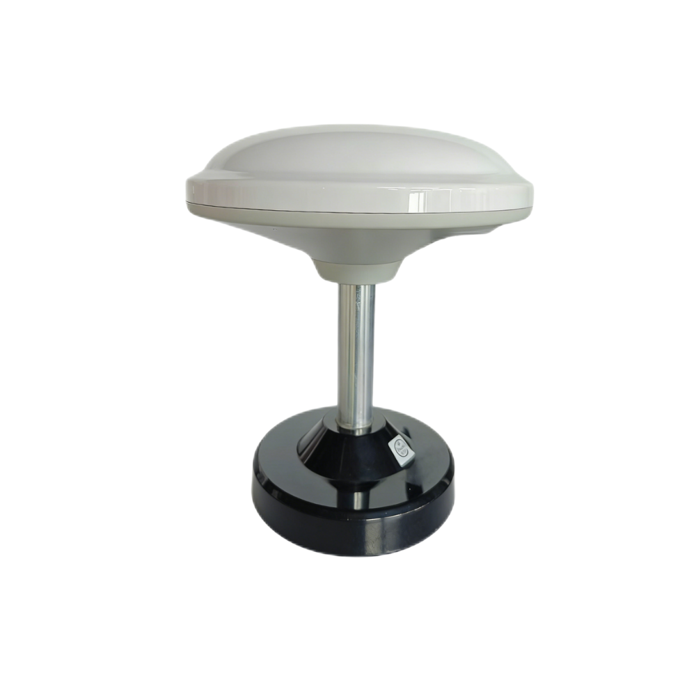
The HM-D13 is a multiband RTK survey module with an integrated mushroom-shaped GNSS antenna. It is designed for stable signal reception, centimeter-accurate positioning, and outdoor survey-style deployment. The module supports GPS L1/L5, BeiDou B1/B2A/B2I, Galileo E1/E5, QZSS L1/L5, GLONASS G1, and IRNSS. It provides RTK position accuracy of H: 1 cm + 1 ppm and V: 1.5 cm + 1 ppm. It supports NMEA 0183 output and RTCM input at the rover side, plus RTCM output at the base side, making it suitable for base-rover workflows.
The HM-D13 uses a TTL-level UART interface at 115200 bps, provides 20 ns timing synchronization accuracy, operates from -40 ℃ to 85 ℃, and weighs less than 550 g. Its dimensions are Φ152 × 67.9 mm. The supplied product details describe UV-resistant PC material, windproof and rainproof outdoor performance, and optional 4G radio module support. These characteristics make it a strong choice for surveying, mapping, UAV missions, construction sites, and outdoor robotics.
| Specification | Helical Antenna RTK Module HM-D20 | Multiband RTK Survey Module HM-D13 |
|---|---|---|
| Recommended Applications | UAVs, robots, unmanned vehicles, ships, compact positioning systems | Surveying, mapping, UAV missions, construction sites, outdoor robotics |
| Frequency Band | GPS L1/L5, BeiDou B1/B2A/B2I, GLONASS G1, Galileo E1/E5, QZSS L1/L5, IRNSS L5 | GPS L1/L5, BeiDou B1/B2A/B2I, Galileo E1/E5, QZSS L1/L5, GLONASS G1, IRNSS |
| RTK Position Accuracy | H: 1 cm + 1 ppm, V: 1.5 cm + 1 ppm | H: 1 cm + 1 ppm, V: 1.5 cm + 1 ppm |
| Protocol | NMEA 0183 output and RTCM input at rover side | NMEA 0183 output and RTCM input at rover side; RTCM output at base side |
| Baud Rate | 115200 bps | 115200 bps |
| Interface | TTL level UART interface | TTL level UART interface |
| Timing Synchronization Accuracy | 20 ns | 20 ns |
| Antenna Design | Integrated helical GNSS antenna system, at least 40 dB high gain | Integrated mushroom-shaped GNSS antenna |
| Dimensions | Φ44 × 37 mm | Φ152 × 67.9 mm |
| Weight | Not specified in supplied data | <550 g |
| Operating Temperature | -40 ℃ to 85 ℃ | -40 ℃ to 85 ℃ |
| Waterproof / Outdoor Protection | IP67 waterproof rugged housing | Outdoor UV-resistant PC material; windproof and rainproof design described in product details |
| Optional Communication | Not specified in supplied data | Supports optional 4G radio module |
| Product Link | HM-D20 RTK Module | HM-D13 RTK Survey Module |
Choose HM-D20 when the priority is compact size, rugged waterproof design, helical antenna integration, and simple installation on UAVs, robots, unmanned vehicles, or marine platforms. Choose HM-D13 when the application benefits from a larger survey-style integrated antenna, base-side RTCM output, optional 4G radio module support, and a form factor designed for professional outdoor survey and mapping workflows.
✅ HM-D20 is the better fit when the module needs to sit on a compact vehicle and survive outdoor use without adding external antenna complexity. ✅ HM-D13 is the better fit when the job leans toward survey, mapping, construction, or base-rover correction workflows. ⚙️ Both still need proper mounting, correction input, power quality, and software configuration to deliver their best performance.
Integration Guide: UART, NMEA, RTCM, ROS, and PX4
UART Electrical Interface
UART integration looks simple, but field reliability depends on correct electrical and wiring practices. HM-D20 and HM-D13 use TTL-level UART interfaces, so engineers should confirm voltage compatibility before connecting the module to a flight controller, embedded computer, robot controller, or survey device. TTL UART should not be confused with RS232 electrical signaling. TX and RX must be crossed correctly, the system must share a common ground, and the baud rate should be configured to 115200 bps unless the user guide specifies a different project setting.
For UAV and robotics platforms, cable routing is also important. Keep signal wiring away from high-current motor lines, switching regulators, ESCs, and high-power radio transmitters where possible. Poor wiring can create intermittent communication errors that look like GNSS performance problems but are actually electrical integration problems.
⚙️ Confirm UART voltage before connecting hardware. ⚙️ Cross TX and RX correctly. ⚙️ Share ground between the module and controller. ⚙️ Set the baud rate to 115200 bps when using the supplied default configuration. ⚙️ Verify live NMEA output before locking down the enclosure.
NMEA Data Parsing
NMEA output provides the navigation data needed by many controllers and software systems. Typical data includes latitude, longitude, altitude, fix status, satellite count, time, and dilution-of-precision values where available. The supplied HM-D20 FAQ states that positioning data can be integrated into a software system through a serial interface and that ROS, Python, and C++ demos are available. This is useful for teams building custom software because the RTK GPS module can feed a localization pipeline, mapping payload, autonomous navigation stack, or industrial data logging system.
When writing software, do not parse only latitude and longitude and call the job done. A proper integration should pay attention to fix type, timing, update rate, coordinate frame, antenna offset, and data freshness. The controller needs to know not only where the module says it is, but how trustworthy that position is at that moment.
RTCM Correction Input
RTCM is the correction data path that enables the rover to calculate an RTK solution. A base station or network sends RTCM messages, the rover receives them, and the rover computes a corrected position solution. If RTCM is missing, delayed, or incompatible, the receiver may remain in Single or Float mode rather than RTK Fixed. HM-D13 adds a useful base-rover feature by supporting RTCM output at the base side, which can help teams build their own correction system for surveying and field mapping.
For production systems, correction reliability should be tested under load and during motion. A correction link that works on a bench may not behave the same way when a vehicle is moving across a jobsite, a drone is flying at distance, or a survey team is operating near buildings and equipment. Watch correction age, fix state, and dropouts during real operation.
PX4 and Pixhawk Integration
For PX4 or Pixhawk integration, the supplied product FAQ states that the HM-D20 can be connected to GPS1 or GPS2 on the Pixhawk flight controller, with a GPS1 communication cable provided. After wiring, users should follow the user guide to complete parameter configuration. Before flight, confirm GPS status, correction status, fix type, satellite count, and communication health in the ground control software. RTK should be validated on the ground before any mission that depends on centimeter-level positioning.
Look, a first flight is not the place to discover a wiring, configuration, or correction problem. Validate the receiver on the ground, verify that the flight controller sees the expected GPS status, and confirm the RTK state before takeoff. For mapping and inspection missions, logging this data is useful because it gives the team evidence of position quality after the mission.
How to Choose a Cost-Effective RTK GPS Module
Do Not Buy by Accuracy Alone
Two RTK GPS modules can list similar accuracy while performing differently in real systems. Antenna design, multi-band support, constellation coverage, correction stability, housing quality, cable design, timing behavior, and technical support all affect total value. A low-cost receiver that requires extra antennas, custom cabling, repeated troubleshooting, or frequent field repair may cost more in the long run than an integrated module that installs quickly and works reliably.
In industrial work, the cheapest part on the purchase order is not always the cheapest part in the final machine. If the module burns engineering time, creates field failures, needs special cabling, or makes support harder, the total cost goes up. Cost-effective means the module helps the system get built, tested, shipped, and maintained without unnecessary pain.
Match the Form Factor to the Platform
For small drones, compact robots, unmanned vehicles, and space-constrained platforms, HM-D20 is a practical fit because it combines a helical GNSS antenna, receiver, IP67 protection, and compact dimensions of Φ44 × 37 mm. For survey poles, construction site mapping, base-rover workflows, and outdoor professional surveying, HM-D13 is often the better choice because it provides a larger mushroom-shaped integrated antenna, survey-oriented form factor, and RTCM output at the base side.
Mechanical fit matters as much as electrical fit. A module that is too large for a drone may force a poor mounting location. A tiny module may not be the best fit for a survey workflow that benefits from a larger antenna package and outdoor handling. Match the module to the machine, not the other way around.
Evaluate Total Integration Cost
Cost-effective selection should include module price, antenna cost, cabling, installation time, software integration, technical support, field failure risk, and supply stability. Integrated antenna RTK GPS modules can reduce RF cable loss, installation complexity, and mechanical uncertainty. Available software demos in ROS, Python, and C++ can reduce development time. Technical support and OEM/ODM customization can also matter for teams moving from prototype to production.
✅ Count antenna and cable cost, not just receiver cost. ✅ Count engineering time spent debugging wiring and protocols. ✅ Count the value of available demos and documentation. ✅ Count the cost of downtime if a field unit fails in rain, dust, vibration, or heat. ✅ Count how easy the module is to support once more units are deployed.
| Requirement | Recommended Priority | Suggested Module Fit |
|---|---|---|
| Compact UAV or robot installation | Small size, integrated antenna, rugged housing | HM-D20 |
| Professional surveying and mapping | Survey-style antenna, base/rover correction support | HM-D13 |
| Outdoor harsh environment | Wide temperature range and protection design | HM-D20 or HM-D13 depending on form factor |
| Base station correction output | RTCM output at base side | HM-D13 |
Use the table as a starting point, not a substitute for field testing. A module that looks right on paper should still be validated on the actual platform, with the actual correction source, under the actual operating conditions. That is how engineering teams catch mounting issues, communication problems, and correction dropouts before customers or operators find them.
Installation and Field Performance Best Practices
Antenna Placement
Antenna placement has a major effect on RTK GPS performance. Even the best module cannot deliver stable centimeter-level positioning if the antenna is blocked by metal, mounted near reflective surfaces, or placed close to strong RF interference. Install the module with a clear sky view, maintain stable orientation, avoid nearby obstructions, and use a secure mechanical mount that prevents vibration. For UAVs, position the module away from high-current power electronics where possible. For robots and vehicles, test several mounting locations before finalizing the enclosure or bracket design.
In the shop, it is tempting to mount the receiver wherever the bracket is convenient. In the field, that shortcut can cost accuracy. The antenna needs to see the sky, and it needs to be kept away from things that reflect, block, or interfere with GNSS signals. A good mechanical location is part of the positioning system.
Correction Link Reliability
RTK Fixed status depends on reliable correction input. Engineers should verify base station distance, network RTK availability, radio or 4G reliability, correction latency, and RTCM message compatibility. Intermittent corrections can cause the rover to drop from Fixed to Float or Single mode. For applications such as drone mapping, construction layout, or autonomous navigation, correction reliability should be tested under real operating conditions, not only in a workshop or lab.
⚙️ Check correction age during operation. ⚙️ Confirm RTCM compatibility. ⚙️ Test radio or 4G coverage across the actual work area. ⚙️ Watch whether the receiver holds RTK Fixed while the machine is moving. ⚙️ Log enough data to diagnose dropouts instead of guessing after the fact.
Power, Grounding, and EMI
Stable power and clean grounding are essential. Voltage dips, ground loops, poor connectors, and EMI from motors or switching power supplies can cause communication failures or degraded receiver behavior. Route cables carefully, protect connectors from vibration and moisture, and keep UART lines away from high-current conductors. For production systems, validate performance across temperature, vibration, and power supply variation.
Many “GPS problems” turn out to be power, ground, or EMI problems. If the module resets, drops serial data, or behaves differently when motors start, do not blame satellites first. Check power quality, cable routing, connector strain relief, grounding, and shielding practices.
Field Validation Checklist
Before deployment, confirm satellite count, correction input, fix status, NMEA output, and software parsing. Test in open sky before testing near buildings, trees, cranes, or metal structures. Log data during motion, compare repeatability at known points, and verify that the target controller, ROS node, PX4 configuration, survey software, or embedded application receives the correct coordinates and fix status. Also confirm whether the reported position corresponds to the antenna phase center, because mechanical offsets may matter for mapping, robotics, and vehicle control.
✅ Verify open-sky operation first. ✅ Confirm RTK Fixed status before precision work. ✅ Test the actual installation, not just a loose bench setup. ✅ Compare known points or repeatable routes. ✅ Account for antenna offset if the machine uses the position for control, mapping, or alignment.
RTK GPS FAQ
What is RTK GPS and why is it more accurate than normal GPS?
What is the difference between static GPS survey and RTK survey?
What should I look for in a cost-effective RTK GPS module?
Can RTK GPS be used for autonomous robots?
Is RTK GPS suitable for UAVs and drones?
What is the difference between HM-D20 and HM-D13?
Do RTK GPS modules need an external antenna?
What protocols are important for RTK GPS integration?
How accurate are HM-D20 and HM-D13?
Can RTK GPS data be integrated into custom software?
Choose the Right RTK GPS Module for Your Platform
If your project requires centimeter-level positioning for UAVs, robots, autonomous vehicles, survey equipment, or outdoor industrial systems, the right RTK GPS module should match both your accuracy target and your integration environment. HM-D20 is designed for compact, rugged installation where an integrated helical antenna, IP67 protection, and simple UART communication are important. HM-D13 is better suited for survey-style workflows, construction mapping, and base-rover applications that benefit from a larger integrated antenna and base-side RTCM output.
For engineering teams, the best selection is usually the module that reduces total integration risk. Consider the complete system: satellite support, correction flow, antenna placement, UART wiring, protocol compatibility, operating temperature, outdoor protection, software parsing, and available support. A well-matched RTK GPS module can shorten development time, improve field reliability, and help your platform achieve repeatable centimeter-level positioning.
Here’s the deal: the right RTK GPS module is not the one with the prettiest datasheet. It is the one that fits the platform, holds a stable correction, communicates cleanly with the controller, survives the environment, and gives the team confidence during real field work. For compact robots and UAVs, HM-D20 is a strong practical choice. For survey, mapping, and base-rover field workflows, HM-D13 is often the better fit.
View HM-D20 RTK GPS Module
View HM-D13 RTK Survey Module
Download HM-D20 GNSS RTK Receiver Module Datasheet
📚 References & Further Reading
- Industry Standard: SICK industrial sensing and automation solutions
- Industry Standard: Luminar Technologies autonomy and perception systems
- Related Guide: Helical Antenna RTK Module HM-D20
- Related Guide: Multiband RTK Survey Module HM-D13
- Related Guide: GNSS RTK Receiver Module HM-D20 Datasheet Download






