


LiDAR Sensor Working Explained: How to Choose Reliable 3D Sensing for Robots and Drones
Here’s the deal: a robot or drone cannot avoid an obstacle just because a sensor reports that something is nearby. The machine needs to know how far away the object is, where it sits inside the sensor’s field of view, and whether that distance is changing fast enough to require braking, steering, climbing, hovering, or another control response. LiDAR provides that geometric information by sending out laser light, detecting the photons that return, and converting their travel time into distance. The basic equation is simple. Building a dependable 3D perception system is not. Optical design, detector sensitivity, ambient-light rejection, frame rate, field of view, target reflectivity, calibration, data transport, processing latency, and mounting geometry all affect what the vehicle can actually see.
This guide walks through LiDAR sensor working principles from the moment a pulse leaves the emitter to the point where software receives a depth map or point cloud. The focus is solid-state direct time-of-flight sensing for compact robots, drones, and autonomous equipment. It also covers the specifications that matter in the shop and in the field: indoor and outdoor range, accuracy, spatial resolution, sunlight performance, power consumption, weight, interfaces, temperature limits, and end-to-end latency. As a practical reference, the guide examines the compact HM-LD1-NV 3D dToF LiDAR, including its 40 x 30 depth resolution, 60° horizontal x 45° vertical field of view, 28 g weight, and specified outdoor ranging capability under 80 klux illumination.
Table of Contents
- 👉 What a LiDAR Sensor Measures
- 👉 How a LiDAR Sensor Works Step by Step
- 👉 Direct Time-of-Flight Distance Measurement
- 👉 How Solid-State 3D dToF LiDAR Works
- 👉 Depth Maps and Point Clouds
- 👉 Inside a LiDAR Sensor
- 👉 Factors That Affect LiDAR Performance
- 👉 How to Read LiDAR Specifications
- 👉 HM-LD1-NV Specifications
- 👉 Selecting LiDAR for Robots and Drones
- 👉 Integration and Validation Workflow
- 👉 Common LiDAR Failure Modes
- 👉 LiDAR Selection Checklist
- 👉 Frequently Asked Questions
- 👉 Conclusion and Product Evaluation
What a LiDAR Sensor Measures
LiDAR stands for light detection and ranging. At its core, a LiDAR sensor estimates the distance to a surface by transmitting controlled optical energy and detecting a portion of that energy after it reflects back. A single-point rangefinder reports one distance along one direction. A 3D LiDAR collects measurements across many directions or image positions, giving the control system a spatial description of the surfaces around it.
That distinction matters on a working machine. A basic proximity switch may tell a controller that an object entered a detection zone, but it usually cannot describe the object’s location, outline, or orientation. A 3D depth sensor supplies a field of measurements. From that field, perception software can estimate free space, obstacle boundaries, surface angles, and movement from one frame to the next.
Distance, Direction, and Measurement Confidence
Look at a useful LiDAR measurement as having three parts. First is range, meaning the estimated distance between the sensor and the reflecting surface. Second is direction or pixel position, which identifies the horizontal and vertical location tied to that range. Third is a quality value. Depending on the manufacturer, that value may be called amplitude, intensity, confidence, validity, or status. Quality data helps software tell the difference between a strong return and one that is weak, saturated, ambiguous, or invalid.
Not every LiDAR exposes all of those values through its public protocol. One product described as a 3D sensor may send only processed depth. Another may provide depth, confidence, amplitude, timestamps, calibration information, and diagnostic flags. Do not assume two sensors with similar range and resolution specifications deliver equivalent data. Read the protocol documentation and inspect the software development kit before committing the host design.
LiDAR Compared with Cameras, Ultrasonic Sensors, and Radar
RGB cameras are excellent for recording color, texture, labels, and appearance, but a conventional single camera does not directly measure metric depth. Depth has to be inferred through stereo geometry, motion, structured light, or learned monocular estimation. Ultrasonic sensors are inexpensive and useful for close-range detection, although their broad acoustic beams and relatively limited spatial detail can make it hard to separate nearby objects. Radar handles difficult lighting and many weather conditions well, but its angular resolution, near-field behavior, and integration requirements differ from optical ranging.
LiDAR measures optical range directly and can return useful geometry from a surface with very little visible texture. Still, it is not a universal replacement for every other sensor. In the shop, the strongest mobile systems usually combine LiDAR with cameras, inertial measurement units, wheel odometry, GNSS, ultrasonic sensing, or radar. That sensor fusion provides context and redundancy when one sensing method runs into glare, darkness, weak reflectivity, weather, vibration, or a blocked optical path.
How a LiDAR Sensor Works Step by Step
LiDAR sensor working is best understood as a repeating cycle: emit light, collect reflected photons, measure time, apply calibration, and reconstruct the scene. The sensor runs this cycle continuously and produces frames that navigation and control software can use.
1. The Emitter Produces Controlled Laser Light
A laser source generates a pulse or another controlled optical signal. The HM-LD1-NV uses a specified 940 nm vertical-cavity surface-emitting laser, usually shortened to VCSEL. That wavelength falls in the near-infrared region, so a person normally cannot see the emitted light.
Invisible does not automatically mean harmless. Eye safety depends on the complete optical system: output power, pulse duration, repetition rate, beam divergence, wavelength, accessible emission, and expected exposure all count. The HM-LD1-NV is specified as Class 1 eye safe, but it still needs to be installed and operated according to current manufacturer documentation. Adding lenses, covers, or reflective parts near the emitter can change optical behavior and deserves a proper engineering review.
2. Transmitter Optics Project the Light into the Scene
Optical components distribute the emitted light across a defined field of view. The method depends on the architecture. A scanning LiDAR can steer a narrow beam through a sequence of angles. Other systems illuminate a line or a broader area and use a detector array to associate the returned photons with different positions in the scene.
Here’s the practical tradeoff: field of view, range, spatial resolution, and signal strength are connected. Broad illumination covers more of the scene, but it also spreads available optical energy over a wider angular area. A large field-of-view number may look attractive on a data sheet, yet it must be judged as part of the whole transmitter, receiver, detector, and processing design.
3. Surfaces Reflect a Fraction of the Light
When the transmitted light reaches an object, part of the energy is absorbed, part may pass through the material, and part is reflected. Matte surfaces commonly scatter light in many directions, which allows a small fraction to return to the receiver. Dark or absorbent materials usually return less optical energy than bright surfaces.
Glass, polished metal, water, retroreflective tape, and sharply angled panels can behave very differently from a painted wall. A mirror-like surface may send most of the light away from the receiver. A retroreflector can send an unusually strong return directly back. That is why a maximum range measured against a large, bright, perpendicular target should never be treated as a guaranteed range against every real obstacle.
4. The Receiver Detects Returned Photons
Receiver optics collect a small portion of the reflected signal and focus it onto a photodetector. A single-photon avalanche diode, or SPAD, can register extremely weak optical returns. The hard part is separating likely signal photons from sunlight, optical crosstalk, detector noise, reflections inside the enclosure, and unrelated active light sources.
5. Timing Electronics Estimate Distance
In direct time-of-flight LiDAR, timing electronics estimate the interval between transmission and reception. The light travels from the sensor to the object and then back to the sensor, so the measured path is twice the one-way distance. Dividing the round-trip path by two gives the estimated range.
6. Processing Produces Spatial Output
Raw detector events generally should not go straight to a motor controller. Internal processing can apply timing correction, per-pixel calibration, background rejection, invalid-pixel handling, confidence scoring, and temporal filtering. The resulting depth frame can support obstacle detection, localization, mapping, landing assistance, occupancy monitoring, gesture processing, or privacy-conscious human sensing.
Direct Time-of-Flight Distance Measurement
The main direct time-of-flight relationship is:
distance = (speed of light × round-trip time) ÷ 2
d = cΔt ÷ 2
In that equation, d is the one-way distance to the target, c is the speed of light, and Δt is the measured time between transmission and reception. Light travels at approximately 299,792,458 meters per second in a vacuum and only slightly slower in air.
Consider a target five meters away. The light travels five meters out and five meters back, for a total path of ten meters. The ideal round-trip travel time is about 33.4 nanoseconds. That is a very short interval. Centimeter-scale ranging therefore demands precise timing electronics, stable calibration, and enough return signal to identify the correct event.
In a practical dToF sensor, the processor may combine many photon detections instead of trusting one event. It can build a timing histogram showing how often detections occur at different delay intervals. A concentration of detections at a repeatable delay is likely to represent the target. Detections scattered across other intervals are more likely to be background noise. This statistical approach becomes especially important when the target return is weak or the ambient-light level is high.
Why Timing Resolution Is Not the Same as Ranging Accuracy
Fast timing hardware is necessary, but timing resolution alone does not determine final accuracy. Detector jitter, pulse shape, signal-to-noise ratio, calibration offsets, temperature, optical crosstalk, target reflectivity, multipath, pixel variation, ambient light, and edge conditions all affect the reported distance. At an obstacle edge, one sample may collect photons from a close foreground object and a much farther background surface.
Accuracy, precision, depth resolution, and spatial resolution are different specifications. Accuracy describes how close a result is to the true distance. Precision describes how repeatable the measurement is. Depth resolution can mean the smallest range increment the device reports. Spatial resolution describes how many positions are sampled across the scene. A unit can be very repeatable but have a fixed offset, or it can be accurate on average while individual frames fluctuate.
How Solid-State 3D dToF LiDAR Works Without Rotating Parts
Traditional rotating LiDAR units use mechanical motion to direct measurements around the environment. Solid-state architectures obtain spatial coverage without a continuously rotating scanner. The phrase “solid-state” covers several technologies, so do not read it as a description of one universal optical layout. Area illumination, detector arrays, electronic beam steering, microelectromechanical scanning, and other methods can all fall under that broad label.
VCSEL Illumination
A VCSEL is a semiconductor laser that emits light perpendicular to the wafer surface. The technology supports compact packaging, near-infrared illumination, controlled emission patterns, and array-based construction. In an area-oriented dToF sensor, the transmitter illuminates a defined region while the receiver ties photon timing measurements to positions within that region.
SPAD Photon Detection
A SPAD operates in a high-gain mode where an individual photon can trigger a detectable avalanche event. Arrays of these detector elements associate timing observations with different parts of the scene. Repeated observations are processed to determine the most probable return time for each valid depth position.
Depth-Map Generation
- ⚙️ The transmitter sends a controlled 940 nm optical signal into the field of view.
- ⚙️ The detector records photon-arrival events across its spatial positions.
- ⚙️ Processing rejects or statistically accounts for ambient-light detections.
- ⚙️ The timing engine identifies the most likely target-return interval.
- ⚙️ Per-pixel calibration and validity checks are applied.
- ⚙️ The measured round-trip time is converted into distance.
- ⚙️ Valid measurements are assembled into a depth map and, when supported, point-cloud data.
Packaging and Reliability Considerations
Removing a continuously rotating mechanism can reduce size, weight, mechanical wear, vibration sensitivity, and packaging complexity. Those benefits matter on small robots and aircraft where payload mass, enclosure volume, available power, and maintenance access are limited.
Look, solid-state construction does not make a sensor failure-proof. Thermal management, optical-window contamination, water ingress, connector integrity, electrical noise, vibration, calibration stability, mounting rigidity, and software behavior still decide whether the finished perception system works reliably.
From Depth Maps to Point Clouds
What a Depth Map Represents
A depth map is an image-like grid where each valid pixel contains a measured distance rather than an RGB color. A 40 x 30 sensor can provide as many as 1,200 spatial depth positions per frame before invalid, saturated, or filtered samples are removed.
A 40 x 30 grid needs to be judged against the job. It can support regional obstacle detection, free-space analysis, proximity monitoring, and embedded perception. It does not provide the fine visual detail of a high-resolution camera or a large scanning LiDAR. The physical area represented by one sample grows with distance, so thin objects become harder to detect farther away.
Converting Depth into 3D Coordinates
A calibrated optical model maps every valid pixel and its measured depth into X, Y, and Z coordinates. A simplified pinhole-model conversion looks like this:
X = (u – cx)Z ÷ fx
Y = (v – cy)Z ÷ fy
Z = measured depth
Here, u and v identify the pixel. The values fx, fy, cx, and cy are calibration parameters. A production conversion may also correct lens distortion and other optical effects. The depth convention matters too. One sensor may report axial depth along the optical axis, while another reports radial range along the viewing ray. Follow the device SDK and calibration model.
How Robots Use Point Clouds
Point clouds support clustering, ground-plane estimation, free-space detection, collision-envelope monitoring, occupancy-grid generation, and simultaneous localization and mapping. A robot can transform points from the sensor coordinate frame into its body, odometry, or world frame and combine them with wheel, inertial, camera, or positioning information.
Teams comparing broader LiDAR architectures can consult technical resources from established industry suppliers such as Ouster. Organizations combining depth perception with satellite positioning can review GNSS and positioning resources from u-blox. These links are informational references and do not imply endorsement of the featured sensor.
Inside a LiDAR Sensor
Transmitter Subsystem
The transmitter includes the laser source, driver electronics, pulse or modulation control, projection optics, and the design measures needed to meet the applicable eye-safety classification. Optical output power cannot be judged by itself. Pulse width, repetition rate, duty cycle, wavelength, beam divergence, and exposure conditions all matter. An integrator should not add or modify optics over the transmitter without evaluating the effects on performance and safety.
Receiver Subsystem
The receiver usually contains collection optics, spectral filtering, a detector such as a SPAD array, timing circuitry, and analog or digital front-end processing. Optical filters reduce out-of-band energy, but they cannot eliminate sunlight at the same wavelength as the transmitter. Receiver sensitivity must be balanced against background detections, saturation, crosstalk, and the dynamic range needed for both near and far targets.
Timing and Processing Subsystem
Time-to-digital conversion and statistical processing turn photon events into usable range measurements. The chain may include histogram analysis, calibration correction, confidence estimation, bad-pixel handling, temporal filtering, and frame assembly. This is one area where products can behave very differently even when they share the same nominal wavelength or depth resolution.
Interface and Host Processing
The HM-LD1-NV lists UART, UDP, and UVC interfaces. UART is often used for embedded serial communication, configuration, or lower-bandwidth data transfer. UDP can support network streaming where throughput and flexible host placement matter, although the application must detect or tolerate packet loss and reordering. UVC can offer a USB video-class integration path, depending on the product implementation and host support.
An interface label does not guarantee a specific connector, electrical voltage, cable length, bandwidth, packet format, synchronization method, or timestamp behavior. Confirm those details in the current brochure, protocol documentation, SDK, and integration material before freezing the host architecture.
Factors That Affect LiDAR Performance
Ambient Sunlight
Sunlight contains substantial near-infrared energy. That energy increases the number of background photons entering the receiver. As the background rises, a weak return from a distant, small, dark, or angled object becomes harder to distinguish. This is why a qualified claim such as 8 m at 80 klux is more useful for outdoor engineering than a maximum-range number with no lighting condition attached.
Illuminance still does not describe the entire test. Target reflectivity, target size, incidence angle, solar direction, integration settings, confidence thresholds, and acceptance criteria affect the result. The actual vehicle should be tested with representative obstacles, realistic motion, and the final mounting arrangement.
Target Reflectivity and Angle
Dark materials generally absorb more transmitted energy. A steep incidence angle can direct the reflection away from the receiver. Tires, black fabric, vegetation, cables, wet ground, and angled metal may perform very differently from a bright calibration wall. Reflectivity also changes with wavelength, so a material’s visible color is not a perfect indication of its response at 940 nm.
Multipath and Mixed Pixels
Multipath occurs when light bounces from more than one surface before reaching the receiver. The resulting path is longer than the direct sensor-to-target path and can bias the reported range. Mixed pixels occur near boundaries, where one spatial sample receives returns from surfaces at different distances. Depending on the internal processing, the output may jump between surfaces, favor one return, land somewhere between them, or be marked invalid.
Optical Contamination
Dust, fingerprints, condensation, scratches, mud, or the wrong protective cover can attenuate and scatter both transmitted and returned light. Contamination close to the optics may increase crosstalk and create false near-field responses. A production enclosure needs a clean optical path, material with suitable transmission at 940 nm, controlled internal reflections, sealing appropriate to the environment, and a realistic inspection and cleaning procedure.
Temperature and Calibration
Laser behavior, detector response, timing offsets, and mechanical alignment can shift with temperature. A published operating range states the environment in which the unit is intended to function. It does not necessarily mean accuracy, precision, and maximum range remain unchanged at every temperature. Validation should include cold start, thermal stabilization, rapid temperature changes, direct solar heating, and heat from nearby processors or regulators.
Other Active Optical Sensors
Multiple LiDAR or time-of-flight devices can illuminate overlapping areas. The result depends on wavelength, timing, modulation, field of view, processing, sensor placement, and scene geometry. When several active optical sensors operate on one vehicle or in one workspace, interference testing belongs in the validation plan.
How to Read LiDAR Specifications
Range
Separate minimum range, maximum indoor range, and sunlight-qualified outdoor range. If a device is listed for 25 m indoors and 8 m at 80 klux, the outdoor safety envelope should start with the qualified 8 m figure. Then apply an engineering margin for target material, contamination, temperature, movement, mounting, and the confidence level the application requires.
Minimum range matters just as much. An object inside the supported near limit may be invalid, saturated, or outside the calibrated region. Mounting must prevent a critical hazard from entering an unseen near-field zone before another sensor or physical safeguard can catch it.
Accuracy
A ±3 cm specification describes a stated error band under applicable manufacturer test conditions. It does not promise ±3 cm against every surface, at every distance, at every temperature, or at every location in the field of view. Procurement and design teams should ask what target, illumination, confidence threshold, sample population, and statistical method were used.
Spatial Resolution
A 40 x 30 sensor samples up to 1,200 depth positions. What matters is how those angular samples project onto the real world at the required distance. A thin wire, branch, landing marker, chair leg, or pallet edge may cover less than one sample at long range and appear only intermittently as the vehicle moves.
Field of View
A 60° horizontal x 45° vertical field of view provides broad regional coverage. Approximate horizontal scene width equals twice the distance multiplied by the tangent of half the horizontal field of view. At five meters, a 60° horizontal field covers about 5.77 meters. Useful edge performance still depends on calibration, optical response, target material, and the installation.
Frame Rate and Motion
At 10 frames per second, a new frame is nominally available every 100 milliseconds. A platform moving at five meters per second travels about half a meter between frames. Data transfer, processing, decision logic, and actuator response add more distance. A 10 fps sensor is not automatically unsuitable, but speed, range, stopping distance, compute delay, control behavior, and safety margin must be evaluated together.
Weight and Power
A 28 g, 1.2 W module is attractive for payload-sensitive equipment. The installed system, however, also includes a bracket, enclosure, optical window, cable, connector, regulator, host processor, and possibly vibration isolation. Measure aircraft endurance and thermal performance using the finished payload, not just the bare module.
Interfaces and Software Support
Evaluate operating-system support, drivers, timestamps, coordinate conventions, frame-validity indicators, configuration persistence, SDK licensing, diagnostics, firmware updates, and ROS or ROS2 integration. UAV teams can review the Sensor LiDAR Drone Guide: How to Choose Lightweight LiDAR for UAV and Drones for LiDAR: How to Choose a Lightweight, Accurate UAV LiDAR for more application-specific selection criteria.
HM-LD1-NV 3D dToF LiDAR Specifications
The HM-LD1-NV is a compact, solid-state direct time-of-flight LiDAR module intended for real-time depth perception in robots, drones, autonomous equipment, and embedded sensing systems. It combines 940 nm VCSEL illumination with depth and point-cloud output, a broad field of view, low module weight, and several interface options.
Its specifications position it for regional obstacle detection, navigation assistance, UAV sensing, privacy-conscious presence monitoring, and touchless-interface development. The module is described as compatible with Raspberry Pi and NVIDIA Jetson development platforms, along with Windows, Linux, Linux ARM, an open SDK, and ROS-oriented development support. Verify the latest software packages, APIs, connectors, and platform requirements before selecting production hardware.

| Specification | HM-LD1-NV value | System-design relevance |
|---|---|---|
| Technology | Solid-state 3D direct time-of-flight LiDAR | No continuously rotating scanning assembly; intended for compact 3D depth sensing. |
| Depth resolution | 40 x 30 | Up to 1,200 spatial depth samples per frame before invalid or filtered points. |
| Indoor ranging capability | 0.5-25 m | Relevant to indoor navigation, presence sensing, and obstacle detection. |
| Outdoor ranging capability | 0.2-8 m at 80 klux | Provides a sunlight-qualified range for outdoor design evaluation. |
| Ranging accuracy | ±3 cm | Must be interpreted within the manufacturer’s applicable test conditions. |
| Field of view | 60° horizontal x 45° vertical | Defines scene coverage and influences mounting position and sensor count. |
| Wavelength | 940 nm VCSEL | Near-infrared illumination for direct time-of-flight measurement. |
| Frame rate | 10 fps | Nominal 100 ms frame interval before host-processing and control latency. |
| Interfaces | UART / UDP / UVC | Supports embedded, networked, and USB-oriented integration paths. |
| Operating temperature | -20°C to 60°C | Defines the stated operating envelope; application validation is still required. |
| Power consumption | 1.2 W | Affects battery endurance, regulator sizing, and thermal design. |
| Weight | 28 g | Suitable for payload-sensitive mobile robots and UAV development. |
| Dimensions | 43.5 x 26.5 x 30 mm | Supports integration into compact perception assemblies. |
| Eye safety | Class 1 | Use according to the manufacturer’s integration and operating instructions. |
The module’s 25 m indoor range and 8 m specified range at 80 klux describe different environments. They should not be blended into one universal range claim. The same engineering discipline applies to the ±3 cm accuracy, 10 fps frame rate, and 40 x 30 sampling grid. Each number must be checked against target size, platform speed, processing delay, mounting location, and the distance available for a safe response.
Developers can review the HM-LD1-NV product brochure for current integration information and confirm that the available SDK, connector arrangement, and output format fit the intended host platform.
View Product Details & Pricing ➔
Selecting LiDAR for Robots and Drones
Mobile Robot Obstacle Detection
Start with the robot, not the sensor catalog. Required detection range comes from maximum speed, braking distance, control latency, turning radius, machine width, payload, floor traction, and the behavior of people or vehicles in the same area. The smallest critical obstacle often matters more than the biggest wall. Cables, low shelving, pallet forks, ramps, curbs, and furniture legs can challenge a low-resolution sensor or a poor mounting position.
The sensor should see the required stopping corridor without producing excessive floor returns or leaving a dangerous near-field blind zone. One forward-facing unit may handle forward navigation, but it will not automatically protect the sides and rear while the robot rotates or reverses. In the shop, that coverage question has to be answered with geometry and testing, not assumptions.
UAV Obstacle Avoidance
A drone can move forward, backward, sideways, upward, and downward while changing pitch, roll, and yaw. Because the LiDAR field of view moves with the airframe, a forward-facing sensor may point partly at the ground during acceleration or above the intended obstacle zone during another maneuver. A single sensor does not provide all-around collision protection.
Low mass and low power help, but they are only part of the decision. Propeller vibration, direct sunlight, frame interval, packet transfer, compute delay, flight-controller response, cable mass, and emergency behavior must be tested under representative flight conditions. The nominal 100 ms frame interval at 10 fps is just one part of the end-to-end response time.
Agricultural and Outdoor Machines
Agricultural work adds leaves, stalks, wire, dust, wet surfaces, uneven ground, changing sunlight, and moving vegetation. Thin obstacles may occupy only part of one spatial sample. Wet or sharply angled surfaces can produce weak or unusual returns. Qualification should use actual crops, terrain, equipment, dust, and lighting instead of relying on a clean indoor test against a bright wall.
Privacy-Preserving Human Sensing
Depth output can support presence detection, movement tracking, occupancy analysis, and activity-aware automation without producing a conventional RGB image. That can reduce the amount of identifiable visual detail collected. It does not support an absolute privacy claim. Depth data may still be sensitive, particularly when it is stored, associated with an identity, or combined with other sensors. Access control, retention, transmission, and intended use still require review.
Gesture and Human-Machine Interfaces
Gesture performance depends on minimum range, field of view, spatial resolution, frame rate, hand size, movement speed, background separation, and the recognition algorithm. A depth sensor provides geometric input. It should not be marketed as a complete gesture-recognition system unless the required software is included, tested, and documented. More application material is available in the broader robotics and sensing blog library.
Integration and Validation Workflow
1. Define Measurable Requirements
⚙️ Write down the minimum obstacle size, material range, required detection distance, maximum platform speed, illumination range, temperature range, acceptable false-positive rate, acceptable missed-detection rate, and maximum end-to-end latency. A requirement such as “good outdoor range” cannot be verified. Convert it into a target, distance, lighting condition, orientation, and pass criterion.
2. Confirm Electrical and Mechanical Compatibility
⚙️ Check supply voltage, normal and peak current, connector type, grounding, cable routing, interface levels, mounting tolerance, heat dissipation, optical clearance, and enclosure transmission at 940 nm. Keep highly reflective internal enclosure surfaces from redirecting transmitted light into the receiver.
3. Establish the Coordinate Frame
⚙️ Document the sensor axes, origin, units, handedness, and depth convention. Measure the translation and rotation between the LiDAR and vehicle body frame. If the system also uses cameras or an IMU, calibrate the extrinsic transformations and keep those values under version control.
4. Measure Timestamps and Latency
⚙️ Separate measurement time, internal processing time, transport time, host arrival time, application processing, control decision, and actuator response. A geometrically accurate frame can still be operationally stale if a fast platform has moved a significant distance since the light was captured.
5. Filter Without Hiding Hazards
⚙️ Confidence filtering, outlier rejection, temporal smoothing, and invalid-pixel handling can stabilize a noisy stream. Too much filtering can delay the first appearance of a new obstacle or preserve an old obstacle after it moves. Every filter needs a documented purpose, known delay, and failure-mode review.
6. Test a Representative Matrix
⚙️ Include indoor darkness, bright sunlight, low-reflectivity materials, angled surfaces, glass, polished objects, dust, vibration, hot and cold conditions, multiple active sensors, small obstacles, moving targets, and contaminated optical windows. Test center and edge locations in the field of view, along with the minimum and maximum required distances.
7. Define Degraded Behavior
⚙️ Decide what the platform will do when frames stop, timestamps become stale, confidence drops, packets disappear, calibration is unavailable, optics are blocked, or all measurements fall outside the usable range. Safety-related equipment should place LiDAR inside a broader risk-controlled architecture instead of making it an undocumented single point of failure.
Common LiDAR Failure Modes and Diagnostic Checks
| Observed condition | Possible causes | Diagnostic checks |
|---|---|---|
| No depth output | Power, startup timing, cable pinout, host permissions, interface settings, driver version, or output mode. | Verify supply integrity and configuration, then confirm whether raw packets or frames reach the host. |
| Range drops outdoors | High ambient illumination, low target reflectivity, contamination, angle, or changed exposure settings. | Compare conditions with the sunlight-qualified specification and test a known target after cleaning the optical window. |
| Unstable object edges | Mixed pixels, multipath, motion, or foreground-background transitions. | Inspect raw depth, validity, confidence, and frame-to-frame behavior before increasing filtering. |
| Constant distance offset | Calibration, optical-cover effects, temperature, units, or incorrect depth convention. | Compare against controlled distances and verify whether software expects axial depth or radial range. |
| Missing small obstacles | Insufficient angular sampling, excessive distance, unsuitable mounting, or filtering. | Measure the object’s projected sample coverage and consider another mounting position or complementary sensor. |
| Intermittent frames | UDP loss, USB instability, UART throughput, CPU load, buffer errors, cable issues, or thermal behavior. | Log transport failures separately from invalid optical measurements and inspect timestamps and sequence counters. |
LiDAR Selection Checklist
- ✅ What is the smallest obstacle the system must detect?
- ✅ At what distance and vehicle speed must detection occur?
- ✅ Is the published range qualified for sunlight and target reflectivity?
- ✅ What are the minimum and maximum usable ranges?
- ✅ Does the field of view cover turns, pitch, roll, and mounting offsets?
- ✅ Is the depth resolution sufficient at the required detection distance?
- ✅ Does the frame rate support the full stopping-distance budget?
- ✅ What is the end-to-end latency, not just the nominal frame interval?
- ✅ Are accuracy and repeatability documented across temperature and range?
- ✅ What confidence, amplitude, or validity information is available?
- ✅ Can the electrical system support normal and peak power demand?
- ✅ What is the total installed mass, including enclosure and cable?
- ✅ Are the connector, interface, protocol, and SDK compatible with the host?
- ✅ Are Linux, ARM, Raspberry Pi, NVIDIA Jetson, ROS, or ROS2 requirements documented?
- ✅ Does the protective optical window transmit effectively at 940 nm?
- ✅ How will the system detect blocked or contaminated optics?
- ✅ Has operation near other LiDAR sensors been tested?
- ✅ What happens when data is missing, stale, saturated, or out of range?
- ✅ Does the eye-safety classification remain applicable to the final integration?
- ✅ Has the complete system been tested against real application targets?
Before committing to mechanical tooling, production wiring, or a safety-related control architecture, qualified teams should review the current HM-LD1-NV documentation and discuss the application-specific validation requirements.
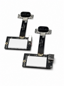
a short-flex design and a long-flex design for different robotics and UAV d…
Frequently Asked Questions About LiDAR Sensor Working
How does a LiDAR sensor measure distance so accurately?
How does solid-state dToF LiDAR work without rotating parts?
Why can a LiDAR sensor fail in sunlight or report unstable measurements?
What is the difference between a LiDAR depth map and a point cloud?
Why is indoor LiDAR range often longer than outdoor range?
What specifications matter most when choosing LiDAR for a robot or drone?
Conclusion and Product Evaluation CTA
Here’s the deal: LiDAR sensor working begins with emitted optical energy, but the job is not finished until the control system makes a sound decision. Between those points, reflected photons have to be detected, nanosecond-scale travel times have to be estimated, calibration must be applied, depth values must be checked, and spatial data must reach the application before it becomes stale. Reliable selection means treating range, sunlight performance, accuracy, field of view, resolution, frame rate, power, weight, interfaces, environmental limits, and failure behavior as one connected system.
The HM-LD1-NV is a compact evaluation candidate for applications that match its documented specifications: 40 x 30 depth resolution, 0.5-25 m indoor ranging capability, 0.2-8 m range at 80 klux, ±3 cm ranging accuracy, 60° x 45° field of view, 10 fps operation, 28 g weight, 1.2 W power consumption, and UART, UDP, and UVC interfaces. Review the HM-LD1-NV product specifications and download the technical brochure before choosing an integration path. Final suitability should be established with the intended target materials, sunlight level, vehicle speed, mounting geometry, compute platform, and failure-response requirements.
📚 References & Further Reading
-
- Industry Standard: Ouster LiDAR Technology Resources
- Positioning Resource: u-blox Positioning and GNSS Resources
- Product Documentation: HM-LD1-NV 3D dToF LiDAR
- Technical Brochure: DTOF SSL HM-LD1-NV Product Brochure
- Related Guide: Sensor LiDAR Drone Guide: How to Choose Lightweight LiDAR for UAV
- Related Guide: Drones for LiDAR: How to Choose a Lightweight, Accurate UAV LiDAR






