

IMU MEMS Sensor Selection Guide: High-Precision IMUs for Robotics and UAVs
An IMU MEMS sensor is easy to treat like a small plug-in component. In the shop, engineers know better. Its performance can determine whether a robot holds its trajectory, whether a UAV maintains stable attitude, and whether an autonomous platform can recover from a temporary GNSS or visual-navigation outage. Selecting an IMU based only on measurement range or headline sampling rate can lead to excessive drift, unstable control loops, poor repeatability, and painful field calibration. The right evaluation starts with the complete inertial performance profile: gyro bias instability, angular random walk, accelerometer bias, velocity random walk, bandwidth, output rate, temperature behavior, mechanical installation, and communication interface.
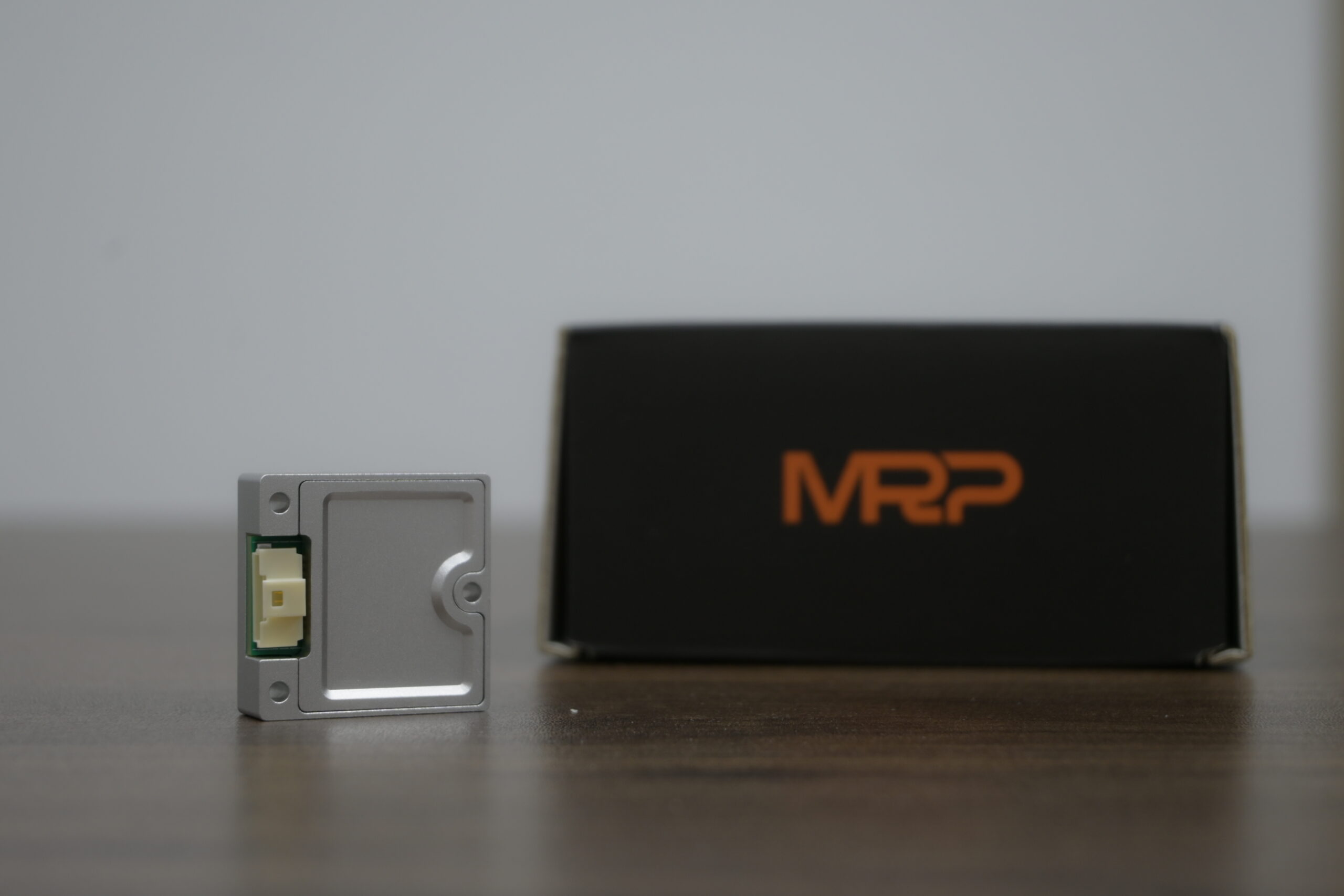
This guide explains how to evaluate an imu mems sensor for demanding robotics and UAV applications. Here’s the deal: every specification has to be tied to an actual engineering decision. The guide applies that selection process to the Industrial High Precision IMU HM-G12. The HM-G12 combines 3-axis gyroscopes, 3-axis accelerometers, an integrated MCU, full-temperature calibration, a stated 1000 Hz output rate, UART communication, and a compact 30 mm × 30 mm × 10.6 mm form factor. Its detailed specification lists gyro bias instability of ≤ 1.4°/h, while the product summary presents 1.4°/h as a typical value. Accelerometer bias instability is specified as 0.016 mg, making the module relevant to high-precision motion control, stabilization, and sensor-fusion systems.
Table of Contents
- 👉 What Is an IMU MEMS Sensor?
- 👉 How MEMS IMU Sensing Works
- 👉 Why IMU Specifications Matter in Robotics and UAVs
- 👉 Key IMU Selection Criteria
- 👉 IMU MEMS Sensor Specifications Explained
- 👉 Installation and Integration Guidance
- 👉 Choosing an IMU for Robotics and UAVs
- 👉 HM-G12 Product Specifications
- 👉 HM-G12 Industrial Features and Applications
- 👉 IMU Sensor Selection Checklist
- 👉 IMU MEMS Sensor FAQ
What Is an IMU MEMS Sensor?
An IMU MEMS sensor is an inertial measurement unit built around microelectromechanical systems technology. A conventional 6-axis MEMS IMU sensor combines three gyroscope axes with three accelerometer axes. The gyroscopes measure angular velocity around the X, Y, and Z axes, while the accelerometers measure specific force along those same axes. Together, these measurements provide the high-rate motion data required by stabilization, control, odometry, and navigation algorithms.
An industrial inertial measurement unit normally includes much more than the microscopic sensing elements. Signal-conditioning circuits and analog-to-digital converters prepare the raw measurements. An embedded processor or MCU may apply calibration coefficients, temperature compensation, axis alignment correction, digital filtering, diagnostics, and data formatting. The resulting measurements are sent to a host controller through a digital interface such as UART, SPI, or CAN, depending on the design.
The term “6-axis” does not mean that the module directly measures position or absolute heading. A 6-axis IMU measures angular rate and specific force. Orientation and navigation are estimated by integrating these measurements and combining them with external references. Without correction, gyro bias causes attitude drift, while accelerometer bias and noise produce velocity and position drift. This is why an IMU sensor for autonomous robots or drones is normally part of a larger sensor-fusion architecture.
IMU Versus INS, AHRS, and GNSS
An IMU supplies inertial measurements, normally angular velocity and acceleration. An AHRS combines inertial measurements with algorithms and often a magnetometer to estimate orientation. An INS uses inertial data and navigation algorithms to estimate position, velocity, and attitude. GNSS provides absolute position and velocity, but its signals can be blocked, reflected, jammed, or temporarily unavailable.
A sensor-fusion system combines the strengths of several technologies. GNSS can constrain long-term position drift. LiDAR can provide geometric information for mapping and localization. Cameras can support visual odometry and feature tracking. Wheel encoders can help estimate ground-vehicle motion, while barometers and magnetometers can provide additional altitude or heading references. The IMU supplies fast propagation between these external observations.
Why MEMS Technology Is Used
MEMS technology is widely used because it provides a practical combination of small size, low mass, low power consumption, fast response, and compatibility with embedded electronics. Those characteristics make a MEMS gyroscope and accelerometer suitable for drones, mobile robots, robotic arms, industrial vehicles, gimbals, surveying platforms, and compact control systems.
MEMS devices also have limitations. Bias drift, temperature sensitivity, vibration, scale-factor error, cross-axis sensitivity, PCB stress, and integration errors can all affect the final navigation result. A high-quality industrial IMU addresses these issues through sensing-element design, mechanical construction, factory calibration, temperature compensation, filtering, health monitoring, and clear installation guidance. Look past the phrase “high precision” and compare the complete product specification.
How MEMS IMU Sensing Works
MEMS Gyroscope Operation
A MEMS gyroscope generally uses a vibrating proof mass. When the platform rotates, the Coriolis effect produces a force perpendicular to the vibration direction. The electronics detect this displacement and convert it into angular-rate data. The gyroscope therefore measures how quickly the platform is rotating, not its absolute angle.
Small gyro bias errors become angle errors after integration. Measurement noise creates short-term uncertainty, while temperature changes can alter bias, scale factor, and alignment. Vibration adds another challenge because motor harmonics, propeller imbalance, gear mesh, fans, pumps, and structural resonance may enter the sensing element as false or distorted motion. These effects make gyro bias instability, angular random walk, bandwidth, and vibration behavior important when selecting an IMU for attitude estimation or stabilization.
MEMS Accelerometer Operation
A MEMS accelerometer measures specific force through the deflection of a suspended proof mass. When stationary, the measurement includes the effect of gravity. During motion, it also includes the platform’s linear acceleration. An accelerometer cannot inherently distinguish gravity from vehicle acceleration, so dynamic motion makes attitude estimation more difficult.
Accelerometer range must be high enough to avoid saturation during normal maneuvers, shocks, or vibration. However, a range that is unnecessarily high may not provide the best resolution for subtle motion. Accelerometer bias and noise are especially important because their errors accumulate into velocity and position errors after integration. Velocity random walk, bias instability, bias stability, bandwidth, and calibration quality should be evaluated together.
Internal Processing and Calibration
The internal MCU in an IMU can manage sensor readout, calibration-coefficient application, temperature compensation, axis alignment, digital filtering, data-packet generation, health monitoring, and fault detection. These functions reduce the amount of low-level processing required from the robot computer or flight controller.
Factory calibration is particularly valuable when the module will operate across a wide temperature range. The HM-G12 is specified for operation from -40°C to +85°C and is described in the supplied product information as being factory calibrated across the full operating temperature range. System designers should still validate the assembled product because enclosure heating, thermal gradients, mounting stress, and rapid temperature transitions can influence system-level behavior.
Why IMU Specifications Matter in Robotics and UAVs
The specifications of an imu mems sensor translate directly into operational behavior. Bias affects long-term drift, noise affects short-term estimation, bandwidth affects response to changing motion, output rate affects control-loop updates, and temperature performance affects repeatability across the operating environment. A useful comparison connects each specification to the job the sensor must perform.
Robotics Use Cases
In a mobile robot, the IMU can support attitude estimation, odometry stabilization, motion compensation for LiDAR and cameras, localization during wheel slip, platform leveling, and abnormal-motion detection. When wheel odometry becomes unreliable on loose flooring or during a sharp maneuver, inertial data can help bridge the interval before another sensor provides a correction.
A LiDAR-equipped robot can use inertial measurements to improve scan registration during fast rotation or acceleration. The IMU provides information about motion between scan samples, helping the navigation system estimate the platform pose more continuously. A robotic arm or end effector can use high-rate angular data to monitor dynamic movement, detect unexpected vibration, and improve motion-control feedback.
IMU data also complements other perception modalities. The article Vision-Only vs. Radar: What Is Better for Robot Perception? discusses how different sensing technologies perform in changing environments. An IMU can complement visual or radar sensing when motion blur, darkness, dust, occlusion, or temporary perception degradation affects another sensor.
UAV Use Cases
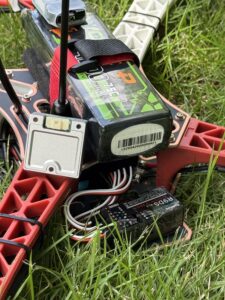
UAV flight controllers use gyro measurements for angular-rate feedback and attitude stabilization. Accelerometer data supports tilt estimation, maneuver detection, and sensor fusion with GNSS, barometers, cameras, LiDAR, and magnetometers. During hover, takeoff, landing, or rapid maneuvering, predictable timing and low latency are essential to control-system stability.
A UAV navigation IMU should be evaluated for gyro range, accelerometer range, bias behavior, noise, vibration sensitivity, temperature stability, output timing, interface compatibility, and mass. A high-speed IMU output can support fast-response loops, but only when the host processor can receive, timestamp, parse, and use the data reliably.
LiDAR and IMU data can also be combined for altitude estimation, mapping, motion compensation, obstacle avoidance, and navigation where GNSS is unreliable. The guide How to Choose a Budget-Friendly LiDAR Sensor for UAVs provides additional context for evaluating LiDAR in UAV systems.
Why High Output Rate Is Not the Same as High Accuracy
Bandwidth describes the frequency range over which the sensor can accurately respond to changing motion. Output rate describes how frequently digital data is transmitted. Internal sampling rate describes how often the sensing electronics may sample internally, while latency describes the time between physical motion and usable output.
The HM-G12 is specified with 200 Hz gyroscope and accelerometer bandwidth and a 1000 Hz output rate in the product summary. That means the module can provide frequent digital updates while its specified measurement bandwidth is 200 Hz. Engineers should not interpret the 1000 Hz output as a 1000 Hz analog measurement bandwidth. Actual performance also depends on filtering, packet timing, jitter, processing delay, and mechanical vibration.
Key IMU Selection Criteria
Selecting a MEMS IMU sensor requires a system-level decision. The most attractive individual number may not matter if the interface is incompatible, the package cannot be mounted rigidly, the temperature range is too narrow, or the host cannot process the output stream.
Accuracy and Stability
Compare gyro bias instability, accelerometer bias instability, bias stability, angular random walk, velocity random walk, scale-factor error, nonlinearity, misalignment, cross-axis sensitivity, and repeatability. Bias instability is especially important for low-dynamic or longer-duration estimation. Noise metrics influence short-term attitude, velocity, and control quality. Always establish whether a published value is typical, maximum, minimum, or guaranteed, and review the test conditions.
Dynamic Range
The HM-G12 provides an accelerometer range of ±16g. Range should be selected according to the expected operating environment. Small indoor robots may experience modest acceleration, while UAVs can experience high acceleration during aggressive maneuvers, impacts, or vibration. Industrial machines may produce short shock events beyond their normal motion.
A range that is too small causes saturation, which can invalidate an estimator during the event. A range that is unnecessarily large may reduce the effective resolution available for subtle motion. The correct choice leaves sufficient headroom while maintaining the noise and resolution needed by the application.
Temperature Performance
Compare the sensor’s operating range with the complete application envelope, including startup, storage, enclosure heating, outdoor exposure, and thermal transients. The HM-G12 is specified for operation from -40°C to +85°C and uses full-temperature calibration according to the supplied product details.
Temperature compensation does not mean every error disappears. It means the device has been characterized and compensated over a defined range. System-level thermal gradients, rapid temperature changes, nearby heat sources, and mounting stress can still affect performance. Validation should be performed on the final mechanical and electrical assembly.
Bandwidth and Output Rate
Low-bandwidth stabilization may prioritize noise reduction, while fast flight-control loops require sufficient bandwidth and low latency. Vibration-heavy platforms require filtering and careful mechanical isolation. A high output rate supports responsive control and sensor fusion, but the host processor must be able to receive, parse, timestamp, and process the data without packet loss or excessive jitter.
Mechanical and Electrical Integration
Review module dimensions, mounting-hole pattern, connector type, signal voltage, supply voltage, current draw, cable routing, grounding, connector retention, and coordinate-frame orientation. The HM-G12 uses a 10-pin connector with a 3.3 V digital signal level, a default UART external data interface, DC 5 ± 0.5 V input, and operating current of no more than 31 mA.
Software and Ecosystem
Before purchase, ask whether the communication protocol is documented, whether packet formats and timestamps are available, and whether a configuration utility, SDK examples, or ROS drivers are provided. Confirm whether output rate can be configured, whether diagnostics and fault flags are available, where calibration data is stored, and whether the device can connect to the intended flight controller or robot computer.
IMU MEMS Sensor Specifications Explained
Angular Random Walk
Angular random walk is a measure of gyroscope noise, commonly expressed in degrees per square root hour. A lower value generally indicates lower short-term angular-rate noise and better attitude-estimation behavior. It is not the same as bias instability. Noise and bias are different error sources, so both values should be compared when evaluating a high-precision IMU.
The HM-G12 specifies angular random walk of ≤ 0.15°/√h. This figure should be considered together with the actual filter settings, bandwidth, vibration environment, and external corrections used by the navigation system.
Gyro Bias Instability
Gyro bias instability describes how the gyro’s zero-rate output changes over time under controlled conditions. This matters because integrating even a small bias produces a growing angle error. The HM-G12 detailed specification lists gyro bias instability as ≤ 1.4°/h, while the product summary presents 1.4°/h as a typical value. This distinction matters when comparing products. A typical value should not be presented as a guaranteed maximum.
Gyro Bias Stability
Gyro bias stability indicates the stability of the gyro offset under specified conditions. The HM-G12 specification is ≤ 4°/h. Terms such as bias stability, bias instability, and in-run bias stability are not always used identically by every manufacturer. Engineers should confirm averaging periods, environmental conditions, test methods, and whether the value is typical or guaranteed.
Orthogonality Error and Cross-Axis Coupling
A perfect three-axis sensor would measure each axis independently. In practice, alignment errors cause motion on one axis to appear on another. The HM-G12 specifies gyro orthogonality error of ≤ 0.05°, and the product summary identifies gyro cross-axis coupling of ≤ 0.05°.
Low cross-axis error is relevant to UAV roll, pitch, and yaw control, robot turning and acceleration estimation, high-precision stabilization, LiDAR motion compensation, imaging systems, and coordinate-frame transformation. The final system still depends on mechanical alignment and the accuracy of the software transformation between the sensor frame and vehicle frame.
Accelerometer Range
The HM-G12 provides a ±16g accelerometer range. This range determines how much specific force can be measured before saturation. Engineers should compare it with expected maneuvering acceleration, motor vibration, shock, and transient events. The range should include practical headroom rather than being selected directly from the average operating value.
Velocity Random Walk
Velocity random walk measures accelerometer noise that contributes to velocity uncertainty after integration. The HM-G12 specifies 0.018 m/s/√h. Low velocity random walk is valuable when inertial propagation must bridge intervals between external corrections, but it does not eliminate long-term drift. Bias, temperature effects, gravity compensation, and sensor-fusion corrections remain important.
Accelerometer Bias Instability and Bias Stability
The HM-G12 specifies accelerometer bias instability of 0.016 mg and accelerometer bias stability of 0.055 mg. Accelerometer bias becomes velocity and position error over time when integrated. Even a small constant offset can create substantial navigation drift if it is not corrected through calibration or sensor fusion.
Bandwidth and Output Rate
Both gyroscope and accelerometer bandwidths are specified at 200 Hz. Bandwidth should be compared with the frequency content of platform motion and vibration. The product summary lists a 1000 Hz output rate. Engineers should verify actual packet frequency, timestamp behavior, jitter, interface throughput, packet-loss handling, host processing requirements, filtering, and total latency.
Temperature Range and Electrical Interface
The HM-G12 operating and storage temperature range is -40°C to +85°C. The module is described as factory calibrated across the full operating temperature range. Its default external data interface is UART ×1. Operating current is ≤31 mA, input voltage is DC 5 ± 0.5 V, and the module uses a 10-pin connector with a 3.3 V digital signal level.
Before connecting the module, confirm the pin assignments, ground arrangement, baud rate, packet format, data units, and input protection requirements. A 5 V supply specification and a 3.3 V digital signal level are different electrical requirements and should be treated separately during integration.
Installation and Integration Guidance
Mechanical Mounting
An accurate sensor can perform poorly if it is installed incorrectly. Mount the IMU on a rigid, stable structure and align its axes with the vehicle or robot coordinate frame. Avoid loose brackets, flexible panels, and uncontrolled adhesive layers. Use the specified screw mounting points, keep the module close to the intended platform reference frame, and avoid excessive torque that may stress the PCB or housing.
Record the mounting orientation and transformation in software. A small mounting-angle error can appear as a persistent coupling between axes, especially when gravity is present. The mounting design should also allow inspection, connector retention, cable strain relief, and thermal evaluation.
Vibration and Resonance
Motor vibration, propeller imbalance, gear mesh, fans, pumps, and structural resonance can contaminate inertial data. Mechanical isolation must be designed carefully because an overly soft mount can introduce relative motion, resonance, and phase lag. A rigid mount may transmit more high-frequency vibration, while an isolation mount may filter useful motion if its response is not characterized.
Mechanical vibration, PCB stress, thermal gradients, and nearby components can all affect gyro and accelerometer readings. A well-designed imu mems sensor module should be installed according to its mounting and calibration guidance. Test the completed assembly under the actual motor speeds, payload conditions, and operating temperatures expected in service.
PCB Stress and Thermal Gradients
The sensing elements should be protected from unnecessary PCB stress. Nearby screws, connectors, stiff adhesives, heat sources, and uneven enclosure pressure can create mechanical strain. Thermal gradients can cause different parts of the assembly to expand at different rates, producing repeatable or changing offsets.
Electrical Noise and Grounding
Use a clean supply voltage with appropriate decoupling and a common ground reference. Where practical, keep signal paths short and separate IMU wiring from high-current motor wiring and fast switching nodes. Shielding or twisted-pair wiring may be useful in electrically noisy systems. Confirm UART logic-level compatibility and provide protection against reverse polarity and overvoltage where the system requires it.
Time Synchronization
For sensor fusion and control, timestamps are as important as data values. Asynchronous readings can create apparent errors when IMU, GNSS, camera, LiDAR, and wheel-encoder data are combined. Verify host-side timestamp accuracy, packet-arrival jitter, clock drift, trigger or synchronization options, and consistent coordinate-frame conventions.
Choosing an IMU for Robotics and UAVs
Selection for Mobile Robots
For mobile robots, prioritize low gyro bias instability, low accelerometer bias, reliable performance during wheel slip, compatibility with LiDAR and camera fusion, compact mounting, stable output over temperature, diagnostic status information, and interface compatibility with the robot computer.
Inertial data can complement visual or radar sensing when motion blur, darkness, dust, occlusion, or temporary perception degradation affects another sensor. This is particularly useful when a robot must continue estimating motion during a short interruption in perception. The IMU does not replace environmental sensing, but it can provide fast motion information between external observations.
Selection for UAVs
For UAVs, prioritize fast and predictable output, low latency, appropriate gyro and accelerometer ranges, low vibration sensitivity, stable performance across changing temperatures, compact mass and footprint, robust flight-controller communication, and fault reporting where required.
A high-speed IMU output supports fast-response control systems when the communication link and software pipeline are designed for it. The UAV navigation architecture should also account for GNSS, barometric, magnetic, camera, and LiDAR measurements. The article How to Choose a Budget-Friendly LiDAR Sensor for UAVs provides related guidance for selecting complementary distance-sensing hardware.
Sensor Fusion
A 6-axis IMU is normally fused with GNSS for absolute position and velocity, LiDAR for geometry and mapping, cameras for visual odometry, wheel encoders for ground-vehicle motion, barometers for altitude trends, magnetometers for heading references, and radar for velocity or obstacle perception.
The HM-LD1 OpenCV Demo illustrates the broader value of combining sensing hardware with software and computer-vision workflows. In a production system, sensor fusion requires correct extrinsic calibration, consistent units, accurate timing, suitable filtering, and a well-defined coordinate convention.
Surveying and mapping workflows may also combine inertial data with positioning and ranging technologies. South Survey is an example of a company associated with surveying, mapping, and positioning technology. HOKUYO provides an example of industrial sensing and LiDAR technology that may be combined with an IMU in robotics applications.
HM-G12 Product Specifications
The Industrial High Precision IMU HM-G12 is a compact industrial-grade 6-axis IMU for drones, robotics, embedded motion-control systems, stabilization, and sensor-fusion applications. It integrates 3-axis gyroscopes, 3-axis accelerometers, and an MCU in a small module measuring 30 mm × 30 mm × 10.6 mm.

The product summary identifies a 1.4°/h typical gyro bias instability, 0.016 mg accelerometer bias instability, ≤0.05° gyro cross-axis coupling, a ±16g accelerometer range, a stated 1000 Hz output rate, full-temperature calibration, and a compact 14 g package. These details should be interpreted with the detailed table and the latest integration documentation.
View Product Details & Pricing ➔
| Category | Parameter | Specification |
|---|---|---|
| Gyroscope | Bandwidth | 200 Hz |
| Angular Random Walk | ≤ 0.15°/√h | |
| Bias Instability | ≤ 1.4°/h | |
| Bias Stability | ≤ 4°/h | |
| Orthogonality Error | ≤ 0.05° | |
| Accelerometer | Accelerometer Range | ±16g |
| Velocity Random Walk | 0.018 m/s/√h | |
| Bias Instability | 0.016 mg | |
| Bias Stability | 0.055 mg | |
| Bandwidth | 200 Hz | |
| Electrical Interface | External Data Interface | UART ×1, default |
| Operating Current | ≤ 31 mA | |
| Input Voltage | DC 5 ± 0.5 V | |
| Interface Type | 10-pin connector, 3.3 V digital signal level | |
| Mechanical Dimensions | Dimensions | 30 mm × 30 mm × 10.6 mm |
| Operating Temperature | -40°C to +85°C | |
| Weight | 14 g | |
| Storage Temperature | -40°C to +85°C |
The product summary also identifies a 1000 Hz output rate, a typical gyro bias instability of 1.4°/h, full-temperature calibration, and a 6-axis inertial output. Confirm the latest datasheet and interface documentation for final integration values, packet definitions, configuration options, and test conditions.
HM-G12 Industrial Features and Applications
High-Precision Inertial Performance
The HM-G12 integrates 3-axis gyroscopes, 3-axis accelerometers, and an MCU in a 30 mm × 30 mm × 10.6 mm module. Its 1.4°/h typical gyro bias instability and 0.016 mg accelerometer bias instability are relevant to systems that need stable short-term inertial propagation and repeatable motion data.
Full-Temperature Calibration
Calibration from -40°C to +85°C supports deployment in outdoor robotics, UAVs, industrial equipment, and changing thermal environments. System designers should still account for enclosure heat, local thermal gradients, warm-up time, mounting stress, and rapid changes in ambient temperature.
Functional Safety and Fault Detection
The supplied product details describe redundant architecture and continuous sensor-status monitoring. This should be presented as a reliability feature rather than an unsupported certification claim. HM-G12 is designed for reliable operation with built-in status monitoring and fault-detection functions intended to help system integrators identify abnormal sensor conditions.
Formal safety certification should not be inferred unless certification documentation, applicable standards, diagnostic coverage, and failure-rate information are available. The complete safety architecture remains the responsibility of the system integrator.
High-Speed Output
The stated 1000 Hz real-time output supports fast-response motion-control systems, provided that the host interface and software pipeline can process the data at the required rate. Engineers should evaluate packet timing, timestamps, filtering, latency, CPU load, buffer capacity, and data-integrity checks before final deployment.
Compact Integration
The 14 g weight and 30 mm × 30 mm × 10.6 mm dimensions make the module suitable for applications where enclosure space and payload mass matter. The 10-pin connector, UART interface, screw mounting, 5 V input, and 3.3 V digital signal level provide defined starting points for embedded integration. Final wiring should follow the latest product documentation.
Application Examples
The HM-G12 can be evaluated for UAV flight stabilization, autonomous mobile robots, industrial AGVs and AMRs, robotic arms and manipulators, LiDAR motion compensation, camera and gimbal stabilization, surveying and mapping platforms, embedded motion-control systems, and navigation sensor-fusion platforms. Suitability depends on the complete system design, including vibration, temperature, mounting, software, calibration, and external reference sensors.
View Product Details & Pricing ➔
IMU Sensor Selection Checklist
- ✅ Is the product a true 6-axis IMU or an AHRS or INS with additional processing?
- ✅ What are the gyro bias instability and angular random walk values?
- ✅ Are the published values typical, maximum, minimum, or guaranteed?
- ✅ What are the accelerometer bias and velocity random walk values?
- ✅ Is the dynamic range sufficient for expected acceleration and shock?
- ✅ Does the bandwidth match the control loop and motion profile?
- ✅ Is the output rate high enough, and what is the actual latency?
- ✅ Is the operating temperature range suitable?
- ✅ Was calibration performed across the full temperature range?
- ✅ Are scale factor, alignment, cross-axis, and nonlinearity data available?
- ⚙️ Is the sensor mechanically isolated from vibration and PCB stress?
- ✅ Does the package fit the available mounting space?
- ⚙️ Is the power supply compatible?
- ⚙️ Are the UART signal levels compatible with the host?
- ⚙️ Is the connector documented and mechanically secure?
- ⚙️ Are timestamps, packet checksums, and diagnostic flags available?
- ✅ Can the output be integrated with ROS, a flight controller, or a custom embedded system?
- ✅ Is the IMU supported by a clear datasheet and integration guide?
- ✅ Can the supplier provide samples, technical support, and production consistency?
IMU MEMS Sensor FAQ
Why should MEMS sensors be physically isolated from the rest of an IMU PCB?
How do I choose an accurate IMU for robotics or UAV navigation?
Can a MEMS IMU provide reliable orientation and navigation by itself?
What is the difference between IMU bandwidth and output rate?
Why is gyro bias instability important for UAV attitude control?
Does a higher accelerometer range always mean a better IMU?
How should an IMU be integrated with LiDAR or camera navigation?
What should I verify before connecting a UART IMU to a robot controller?
How does temperature calibration improve IMU performance?
What does functional safety or fault detection mean in an industrial IMU?
Selecting an imu mems sensor requires a system-level comparison of accuracy, stability, bandwidth, output rate, temperature performance, interface, mechanical integration, and sensor-fusion compatibility. The HM-G12 combines high-precision 6-axis inertial sensing, full-temperature calibration, a stated 1000 Hz output rate, UART communication, and a compact industrial package for robotics, UAVs, and embedded control systems.
View Product Details & Pricing ➔
📚 References & Further Reading
- Product Reference: Industrial High Precision IMU HM-G12






