Drone Detect and Avoid: Build Safer UAV Obstacle Avoidance with Compact dToF LiDAR
Modern UAVs are no longer staying out in clean, open fields where there is plenty of room to recover from a mistake. They are flying through warehouses, under bridges, near power infrastructure, around construction sites, inside forests, along tunnels, and through low-altitude inspection corridors. In those places, a drone detect and avoid system is not a luxury feature. It is a practical safety layer that helps keep the aircraft away from walls, cables, tree limbs, structural beams, machinery, other equipment, and terrain. GPS may be weak. Lighting may be poor. Visual texture may be missing. And look, when a compact UAV is flying close to valuable assets, pilot reaction time is not always enough.
Here’s the deal: drone obstacle avoidance is moving away from simple proximity alarms and toward real-time depth sensing, onboard perception, and tighter flight-control integration. For compact UAV platforms, solid-state dToF LiDAR can hit a useful middle ground between bulky mechanical scanning LiDAR and camera-only perception. A module such as the DTOF Solid State LiDAR HM-LD1 can provide real-time depth maps and 3D point cloud data in a compact 28 g package, with a 60° horizontal by 45° vertical field of view, ±3 cm ranging accuracy, and UART/UDP/UVC interfaces for embedded development.
Table of Contents
- 👉 What Is Drone Detect and Avoid?
- 👉 Why UAVs Need Better Obstacle Avoidance
- 👉 How Drone Detect and Avoid Works
- 👉 Sensor Options for Drone DAA Systems
- 👉 Why dToF LiDAR Fits Compact UAV Obstacle Avoidance
- 👉 DTOF Solid State LiDAR HM-LD1 Product Specifications
- 👉 Integration Architecture for UAV Developers
- 👉 Drone Detect and Avoid Use Cases
- 👉 Engineering Design Considerations for Drone Obstacle Avoidance
- 👉 Limitations and Sensor Fusion in Drone Detect and Avoid
- 👉 Buying Checklist for Drone Obstacle Avoidance LiDAR
- 👉 FAQ
What Is Drone Detect and Avoid?
Drone detect and avoid, often shortened to DAA, is the combination of sensing, perception, decision-making, and control action that helps a UAV reduce collision risk. In small and medium UAV engineering, the phrase usually means local obstacle awareness: detecting walls, ceilings, poles, racks, trees, terrain, machinery, bridge members, and other objects near the aircraft. In broader aviation language, detect-and-avoid can also mean avoiding aircraft or other drones in shared airspace. Those two jobs are related, but they are not the same job.
For compact UAVs, DAA is usually local and short-range. The goal is to prevent collisions during navigation, landing, inspection, indoor flight, low-altitude operation, and close-proximity work. The drone may not need to know whether the object is a rack, a wall, or a concrete column. It may only need to know that something is close enough to slow down, stop, climb, descend, yaw, or re-route. That is where depth sensing, LiDAR obstacle avoidance, and real-time distance measurement earn their keep.
Three Core Advantages — Elevating Perception Capability
Local Obstacle Avoidance vs Airspace Detect-and-Avoid
Local obstacle avoidance is the onboard perception problem: what is around the drone right now, how far away is it, and is the aircraft moving toward it? A front-facing LiDAR sensor can help detect a nearby wall or structural member. A downward-facing depth sensor can help hold altitude above uneven ground. A side-facing module can help maintain clearance during wall-following or inspection work. These are direct geometric sensing tasks, and they are exactly the kind of work compact dToF LiDAR is built to support.
Airspace detect-and-avoid is a wider surveillance and regulatory problem. It may involve Remote ID, ADS-B in applicable aviation contexts, RF detection, radar, optical tracking, and ground-based monitoring. A compact onboard dToF LiDAR module is not a substitute for air traffic management or long-range drone tracking. It is better understood as a local perception sensor that helps a UAV respond to nearby physical obstacles within its range and field of view.
Detection, Classification, and Avoidance Are Different Layers
In the shop, people sometimes talk about “the obstacle avoidance sensor” as if the sensor alone solves the problem. It does not. A practical drone detect and avoid system is a stack. First comes detection: sensing that an object or surface exists. Next is localization: estimating where that obstacle sits relative to the aircraft. Then comes tracking: deciding whether the object, the drone, or both are moving in a way that increases risk. After that, decision-making selects the response. The last layer is control execution, where the command actually reaches the flight controller and the aircraft behaves as expected.
Classification can help when a camera or AI model needs to identify people, vehicles, landing markers, or inspection targets. But classification is not always required for basic collision prevention. If the drone is about to hit a wall, a pipe rack, a tree trunk, or a bridge beam, reliable distance measurement may matter more than knowing the object’s name.
Why UAVs Need Better Obstacle Avoidance
UAVs are being pushed into environments where manual piloting is hard and GNSS-based navigation is not enough. Industrial inspection often means flying close to bridges, dams, power lines, tanks, conveyors, cranes, tunnels, solar farms, warehouses, and active construction sites. These locations are full of tight clearances, repeated structural patterns, metal interference, reflective surfaces, moving equipment, shadows, and sudden lighting changes. Even a good pilot can misjudge distance when the only view is a camera feed.
Low-cost drones often depend heavily on GNSS and vision. That can work well in clean outdoor environments, but GNSS can degrade near metal structures, under bridges, indoors, in urban canyons, and close to large infrastructure. Camera-only systems can be powerful, but they can struggle with blank walls, low texture, motion blur, low light, glare, fog, dust, repetitive patterns, transparent surfaces, and harsh contrast. Compact LiDAR adds direct geometric distance measurement independent of visual texture, making it useful as part of a UAV obstacle avoidance system. For a broader comparison of sensing technologies, see our guide on obstacle avoidance sensors for robots and drones.
Common UAV Collision Scenarios
Many drone crashes are not dramatic high-speed events. They happen during slow, close-range jobs. A UAV may back away from an inspection target while the camera is still facing forward, leaving the rear direction under-monitored. It may drift sideways in wind and contact a wall, tree branch, railing, or scaffold. It may approach cables, trusses, beams, and thin structures that are hard to see in a live video feed. During landing, it may descend onto uneven ground, vegetation, a curb, a pallet, or nearby equipment.
Indoor aircraft face their own headaches. Warehouses and factories contain racks, ceilings, light fixtures, conveyors, columns, forklifts, machines, and people. GNSS is usually unavailable, and visual positioning can be challenged by repeated patterns or low lighting. A depth sensor is not a complete autonomy system by itself, but it gives the aircraft a more honest measurement of nearby geometry.
Why Weight and Power Matter on Drones
Every gram added to a UAV affects endurance, center of gravity, vibration behavior, payload capacity, and thermal design. A sensor that works beautifully on a ground robot may be too heavy or too power-hungry for a small drone. Mechanical scanning LiDAR can provide wide coverage, but the size, cost, moving parts, and power draw may not fit compact UAV platforms. On the other end, very low-cost range sensors may have limited range, narrow field of view, or insufficient data for directional avoidance.
Power matters just as much. A perception stack draws energy from the same battery that supports propulsion, compute, communication, and payload operation. A lower-power depth sensor gives engineers more room in the design. The HM-LD1’s 1.2 W power consumption and 28 g weight make it a practical candidate for compact UAV designs where payload and energy budgets are tight.
How Drone Detect and Avoid Works
A complete drone detect and avoid pipeline starts with sensing. The system collects distance, image, IMU, positioning, velocity, and flight-state data. Depending on the architecture, that may include LiDAR, cameras, ultrasonic sensors, radar, optical flow, GNSS/RTK, barometers, and flight controller telemetry. The data is then cleaned up: timestamps are synchronized, invalid measurements are rejected, mounting angle is compensated, and sensor readings are transformed into the drone’s coordinate frame.
Next comes perception. The UAV may generate a depth map, point cloud, occupancy grid, obstacle list, or free-space estimate. The risk layer evaluates distance-to-obstacle, time-to-collision, safety clearance, vehicle speed, available escape direction, and control limits. Planning converts that risk into action: slow down, stop, climb, descend, yaw away, sidestep, or choose another route. Finally, the command moves through the companion computer or flight controller interface and becomes real aircraft motion.
Depth Map-Based Obstacle Detection
A depth map provides distance values across a two-dimensional grid. Each pixel or cell represents a measured distance in a direction within the sensor’s field of view. For embedded drone collision detection, this format is convenient because it behaves like an image and can be divided into zones. A developer might split the field of view into left, center, and right regions, calculate the nearest valid distance in each zone, and then slow or turn away when one zone crosses a safety threshold.
The HM-LD1 has a 40 × 30 resolution, creating a compact depth image suitable for lightweight processing. That is not camera-level resolution, and it is not meant to be. For basic avoidance, lower data volume can be a benefit. It reduces compute load, simplifies threshold logic, and helps the system respond predictably in real time.
Point Cloud-Based Environmental Awareness
A point cloud represents measured surfaces as 3D points. This supports more advanced perception work such as geometry analysis, free-space estimation, simple mapping, SLAM support, and clearance checking. Point clouds are useful when a UAV needs to understand the shape and orientation of nearby structures, not just the nearest range value. For example, an inspection drone approaching a bridge beam may benefit from estimating the plane or edge of the surface ahead.
Depth maps and point clouds are not competing ideas. They are two different ways to represent related distance data. A depth map is great for fast zone-based avoidance. A point cloud is useful for spatial reasoning. Many teams prototype with point cloud visualization, then deploy simpler depth-zone logic for production because it is easier to validate and easier to run on embedded hardware.
Time-to-Collision and Safety Margins
Detection range must be judged together with vehicle speed, frame rate, processing latency, braking distance, and motor response. A 10 fps sensor updates every 100 milliseconds. If the aircraft is moving slowly during inspection, that may be completely workable. If the aircraft is flying fast, it can travel a meaningful distance between updates, and the design needs more margin.
Time-to-collision is a useful metric because it connects distance to relative speed. A stationary wall 4 meters away is not much of a problem if the drone is hovering. The same wall becomes a serious problem if the aircraft is moving quickly toward it. Good drone detect and avoid logic should adjust thresholds based on flight mode and speed. It should also avoid triggering on a single noisy pixel. Use filtering, confidence logic, and conservative control limits.
Sensor Options for Drone DAA Systems
No single sensor is perfect for every drone detect and avoid application. The right choice depends on flight speed, environment, payload budget, required field of view, lighting, obstacle type, compute capacity, and cost. Cameras provide rich visual information. Ultrasonic sensors are simple and cheap for very short-range sensing. mmWave radar can work in dust, fog, and poor lighting. Mechanical LiDAR can provide wide spatial coverage. Solid-state dToF LiDAR offers compact direct depth measurement for short-range obstacle detection and UAV depth sensing.
Companies such as Innoviz Technologies and HOKUYO show how mature LiDAR has become across autonomous mobility, robotics, and industrial automation. UAV developers can borrow lessons from those markets, but they still need to respect drone-specific constraints: weight, vibration, power, field of view, and integration simplicity.
| Sensor Type | Strengths | Limitations | Typical UAV Use |
|---|---|---|---|
| Camera / Stereo Vision | Rich visual information, object recognition, low hardware cost | Depends on lighting, texture, calibration, and compute | Navigation, mapping, visual SLAM, inspection imaging |
| Ultrasonic Sensor | Low cost, simple short-range distance sensing | Narrow use cases, limited range, affected by angle and material | Landing assistance, simple altitude hold |
| mmWave Radar | Works in dust, fog, and poor lighting; detects velocity | Lower spatial resolution than LiDAR/camera in many compact systems | Collision warning, moving-object detection |
| Mechanical LiDAR | Wide scanning coverage, strong 3D mapping capability | Higher cost, size, weight, and moving parts | Mapping, autonomy research, larger UAVs |
| Solid-State dToF LiDAR | Compact, lightweight, direct distance measurement, depth map output | Range and FOV must be matched to speed and application | Short-range obstacle avoidance, altitude hold, terrain following |
Camera-Only Avoidance
Camera-based systems are attractive because they provide rich scene information and support object recognition, visual SLAM, landing marker detection, and inspection documentation. Stereo vision can estimate depth when the cameras are calibrated and the environment has enough texture. Monocular cameras can support object detection or optical flow, but they often need more assumptions and more compute.
The weak spot is reliability under ugly real-world conditions. Blank walls, repeated warehouse racks, glossy surfaces, motion blur, low light, sudden glare, fog, and dust can reduce performance. Camera-only avoidance can be very capable, but for industrial UAV obstacle avoidance, engineers often add LiDAR or radar to provide another physical distance measurement.
LiDAR-Based Avoidance
LiDAR is an active sensing method. Instead of relying entirely on ambient light or visual texture, it emits light and measures return signals to estimate distance. That makes LiDAR valuable for geometric obstacle detection. A UAV LiDAR sensor can help identify that a surface is close, even when the surface has little visual texture. It also provides distance data in a format that works well for safety thresholds and flight-control logic.
LiDAR still has limits. Field of view, range, reflectivity, sunlight, transparent materials, and angle of incidence can affect results. Mechanical LiDAR may be too large for small aircraft, while compact solid-state LiDAR must be matched carefully to the intended range and coverage. In other words, choose the tool for the actual job, not just the biggest number on the datasheet.
Sensor Fusion Is Usually the Best Architecture
Robust drones often combine LiDAR, cameras, IMU, GNSS/RTK, barometer, optical flow, and flight controller data. LiDAR provides geometry. Cameras provide visual context and classification. IMU data provides attitude and acceleration. GNSS or RTK provides global position when available. For positioning-focused UAV systems, see our article on GPS RTK for robotics, drones, and surveying.
Sensor fusion does not mean stuffing every sensor possible onto the aircraft. It means combining complementary inputs so the UAV is not betting the whole mission on one fragile signal. A downward dToF LiDAR can support altitude hold, a camera can support inspection imaging, and RTK can support repeatable outdoor mission paths. Each sensor has a job.
Why dToF LiDAR Fits Compact UAV Obstacle Avoidance
dToF means direct Time-of-Flight. The sensor emits light pulses and measures how long reflected photons take to return. Since the speed of light is known, the sensor can calculate distance from the measured travel time. SPAD-based dToF sensors use sensitive single-photon avalanche diode technology to detect returning light and generate depth measurements in compact packages.
For compact UAVs, solid-state dToF modules are attractive because they deliver usable depth maps and 3D point cloud data without a rotating scanner. They are typically easier to package than mechanical LiDAR, more direct than camera-only depth estimation, and more spatially informative than a single-point rangefinder. That combination makes them useful for short-range drone collision avoidance, altitude hold, terrain following, and close-proximity inspection.
What Direct Time-of-Flight Means
Direct Time-of-Flight measures how long light takes to travel from the emitter to the target and back to the receiver. The sensor does not need to infer distance from object size or image texture. It measures distance physically through timing. In a depth-sensing module, this process is repeated across an array or sensing grid so the output contains many distance measurements across the field of view.
This is useful when the drone needs immediate awareness of nearby geometry. When approaching a wall, descending toward uneven ground, or flying along a bridge surface, a depth map provides actionable distance information with less dependence on visual features.
Why Solid-State Design Matters on UAVs
Solid-state design matters because drones are vibration-sensitive, weight-sensitive, and space-constrained. A sensor with no rotating scanner mechanism can be easier to mount and protect. It can be positioned forward, downward, or sideways depending on the mission. It can also reduce mechanical complexity compared with spinning sensors, which may be harder to integrate into compact airframes.
That said, solid-state LiDAR is directional. A 60° × 45° field of view is not full 360° coverage. But many UAV tasks do not need full coverage from one sensor. They need the right coverage in the right direction: forward during approach, downward during landing, or sideways during wall-following inspection.
Depth Image Output for Embedded Processing
A lower-resolution depth image can be easier to process on embedded systems than high-bandwidth camera data or dense scanning LiDAR output. Developers can divide the image into zones, filter invalid pixels, calculate minimum or percentile distances, and apply speed-dependent thresholds. This supports practical decision-making without requiring a large onboard GPU.
For UAV OEMs and robotics engineers, the right question is not “Which sensor produces the most data?” The better question is “Which sensor gives me the right data for the control decision, inside my payload, power, and compute budget?” For many compact UAV jobs, dToF LiDAR fits that requirement nicely.
DTOF Solid State LiDAR HM-LD1 Product Specifications
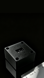
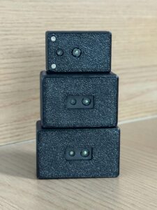
The DTOF Solid State LiDAR HM-LD1 is a compact SPAD dToF LiDAR module designed for real-time depth sensing, obstacle detection, robotic vision, and UAV perception development. Its small size, low weight, and multi-interface support make it suitable for compact drones, mobile robots, embedded platforms, and prototyping systems that require depth maps or point cloud data without the size and complexity of mechanical LiDAR.
HM-LD1 delivers real-time depth images and 3D point cloud data for accurate environmental perception. It supports indoor or nighttime ranging up to 25 m and outdoor daytime ranging up to 8 m, making it applicable to obstacle avoidance, distance detection, autonomous navigation, smart inspection, and robotic vision development. With UVC, UDP, and UART interfaces, the module can be integrated with PCs, Raspberry Pi-style embedded platforms, flight controllers, and onboard compute systems. MRP also provides SDKs for x86 Windows, x86 Linux, and ARM Linux to support development across multiple operating systems and architectures.
Learn more about the module here: DTOF Solid State LiDAR HM-LD1
| DTOF Solid State LiDAR HM-LD1 Specifications | |
|---|---|
| Product Name | DTOF Solid State LiDAR HM-LD1 |
| Technology | Solid-state LiDAR based on SPAD dToF technology |
| Dimensions | 43.5 mm × 30 mm × 26.5 mm |
| Weight | 28 g |
| Ranging Capability | Indoor: 0.5–25 m; Outdoor: 0.2–8 m |
| Ranging Accuracy | ±3 cm |
| Field of View | 60° horizontal × 45° vertical |
| Resolution | 40 × 30 |
| Frame Rate | 10 fps |
| Interfaces | UART / UDP / UVC |
| Operating Temperature | -20 ℃ to 60 ℃ |
| Power Consumption | 1.2 W |
| Development Support | SDKs for x86 Windows, x86 Linux, and ARM Linux |
| Typical Applications | UAV obstacle avoidance, altitude hold, terrain following, robot navigation, SLAM support, distance detection, smart inspection, robotic vision development |
View Product Details & Pricing ➔
Need a compact dToF LiDAR for UAV obstacle avoidance?
Explore HM-LD1 for real-time depth maps, point cloud output, 28 g weight, 60° × 45° FOV, ±3 cm ranging accuracy, and UART/UDP/UVC integration for embedded drone perception development.
Integration Architecture for UAV Developers
Integrating a UAV LiDAR sensor is a system-design job, not just a wiring job. The developer has to decide where the sensor mounts, what region it monitors, how the data is processed, how the perception stack communicates with the flight controller, and how conservative the avoidance behavior should be. A drone designed for forward inspection may need front-facing collision detection. A landing-assistance drone may need downward sensing. An indoor warehouse UAV may need multiple directions of coverage.
Mounting Position and FOV Coverage
A front-facing HM-LD1 can support forward collision warning and approach control. This is useful when the drone moves toward walls, racks, bridge structures, or inspection targets. A downward-facing module can support altitude hold, landing assistance, and terrain following. A side-facing module can support wall following, corridor navigation, or inspection clearance. Multi-directional configurations can provide broader coverage, but they also add payload, wiring, calibration, power draw, and processing requirements.
Because the HM-LD1 has a 60° horizontal by 45° vertical field of view, mounting angle matters. Engineers should verify that the sensor’s field of view covers the expected motion direction and obstacle location. A sensor pointed too high may miss low obstacles. A sensor pointed too low may overreact to the floor during forward flight.
Interface Selection: UART, UDP, or UVC
HM-LD1 supports UART, UDP, and UVC interfaces. UART can be useful for embedded controller integration and lightweight data pipelines. It is often appropriate when the system needs simplified range or depth data transferred to a microcontroller or autopilot-adjacent processor. UDP fits networked onboard computers, Linux companion computers, robotics middleware, and perception pipelines where multiple sensors may communicate over network-style interfaces. UVC can be convenient for PC-style development and camera/depth streaming workflows.
The interface should match the compute architecture. A drone that uses a companion computer for perception may benefit from UDP or UVC during development. A minimal embedded system may prefer UART if the avoidance logic is simple and bandwidth requirements are modest.
Companion Computer vs Flight Controller Integration
A common architecture is LiDAR to companion computer, companion computer to obstacle detection algorithm, and obstacle detection algorithm to flight controller. The companion computer handles depth map filtering, zone analysis, point cloud processing, logging, and decision logic. It then sends high-level commands such as slow down, stop, climb, or reject movement in a blocked direction.
Another architecture is LiDAR to embedded controller, then warning or simplified control signal to the flight controller. This can reduce compute requirements but may limit advanced perception features. During development, teams often connect the module to a PC for visualization, algorithm tuning, and test logging before moving the system onto the aircraft.
SDK and Platform Support
MRP offers SDKs for x86 Windows, x86 Linux, and ARM Linux. That matters because many teams prototype on desktops, test on Linux workstations, and deploy on ARM-based embedded boards. Development support can reduce integration time, especially when teams need to move from proof-of-concept testing to field trials and production deployment.
Basic Avoidance Logic Example
A simple drone obstacle avoidance algorithm can divide the depth map into zones, ignore invalid pixels, compute a minimum or percentile distance for each zone, and trigger a response when the distance falls below a threshold. The center zone may trigger braking. The left and right zones may influence yaw or sidestep decisions. Thresholds should not be fixed without considering speed. Slow inspection mode can use shorter thresholds, while faster flight needs more clearance.
More advanced systems combine depth history, vehicle velocity, attitude, and predicted stopping distance. They may also use confidence filtering and outlier rejection so a single unstable reading does not create an unnecessary maneuver. Safety behavior should be conservative, repeatable, and tested in real flight conditions.
Drone Detect and Avoid Use Cases
Drone detect and avoid systems are useful across commercial and industrial UAV applications. The most valuable cases are usually the ones where the aircraft must fly close to objects, maintain a precise distance, or operate where GPS and camera-only perception are not reliable enough.
UAV Altitude Hold
A downward-facing depth sensor can provide local distance-to-ground data. This is useful when barometric altitude is not enough or when the drone flies near uneven terrain, platforms, stairs, loading docks, vegetation, or structures. Depth-based altitude hold can help the aircraft maintain a more consistent distance from the surface below, especially during low-altitude operation.
Terrain Following
Terrain following requires the UAV to maintain a controlled height above irregular surfaces. This matters for inspection, agriculture, mining, mapping, and environmental monitoring. A compact dToF LiDAR can assist by providing terrain-relative distance measurements. For slow to moderate flight speeds, HM-LD1’s real-time depth maps can support terrain-aware control logic when integrated properly with the flight controller.
Bridge, Dam, and Infrastructure Inspection
Infrastructure inspection often requires flying near concrete, steel beams, tunnels, walls, cables, and vertical surfaces. The HM-LD1’s outdoor daytime range up to 8 m can be useful in short-range inspection contexts where the drone approaches an asset carefully. Its depth maps and point clouds can help the UAV maintain clearance and reduce operator workload during close-proximity inspection.
Indoor Warehouse and Factory UAVs
Indoor UAVs often operate without reliable GNSS. Warehouses and factories include racks, ceilings, machines, columns, lighting, conveyors, pallets, and people. Camera systems are useful, but lighting and repetitive patterns can challenge visual algorithms. A solid-state dToF LiDAR module can provide direct depth data for local obstacle awareness, helping drones navigate slow indoor routes or maintain clearance during inspection tasks.
Robot and UAV Shared Perception Development
Because HM-LD1 supports PCs, Raspberry Pi-style embedded platforms, flight controllers, and Linux-based development environments, it can support both robot and UAV perception development. Teams building mobile robots and drones may use the same depth-sensing module family across platforms, simplifying software reuse, testing, and procurement.
Engineering Design Considerations for Drone Obstacle Avoidance
Engineering a reliable drone collision avoidance system takes more than choosing a sensor with a good maximum range. UAV developers need to consider speed, field of view, lighting, reflectivity, filtering, mounting, environmental protection, power, latency, and flight controller behavior. The system should be validated in the actual target environment, with real surfaces and real flight modes.
Match Detection Range to Flight Speed
The faster the drone flies, the more detection range it needs. A 10 fps sensor updates every 100 milliseconds. The aircraft also needs time for processing, planning, communication, and motor response. A drone moving slowly during inspection can operate with shorter detection distances than a fast outdoor UAV. Engineers should calculate how far the aircraft travels between frames, add processing latency, and include braking or maneuver distance.
Understand Field of View
A 60° × 45° FOV is useful for directional awareness, but it does not provide full 360° protection. If the UAV can move sideways, backward, or rotate in tight spaces, obstacles may appear outside the sensor’s view. Omnidirectional protection may require multiple sensors or a mix of LiDAR, cameras, radar, and optical flow. The correct configuration depends on the mission and expected motion envelope.
Use Confidence Filtering and Outlier Rejection
Depth sensors can produce invalid or noisy readings under certain surface angles, reflectivity levels, environmental conditions, or sunlight situations. Avoidance algorithms should not react blindly to a single pixel. Common approaches include rejecting invalid pixels, using percentile distances instead of absolute minimums, checking temporal consistency, and requiring multiple neighboring cells to confirm an obstacle.
Plan for Outdoor Lighting Conditions
HM-LD1 supports outdoor ranging up to 8 m and is described as capable of accurate measurement outdoors even under clear summer daylight conditions around 80,000 lux. Engineers should still test the sensor against the real materials, sun angles, reflectivity, and mounting positions expected in the mission. Outdoor optical sensing can be affected by bright sunlight, dark objects, reflective surfaces, transparent materials, water, and steep incident angles.
Mechanical Integration
Mechanical integration should cover rigid mounting, vibration control, cable strain relief, airflow, sensor window cleanliness, and center-of-gravity impact. If the drone operates outdoors, the design may also require environmental protection appropriate to the aircraft and mission. The sensor should be mounted where propellers, landing gear, payloads, or the airframe do not obstruct the field of view.
Power Budget
HM-LD1’s power consumption is 1.2 W. That is modest compared with many heavier perception stacks, but it still belongs in the aircraft energy budget. Power draw affects endurance, thermal behavior, voltage regulation, and wiring. Production UAVs should evaluate the sensor together with companion computers, cameras, radios, payloads, and flight controller electronics.
Limitations and Sensor Fusion in Drone Detect and Avoid
No single sensor solves every UAV avoidance problem. LiDAR may have field-of-view and range limits. Camera systems add semantic understanding and visual navigation, but they depend on lighting and texture. GNSS/RTK provides global positioning where available, but it can degrade indoors or near structures. IMU and flight controller data provide attitude and motion state, but they do not directly measure obstacles. mmWave radar can help in dust, fog, or moving-object detection scenarios, but compact radar may have lower spatial resolution than LiDAR or cameras.
Sensor fusion is the practical path for safety-focused UAV design. A compact dToF LiDAR can be excellent for local geometry, while vision adds classification and inspection imagery, RTK adds repeatable positioning, and the flight controller provides state estimation. If your system includes cameras and LiDAR modules together, this related article discusses whether phone camera LiDAR can cause damage and helps clarify common misconceptions about compact LiDAR sensing.
Why LiDAR Is Not the Same as Drone Tracking
Onboard dToF LiDAR detects nearby surfaces and objects inside its range and field of view. It does not identify aircraft identities, decode Remote ID, track operators, or provide airport-style airspace surveillance. A compact LiDAR module can support local collision awareness if an object enters its sensing region, but it is not a complete counter-UAS or long-range aircraft detection system.
When to Add Vision
Vision should be added when the UAV needs classification, visual SLAM, landing marker recognition, inspection documentation, or human-readable imagery. A camera can identify what an object is, while LiDAR can help measure where it is. Combining the two can improve practical autonomy when compute and payload budgets allow.
When to Add RTK GNSS
RTK GNSS is useful for accurate global positioning, repeatable missions, mapping, and outdoor autonomy where satellite reception is reliable. It is not a replacement for local obstacle avoidance because global position does not reveal unexpected branches, cables, vehicles, people, or construction changes. For outdoor drones, RTK and LiDAR solve different but complementary problems.
Buying Checklist for Drone Obstacle Avoidance LiDAR
When evaluating a LiDAR module for drone detect and avoid, procurement teams and engineering teams should review both the datasheet and the mission requirements. A suitable module for one UAV may not be suitable for another if the speed, field of view, power budget, or environment differs.
- ✅ Is the module light enough for the UAV payload budget?
- ✅ What are the indoor and outdoor ranging limits?
- ✅ Is the field of view suitable for the intended direction of travel?
- ✅ Does the frame rate support the expected flight speed and stopping distance?
- ✅ Does the output format support depth maps or point clouds?
- ⚙️ Which interfaces are available: UART, UDP, or UVC?
- ⚙️ Does the supplier provide SDKs?
- ⚙️ Can the module run with the target OS and CPU architecture?
- ✅ What is the power consumption?
- ✅ What is the operating temperature range?
- ✅ Is the supplier able to provide integration support?
- ✅ Is customization available for production requirements?
- ⚙️ Has the module been tested with the target surface types and lighting conditions?
For teams developing compact UAV obstacle avoidance, altitude hold, terrain-following, or short-range inspection systems, the HM-LD1 is worth evaluating because it combines a compact 28 g design, 40 × 30 depth resolution, 10 fps frame rate, ±3 cm ranging accuracy, and UART/UDP/UVC support.
View Product Details & Pricing ➔
We’ve recently been testing the HM-LD1 compact dToF LiDAR in a variety of r…
FAQ
What sensor should I use for drone obstacle avoidance or collision detection?
Can a drone detect and avoid other drones mid-air?
Is it possible to track nearby drones or know their location like an airport tower?
What is the difference between drone obstacle avoidance and drone detect and avoid?
How much LiDAR range does a drone need for obstacle avoidance?
Is 10 fps enough for drone obstacle avoidance?
Can dToF LiDAR work outdoors on drones?
Can one LiDAR sensor provide full drone collision avoidance?
What outputs should developers use: depth map or point cloud?
How should HM-LD1 be connected to a drone platform?
📚 References & Further Reading
- Industry Standard: Innoviz Technologies
- Industry Standard: HOKUYO
- Product Details: DTOF Solid State LiDAR HM-LD1
- Related Guide: Obstacle avoidance sensors for robots and drones
- Related Guide: GPS RTK for robotics, drones, and surveying
- Related Guide: Phone camera LiDAR damage