Drone Automatic Avoidance: How to Choose LiDAR-Based Obstacle Detection for Safer UAV Autonomy
Modern UAVs are being asked to fly closer to real assets than ever before: bridges, warehouses, towers, solar farms, roofs, trees, shelves, cranes, pipelines, and industrial structures that were never designed with drones in mind. Here’s the deal: GPS waypoints can get a drone to an area, but they do not tell the aircraft that a cable, pole, branch, wall edge, forklift, or temporary scaffold is sitting in the flight path. That is why drone automatic avoidance has moved from a nice consumer-drone feature to a serious requirement for commercial UAV autonomy.
Look, automatic avoidance is not magic, and it is not just a software toggle buried in a flight app. In the shop, we think about the whole perception chain: sensor range, field of view, depth accuracy, frame rate, mounting angle, processing delay, outdoor sunlight behavior, vibration, electrical noise, and flight-controller response. Cameras, ultrasonic sensors, radar, and LiDAR all have a place, but compact solid-state dToF LiDAR gives UAV developers a practical mix of direct depth measurement, low weight, low power draw, and integration-friendly data output. This guide walks through how LiDAR-based obstacle detection works and how to evaluate a module such as the DTOF Solid State LiDAR HM-LD1 for safer UAV autonomy.
Table of Contents
- 👉 What Is Drone Automatic Avoidance?
- 👉 Why Obstacle Detection Is Not the Same as Avoidance
- 👉 Main Sensor Options for UAV Obstacle Avoidance
- 👉 Why LiDAR Is Valuable for Drone Automatic Avoidance
- 👉 How dToF Solid-State LiDAR Works
- 👉 How to Choose a LiDAR Module for Drone Automatic Avoidance
- 👉 DTOF Solid State LiDAR HM-LD1 for Drone Automatic Avoidance
- 👉 Integration Workflow for UAV Platforms
- 👉 Application Scenarios for LiDAR-Based Drone Automatic Avoidance
- 👉 Common Mistakes When Building Drone Automatic Avoidance
- 👉 Buyer’s Checklist for Drone Automatic Avoidance LiDAR
- 👉 FAQ: Drone Automatic Avoidance
What Is Drone Automatic Avoidance?
Drone automatic avoidance is the ability of a UAV to detect obstacles around it and automatically change behavior to reduce collision risk. Depending on the aircraft and autonomy stack, that response might be braking, hovering, reducing speed, climbing, descending, shifting sideways, stopping a waypoint mission, triggering return-to-home, or feeding obstacle data into a local path planner. On a serious industrial drone, avoidance is not just a warning icon on a screen. It is part of the aircraft’s safety logic.
The key engineering point is simple: automatic avoidance needs both perception and control. A sensor can measure the environment, but the UAV still needs software and flight-control authority to act on that information. A drone that only shows distance to an operator is giving situational awareness. A drone that detects a wall and automatically changes thrust, pitch, roll, yaw, altitude, or mission commands is performing automated collision avoidance.
Industrial use cases raise the bar. A photography drone flying in an open park has a different job than a UAV inspecting a steel bridge, flying down a warehouse aisle, entering a tunnel, or working near a dam face. Commercial environments often include poor GPS reception, repetitive visual texture, reflective metal, narrow clearances, shadows, dust, dark surfaces, and temporary obstacles. In those places, the sensor system needs to provide local depth awareness that GPS cannot provide.
Common applications include infrastructure inspection, indoor drone navigation, warehouse inventory drones, mapping platforms, agricultural UAVs, security patrol drones, research vehicles, and autonomy development systems. The drone may know its global position, but it still needs to know whether a pipe, beam, shelf, tree limb, roof edge, or crane hook is sitting directly in its path.
Why Obstacle Detection Is Not the Same as Avoidance
One of the most common mistakes I see is assuming that obstacle detection automatically equals obstacle avoidance. It does not. Detection is one layer. Avoidance is the full chain from measurement to decision to aircraft response. A UAV can detect an obstacle perfectly and still crash if the data is delayed, the field of view is wrong, the aircraft is moving too fast, or the flight controller never receives a valid command.
Detection Layer
The detection layer measures the surrounding environment. Depending on the sensor, the output might be a single distance value, a depth image, a point cloud, an occupancy grid, a warning zone, or a trigger alert. A single-point rangefinder can tell the system that something exists along one beam. A dToF LiDAR module can provide a small depth image and 3D point cloud, which gives the autonomy software more information about where the obstacle sits inside the sensor’s field of view.
Perception Layer
The perception layer turns raw measurements into usable understanding. This includes filtering invalid returns, removing noise, compensating for sensor angle, converting depth pixels into 3D coordinates, identifying near obstacles, and building a local map. In more advanced UAV stacks, the perception system may fuse LiDAR data with IMU, camera, GPS, optical flow, barometer, and flight-state data. This is where depth measurements become practical navigation information.
Decision and Control Layer
The decision and control layer decides what the aircraft should do. If the nearest valid obstacle enters a caution zone, the drone might slow down. If it enters a critical zone, the drone might brake, hover, climb, descend, or stop the mission. That logic must account for aircraft speed, payload, wind, stopping distance, control authority, and the mission objective. Here’s the deal: avoidance is a system design problem, not a sensor-only problem.
Why Drones Still Fail to Avoid Obstacles
Drones fail for practical reasons. The sensor may be mounted at the wrong angle. The FOV may miss the actual flight path. Landing gear, propellers, gimbals, or housings may block part of the view. The drone may fly faster than the sensor range and processing latency allow. Thin wires, dark surfaces, shiny metal, rain droplets, angled targets, and moving equipment can create real-world detection challenges. In software, the LiDAR may work fine on a bench but never get correctly bridged into ROS, MAVLink, PX4, ArduPilot, or a custom autonomy stack. In the shop, we always validate the whole chain before trusting it near expensive equipment.
Main Sensor Options for UAV Obstacle Avoidance
Choosing a drone collision avoidance sensor means understanding tradeoffs. There is no perfect sensor for every drone and every mission. The right choice depends on aircraft size, flight speed, power budget, payload margin, required coverage direction, onboard compute, and operating environment.
Vision Cameras
Vision cameras are low cost, lightweight, and information-rich. They support inspection imagery, object recognition, visual odometry, optical flow, and stereo depth. But passive vision depends on lighting, contrast, texture, exposure, and image quality. Glare, darkness, motion blur, repetitive warehouse shelves, blank walls, smoke, dust, and reflective materials can hurt performance. Cameras are useful, but vision-only avoidance can be fragile in industrial environments.
Ultrasonic Sensors
Ultrasonic sensors use sound waves to measure distance. They are inexpensive and simple, and they can help with basic altitude hold or close-range detection. Their downsides are short range, narrow beam coverage, acoustic interference, outdoor limitations, and poor performance on soft, angled, or irregular surfaces. They can be fine for slow indoor drones, but they rarely provide enough spatial detail for advanced UAV obstacle avoidance.
Radar
Radar can be strong outdoors and may perform better than optical sensors in fog, dust, light rain, or poor visibility. It can be useful for long-range detection and all-weather work. The tradeoff is spatial resolution. Small obstacles and fine geometry can be harder to resolve compared with LiDAR. Radar integration can also require careful antenna placement and signal-processing work.
Rotating Mechanical LiDAR
Mechanical rotating LiDAR systems can provide wide scanning coverage and detailed 3D data. They are common in mapping, SLAM, robotics, and autonomous vehicles. For smaller UAVs, though, they can be bulky, costly, power-hungry, and mechanically sensitive. Larger industrial drones can carry them. Compact UAVs often need something lighter and simpler.
Solid-State dToF LiDAR
Solid-state dToF LiDAR is attractive because it provides direct depth measurement without a bulky rotating scanner. It can generate depth images and point cloud data from a compact module. That makes it useful for short-to-mid-range obstacle detection, terrain following, docking, indoor navigation, altitude awareness, and embedded autonomy development. For teams evaluating LiDAR scan concepts and 3D data capture, see our related guide on LiDAR scans and accurate 3D data for robots.
Why LiDAR Is Valuable for Drone Automatic Avoidance
LiDAR measures distance directly. Instead of guessing depth from texture or object recognition, the sensor emits light and measures the return signal. For UAVs flying near walls, shelves, rooflines, bridges, trees, inspection targets, and industrial equipment, that direct distance measurement can be extremely useful.
Direct Distance Measurement
For collision avoidance, distance is the number that matters. The autonomy software can create caution zones and critical zones based on measured depth. For example, a drone might slow down when an obstacle enters a 4 m zone and brake when it enters a 2 m zone. Passive vision may need feature matching, neural estimation, or stereo geometry. LiDAR starts with depth.
Depth Maps and Point Clouds
A depth map provides distance values across a two-dimensional grid. A point cloud converts those depth values into 3D coordinates. Simple avoidance may only need zone-based thresholds. More advanced autonomy may use point clouds for local planning, mapping, SLAM, and terrain modeling. The point is not to collect fancy data for its own sake. The point is to feed clean, timely information into the decision layer.
Better Short-to-Mid Range Awareness
Drone automatic avoidance does not always require long-range sensing. Many commercial drones operate slowly and close to assets. A warehouse drone, bridge inspection UAV, docking drone, or terrain-following platform often needs reliable local awareness more than 100-meter detection. Compact dToF LiDAR fits that job well when the mission speed and safety margin are properly designed.
Lightweight UAV Integration
Every gram matters on a drone. A lighter sensor preserves payload capacity, reduces center-of-gravity problems, helps flight time, and makes multi-directional layouts more realistic. Low power consumption also matters because battery capacity is limited and heat is always a concern in compact electronics. For background on photonics and optical sensing principles, resources from the IEEE Photonics Society provide useful technical context.
How dToF Solid-State LiDAR Works
dToF stands for direct Time of Flight. The module emits a light pulse and measures how long it takes for the reflected signal to return. Because the speed of light is known, the system calculates distance from the round-trip travel time. That gives the drone a direct range measurement instead of relying only on passive image interpretation.
Why SPAD Technology Matters
SPAD means Single-Photon Avalanche Diode. SPAD detectors are sensitive to very weak light signals and are commonly used in compact depth-sensing systems. In a SPAD dToF LiDAR module, detector arrays help capture return photons and generate a depth image. For UAVs, this can mean lower weight, fewer moving parts, and easier embedded integration.
Solid-State vs Mechanical LiDAR
| Feature | Solid-State dToF LiDAR | Mechanical Rotating LiDAR |
|---|---|---|
| Moving parts | No major rotating scanner | Rotating mechanism |
| Size | Compact | Often larger |
| Weight | Lower | Higher |
| UAV suitability | Strong for compact UAVs | Often better for larger platforms |
| Field coverage | Fixed FOV | Often wider 360° scan |
| Integration | Easier module-level integration | More complex mounting and power design |
A depth image gives distance per pixel, while a point cloud converts those readings into spatial coordinates. Point clouds are valuable for robotics software, mapping, and local planning. To understand how depth outputs become usable LiDAR images, read LiDAR Images Explained: How to Find View. Manufacturers and semiconductor suppliers such as STMicroelectronics also publish technical resources related to embedded sensing and flight electronics.
How to Choose a LiDAR Module for Drone Automatic Avoidance
The best LiDAR module is not automatically the one with the longest range printed on the datasheet. You need to match the sensor to the aircraft and the job. Indoor or outdoor? Slow inspection or faster transit? Forward-facing, downward-facing, or side-facing? Companion computer or direct embedded link? Those details decide whether a sensor will actually work in the field.
1. Detection Range
Detection range must match flight speed and stopping distance. A slow indoor warehouse drone may do well with reliable sensing inside a few meters to a few dozen meters. A faster outdoor drone needs more warning time. Outdoor range is usually shorter than indoor range because sunlight adds optical noise and target reflectivity changes. Close-range detection also matters for docking, landing, terrain following, and slow inspection.
2. Ranging Accuracy
Centimeter-level accuracy improves braking decisions, altitude hold, and approach control. If a drone is working close to an expensive asset, the difference between 30 cm and 60 cm can matter. The HM-LD1 provides ±3 cm ranging accuracy, which supports stable obstacle distance estimation and practical near-field control decisions.
3. Field of View
Field of view controls how much of the environment the sensor sees at once. Forward avoidance needs enough horizontal coverage to watch the flight path. Vertical FOV matters when climbing, descending, inspecting rooflines, or following uneven terrain. The HM-LD1 offers a 60° horizontal × 45° vertical FOV, which is practical for frontal, downward, or angled mounting on compact UAVs.
4. Resolution
Resolution affects detail. Higher resolution can help with smaller objects and complex geometry. Lower resolution can still work for zone-based detection, larger obstacles, and terrain awareness. The HM-LD1 provides 40 × 30 resolution, producing depth data that can support obstacle-zone logic, point cloud processing, and navigation development.
5. Frame Rate and Latency
Frame rate affects reaction time. At 10 fps, the system receives ten depth frames per second. But you also need to account for data transmission, filtering, obstacle logic, flight-controller communication, and physical aircraft braking. A 10 fps sensor can work well for low-to-moderate-speed inspection and controlled autonomy. High-speed drones may need higher frame rates, longer range, additional sensors, or stricter speed limits.
6. Weight and Size
Weight affects payload capacity, endurance, and center of gravity. Large sensors also create mounting headaches. The HM-LD1 weighs 28 g and uses a compact housing, making it easier to mount on the front, bottom, side, or upper frame without turning the drone into a flying science project.
7. Power Consumption
Low power draw protects battery life and reduces heat. Poor power design can also introduce electrical noise into avionics, so the sensor’s electrical integration should be tested under real load. The HM-LD1 consumes 1.2 W, which is attractive for battery-powered UAVs and embedded robotics platforms.
8. Interfaces
Interface support decides how painful integration will be. UART is useful for embedded controllers and simpler data paths. UDP works well for networked depth streaming. UVC can fit camera-like video workflows. The HM-LD1 supports UART / UDP / UVC, giving developers flexibility across PCs, Raspberry Pi, Jetson-class computers, embedded Linux boards, and test platforms.
9. SDK and Platform Support
Good SDK support saves engineering time. Development teams may need x86 Windows tools for bench testing, x86 Linux for robotics workstations, and ARM Linux for onboard deployment. HM-LD1 supports SDKs for x86 Windows, x86 Linux, and ARM Linux. For UAV-specific dToF integration background, see our UAV dToF LiDAR guide.
10. Environmental Robustness
Industrial drones see sunlight, shadows, vibration, temperature swings, dust, dark targets, reflective surfaces, and dirty sensor windows. Optical sensors must be tested in the real mission environment, not just on a clean lab bench. The HM-LD1 supports an operating temperature range of -20℃ to 60℃, which suits many indoor and outdoor industrial applications.
Need a Compact LiDAR Module for UAV Obstacle Avoidance?
Explore the DTOF Solid State LiDAR HM-LD1 for lightweight drone automatic avoidance, depth sensing, and embedded autonomy development.
DTOF Solid State LiDAR HM-LD1 for Drone Automatic Avoidance
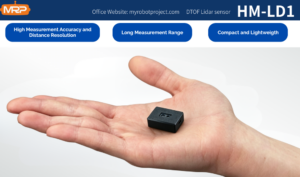
The DTOF Solid State LiDAR HM-LD1 is a compact SPAD dToF LiDAR module designed to provide real-time depth images and 3D point cloud data for robotic and UAV perception. Its 28 g weight, 1.2 W power consumption, 60° × 45° field of view, and UART / UDP / UVC interface support make it suitable for drone automatic avoidance, UAV altitude hold, terrain following, autonomous navigation, distance detection, and robotic vision development.
HM-LD1 supports 0.5–25 m ranging indoors and 0.2–8 m ranging in outdoor daytime environments. That makes it a practical fit for compact UAVs working in close-range inspection, indoor navigation, terrain awareness, and controlled autonomy scenarios. The module can be integrated with PCs, Raspberry Pi, companion-computer pipelines, and embedded platforms. MRP also offers SDK support for x86 Windows, x86 Linux, and ARM Linux.
DTOF Solid State LiDAR HM-LD1 product page
Download DTOF SSL HM-LD1 Product Brochure
| Specification | DTOF Solid State LiDAR HM-LD1 | Why It Matters for Drone Automatic Avoidance |
|---|---|---|
| Technology | Solid-state LiDAR based on SPAD dToF technology | Provides direct depth sensing without a bulky rotating LiDAR structure. |
| Dimensions | 43.5 mm × 30 mm × 26.5 mm | Compact size helps simplify mounting on small UAV frames and embedded platforms. |
| Weight | 28 g | Low weight reduces payload burden and helps preserve drone flight time. |
| Indoor Ranging Capability | 0.5–25 m | Useful for warehouse drones, indoor navigation, testing, and autonomous robotics labs. |
| Outdoor Ranging Capability | 0.2–8 m | Suitable for short-to-mid-range outdoor obstacle detection and inspection scenarios. |
| Ranging Accuracy | ±3 cm | Supports more stable obstacle distance estimation, altitude awareness, and approach control. |
| Field of View | 60° horizontal × 45° vertical | Provides a practical sensing window for forward, downward, or angled obstacle detection. |
| Resolution | 40 × 30 | Generates depth data for obstacle-zone detection, point cloud processing, and navigation logic. |
| Frame Rate | 10 fps | Appropriate for low-to-moderate-speed UAV perception and controlled inspection missions. |
| Interfaces | UART / UDP / UVC | Supports integration with embedded controllers, PCs, Raspberry Pi, Jetson, and development platforms. |
| Operating Temperature | -20℃ to 60℃ | Supports deployment across many indoor and outdoor industrial environments. |
| Power Consumption | 1.2 W | Low power consumption is beneficial for battery-powered UAV systems. |
| Output Data | Depth image and 3D point cloud data | Enables obstacle detection, distance measurement, autonomous navigation, and robotic vision development. |
| Development Support | SDKs for x86 Windows, x86 Linux, and ARM Linux | Improves integration flexibility for prototyping and deployment across different compute platforms. |
View Product Details & Pricing ➔
Integration Workflow for UAV Platforms
A successful drone automatic avoidance project starts with a clear integration workflow. The sensor must be mounted, powered, connected, calibrated, and tied into software that can turn depth data into safe flight behavior. Skipping these basics is how a system works on a bench and fails in the air.
Step 1 — Define the Avoidance Direction
⚙️ Decide whether the LiDAR will face forward for frontal collision avoidance, downward for altitude hold and terrain following, sideways for wall tracking, upward for ceiling or bridge work, or multiple directions for broader coverage. One sensor cannot see everywhere, so the mounting plan must match the mission risk.
Step 2 — Confirm Mechanical Mounting
⚙️ Mount the module securely with a clean field of view. Avoid propellers, landing gear, gimbals, frame arms, protective shells, loose cables, and anything else that can block or contaminate the sensor window. Think about vibration, airflow, center of gravity, dirt accumulation, and impact protection.
Step 3 — Select the Data Interface
⚙️ Choose the interface based on the system architecture. UART works well for embedded communication. UDP is useful for networked streaming to a companion computer. UVC can simplify workflows that already process camera-like video streams. HM-LD1’s UART / UDP / UVC support gives developers room to choose the right path.
Step 4 — Connect to Companion Computer or Flight Controller
⚙️ Many UAV autonomy systems use a Raspberry Pi, NVIDIA Jetson, x86 Linux computer, or ARM Linux embedded board as a companion computer. That computer processes depth data and sends commands to the flight controller through MAVLink, ROS, or custom middleware. Direct flight-controller integration may work for simple cases, but advanced perception usually benefits from dedicated compute.
Step 5 — Convert Depth Data into Avoidance Logic
⚙️ The software should capture the depth frame, filter invalid values, segment obstacle zones, estimate nearest obstacle distance, apply safety thresholds, and send the correct action to the flight controller. That action might be brake, hover, climb, descend, reroute, or stop the mission. Good systems also include confidence checks, timeout handling, and failsafe behavior when data is invalid or delayed.
Step 6 — Validate in Controlled Conditions
⚙️ Test static obstacles, moving obstacles, indoor lighting, outdoor sunlight, reflective targets, dark surfaces, thin objects, vibration, maximum safe speed, and failsafe behavior. Do not discover your real operating envelope next to a bridge beam or warehouse rack. Prove it in controlled conditions first.
Application Scenarios for LiDAR-Based Drone Automatic Avoidance
Infrastructure Inspection
✅ Bridge, dam, tunnel, roofline, expressway, and tower inspections often require drones to fly close to structures. LiDAR-based depth sensing helps estimate separation distance and supports safer inspection passes. A compact module is especially useful when the drone also needs to carry cameras, thermal payloads, or other inspection sensors.
Warehouse and Indoor Drone Navigation
✅ Warehouses often have poor GPS reception, repetitive shelves, narrow aisles, and moving equipment. Depth sensing helps with obstacle detection, wall following, local navigation, and docking. The HM-LD1’s 0.5–25 m indoor range makes it relevant for indoor autonomy development and warehouse drone testing.
Terrain Following and Altitude Hold
✅ A downward-facing LiDAR can help a UAV maintain height above terrain, platforms, or uneven ground. This is useful for agricultural drones, inspection vehicles, landing systems, and low-altitude mapping platforms. Local depth data can improve altitude awareness when GPS altitude or barometric readings are not precise enough.
Agricultural UAVs
✅ Agricultural drones may work near trees, poles, greenhouses, irrigation structures, and uneven terrain. LiDAR can support short-range obstacle awareness and terrain-following behavior. Lightweight, low-power sensors are especially valuable because agricultural drones already carry payloads and need endurance.
Security and Patrol Drones
✅ Patrol drones can use automatic avoidance to reduce collision risk during repeat routes. LiDAR helps identify obstacles that were not present during route planning, such as parked vehicles, temporary equipment, open doors, or people moving through a patrol zone.
Research and Development Platforms
✅ HM-LD1 is also a good fit for teams working on ROS perception, SLAM, UAV autonomy, embedded vision, AI navigation, and multi-sensor fusion. Depth images, point cloud data, multiple interfaces, and SDK support help developers build and test perception-to-control workflows before moving toward production deployment.
Common Mistakes When Building Drone Automatic Avoidance
Mistake 1 — Choosing Range Without Considering Flight Speed
A faster drone needs more distance to detect, process, brake, and reroute. Engineers should calculate stopping distance and include latency, command response, payload, wind, and safety margin. A range that works for slow inspection may not work for faster outdoor flight.
Mistake 2 — Assuming One Sensor Covers All Directions
A single forward-facing sensor cannot detect rear, side, upper, or lower obstacles. If the mission includes lateral movement, reverse flight, ceiling work, or terrain following, you may need additional sensors or a different mounting strategy.
Mistake 3 — Ignoring Outdoor Sunlight Performance
Outdoor optical sensing is affected by ambient light. Always compare indoor and outdoor range separately. The HM-LD1 specifies 0.5–25 m indoor ranging and 0.2–8 m outdoor daytime ranging, which should be matched to actual mission speed and lighting conditions.
Mistake 4 — Confusing Point Cloud Output with Flight Avoidance
Point cloud output is useful, but it is not avoidance by itself. Software still needs filtering, obstacle segmentation, safety thresholds, command generation, and failsafe handling. Without that pipeline, the drone may collect good data and still fly into something.
Mistake 5 — Mounting the Sensor Behind Obstructions
Propellers, landing gear, gimbals, cables, housings, and frame parts can block or contaminate the field of view. Even partial obstruction can create false readings or blind zones. Always validate mounting with live depth data while the drone is moving.
Mistake 6 — Skipping Real-World Testing
Bench testing is only the starting point. UAV avoidance must be tested under vibration, motion, lighting changes, different materials, reflective targets, dark surfaces, and real flight speeds. In the shop, we trust measured behavior, not assumptions.
Buyer’s Checklist for Drone Automatic Avoidance LiDAR
Use this checklist to compare LiDAR modules for UAV obstacle detection, terrain following, altitude hold, and autonomous navigation development. The right sensor should match the aircraft, mission environment, software architecture, and safety requirements.
| Question | Why It Matters | HM-LD1 Reference |
|---|---|---|
| Is the module lightweight enough for my UAV? | Weight affects flight time and payload capacity. | 28 g |
| Does it support outdoor obstacle detection? | Sunlight can reduce optical sensing range. | Outdoor: 0.2–8 m |
| Is the FOV wide enough? | FOV determines obstacle coverage area. | 60° × 45° |
| Is the accuracy suitable? | Accurate distance improves control decisions. | ±3 cm |
| Can my processor read the data? | Interface compatibility reduces integration risk. | UART / UDP / UVC |
| Is development support available? | SDKs reduce engineering time. | x86 Windows, x86 Linux, ARM Linux SDKs |
| Can it operate in my temperature range? | Industrial UAVs may work in harsh environments. | -20℃ to 60℃ |
Start Your UAV LiDAR Integration Project
HM-LD1 supports UART, UDP, and UVC interfaces, with SDKs for x86 Windows, x86 Linux, and ARM Linux platforms.
Full LiDAR setups are powerful — but often too heavy, too complex, or just …
FAQ: Drone Automatic Avoidance
How effective is drone automatic avoidance in real-world flying, and is it worth the extra cost?
Why does my drone detect obstacles but still fail to evade them?
What sensor should I use for beginner, DIY, or ArduPilot drone obstacle avoidance projects?
Can LiDAR completely replace cameras on autonomous drones?
What LiDAR range is enough for drone automatic avoidance?
Is field of view more important than detection range?
Can the HM-LD1 be used for outdoor drone obstacle avoidance?
How should a LiDAR sensor be mounted on a drone?
Does a 10 fps LiDAR frame rate work for drone automatic avoidance?
What is the difference between a depth map and a point cloud for UAV avoidance?
📚 References & Further Reading
- Industry Standard: IEEE Photonics Society and STMicroelectronics
- Related Guide: LiDAR scans and accurate 3D data for robots, LiDAR Images Explained: How to Find View, and UAV dToF LiDAR guide