


Obstacle Avoidance Sensors for Robots & Drones: What Really Works Before You Buy
Here’s the deal: obstacle avoidance is no longer a “nice-to-have” feature for robots and drones working in the real world. In warehouses, inspection sites, farms, construction zones, security patrol routes, tunnels, and GPS-denied indoor spaces, unexpected obstacles are part of the job. A drone may run into tree branches, cables, walls, cranes, reflective glass, or uneven terrain. A mobile robot may face pallets, people, forklifts, ramps, low-profile objects, or glossy partitions. Without dependable obstacle detection and good navigation logic, even a high-dollar robot can turn into a downtime machine.
Look, not every obstacle avoidance sensor works the same way. Ultrasonic sensors, stereo cameras, ToF cameras, solid-state LiDAR, mechanical LiDAR, radar, and vision-based AI systems all have their own strengths, weak spots, integration headaches, and environmental limits. In the shop, the question is never just “How far can it see?” The real question is whether the sensor can see the right obstacle, at the right time, in the right conditions, and feed usable data into the control system fast enough to matter.
This guide walks through what actually matters before you buy: sensing range, field of view, frame rate, outdoor performance, depth accuracy, point cloud quality, processing latency, interface support, SDK availability, payload impact, and system-level integration. We’ll also look at a compact solid-state dToF LiDAR module, the DTOF Solid State LiDAR HM-LD1, as a practical example for robots, drones, SLAM, navigation, altitude hold, terrain following, and 3D perception development.
Table of Contents
- 👉 What Is Obstacle Avoidance?
- 👉 Why Obstacle Avoidance Matters for Robots and Drones
- 👉 How Obstacle Avoidance Works
- 👉 Main Types of Obstacle Avoidance Sensors
- 👉 Obstacle Avoidance for Robots vs Drones
- 👉 Key Specs to Check Before You Buy
- 👉 Why dToF Solid-State LiDAR Is Becoming Popular
- 👉 Product Example: DTOF Solid State LiDAR HM-LD1
- 👉 Integration Guide for Engineers
- 👉 Common Failure Modes and Limitations
- 👉 Obstacle Avoidance Sensor Selection Framework
- 👉 Final Takeaway: Choose Obstacle Avoidance as a System
- 👉 Obstacle Avoidance FAQ
What Is Obstacle Avoidance?
Obstacle avoidance is the ability of a robot, drone, AGV, AMR, UAV, or other autonomous machine to detect objects in its operating path and adjust movement to prevent collision. In practical engineering terms, obstacle avoidance is not just a sensor bolted onto a frame. It is a full perception-and-control loop that starts with environmental sensing and ends with a safe motion response.
A complete obstacle avoidance system usually includes sensor hardware, data acquisition, filtering, depth estimation, object detection, local path planning, motion control, and fallback behavior. The sensor may deliver a single distance value, a 2D scan, a depth image, radar returns, camera frames, or a 3D point cloud. The robot then needs software to decide whether to stop, slow down, steer around, hover, climb, descend, re-plan, or trigger an emergency action.
It helps to separate a few terms. Obstacle detection means the system can sense that something exists. Collision warning means it can alert the operator or controller. Collision avoidance means it can take a protective action, often from a simple distance threshold. Intelligent obstacle avoidance adds context, local planning, and smoother decisions. Autonomous navigation goes further by combining obstacle avoidance with mapping, localization, mission logic, and sometimes fleet management.
For a deeper sensor-level explanation, see this guide to choosing a depth sensor for obstacle avoidance.
Why Obstacle Avoidance Matters for Robots and Drones
Reducing Crash Risk and Hardware Loss
Commercial robots and drones often carry payloads that cost more than the base platform. A UAV may carry a mapping camera, thermal camera, inspection gimbal, gas detector, or communications relay. A warehouse AMR may carry inventory, bins, or automation tooling. When avoidance fails, the loss is not only the damaged frame. You can lose mission data, repair labor, production time, customer confidence, and sometimes a safe work zone.
Improving Mission Reliability
Industrial environments do not sit still. A route that is clear at 8 a.m. may have forklifts, workers, carts, ladders, cables, barriers, or construction materials by lunch. Obstacle avoidance gives the machine a way to react to conditions that were not in the original map. This matters for inspection robots, cleaning robots, delivery robots, security robots, and UAVs repeating routes in semi-structured environments.
Supporting Semi-Autonomous and Fully Autonomous Operation
Obstacle avoidance is one of the foundations of autonomy. Altitude hold, terrain following, SLAM support, indoor navigation, zone monitoring, and autonomous inspection all require local perception. In warehouses, tunnels, and indoor industrial sites, obstacle avoidance often works with a GPS-denied navigation solution to maintain localization when GNSS is unavailable.
Reducing Operator Workload
Even with a human in the loop, good obstacle avoidance reduces workload. The operator can supervise the mission instead of constantly correcting the path. For UAVs, that can mean safer low-altitude flight and fewer panic-stick moments. For AMRs, it can mean fewer blocked-route events and smoother travel around dynamic obstacles.
How Obstacle Avoidance Works
Step 1: Sensing the Environment
The pipeline starts with sensing. Ultrasonic sensors measure reflected sound. Infrared sensors measure light reflection. Stereo cameras infer depth from two images. ToF cameras and dToF LiDAR modules measure light travel time. Radar measures radio-frequency reflections. Mechanical LiDAR sensors scan using moving optics. Each method produces different data quality, update rates, blind spots, and failure modes.
Step 2: Creating Distance, Depth, or Point Cloud Data
Raw readings need to become useful spatial information. A basic proximity sensor may output one distance number. A ToF depth camera may output a grid of depth values. A LiDAR module may output both a depth image and a 3D point cloud. For avoidance, that data must be aligned with the robot coordinate frame so the system knows whether an object is ahead, below, beside, or inside a defined safety zone.
Step 3: Filtering Noise and Detecting Obstacles
Real-world sensor data is messy. Sunlight, reflective surfaces, glass, dark materials, multipath reflections, dust, vibration, motion blur, and electrical noise can cause false readings or missing data. Good software filters invalid pixels, outliers, multipath artifacts, and reflective-surface errors before the planner makes a decision.
Step 4: Planning a Safe Path
Once the system identifies an obstacle, the local planner decides what to do. A ground robot may slow down, stop, steer around, reroute, or trigger a warning. A drone may hover, climb, descend, back away, or return to a safer route. The planner must respect braking distance, turning radius, traction, acceleration, payload stability, and mission rules.
Step 5: Sending Commands to the Robot or Flight Controller
The final step is control output. The perception and planning system sends commands to motor controllers, a flight controller, a navigation stack, or a higher-level autonomy system. Range alone is not enough. If a drone flies at 10 m/s and only detects reliable obstacles at 3 m, there may not be enough time to classify the obstacle and maneuver. Engineers need to evaluate range, frame rate, processing time, command latency, braking distance, and safety margin together.
Main Types of Obstacle Avoidance Sensors
Ultrasonic Sensors
Ultrasonic sensors are low-cost, simple, and useful for short-range detection. They work for basic collision warning, simple robotics, parking-style assistance, and close-range presence detection. Their weak spots are low angular resolution, wide beam shape, soft materials, and angled surfaces that reflect sound away from the receiver.
Infrared Distance Sensors
Infrared sensors are compact and inexpensive. They can provide fast short-range proximity detection, but they are sensitive to surface reflectivity and ambient light. Dark, glossy, or outdoor objects can produce inconsistent readings.
Stereo Vision Cameras
Stereo vision uses two cameras to estimate depth from image disparity. It provides rich visual data and works well with AI object recognition. The catch is that depth accuracy depends on lighting, texture, calibration, and baseline distance. Low-texture walls, darkness, glare, and long-range targets can all reduce performance.
Time-of-Flight Depth Cameras
Time-of-flight depth cameras emit light and calculate distance from the reflected signal. They provide direct depth output and are useful for indoor robots, people detection, manipulation, short-range navigation, and robotic perception. Sunlight, multipath, reflectivity, and transparent objects can affect results.
Solid-State LiDAR
Solid-state LiDAR is attractive because it can provide depth or point cloud data without a large rotating mechanism. It is compact, rugged, and suitable for embedded perception. Industrial LiDAR suppliers such as Blickfeld have helped push the market toward compact, scalable LiDAR-based perception systems.
Mechanical Scanning LiDAR
Mechanical scanning LiDAR is mature and widely used for mapping, navigation, autonomous vehicles, and high-end robotics. It can provide wide coverage and strong geometry, but it is typically larger, heavier, more expensive, and mechanically more complex than small solid-state modules.
Radar and Millimeter-Wave Sensors
Radar and mmWave sensors can work in dust, fog, smoke, and poor weather. They are useful for outdoor vehicles and harsh industrial environments. Their spatial resolution is usually lower than LiDAR or cameras, so they are often paired with optical sensors.
Sensor Fusion Systems
Many reliable systems use sensor fusion. A robot may combine LiDAR for geometry, a camera for classification, radar for harsh-weather reliability, IMU data for motion compensation, and wheel odometry for tracking. Fusion helps prevent one weak sensor condition from taking down the whole system.
| Sensor Type | Strengths | Limitations | Best-Fit Applications |
|---|---|---|---|
| Ultrasonic | Low cost, simple integration, useful for short-range detection | Low resolution, wide beam, affected by soft materials and angled surfaces | Basic collision warning, simple robotics, parking assistance |
| Infrared Distance Sensor | Compact, inexpensive, fast response | Limited range, sensitive to reflectivity and ambient light | Short-range proximity detection |
| Stereo Camera | Rich visual data, passive sensing, AI-compatible | Needs texture and lighting; depth accuracy decreases with distance | Visual navigation, object recognition, robotics research |
| ToF Depth Camera | Direct depth output, compact, good for 3D perception | Can be affected by sunlight, multipath, reflectivity | Indoor robots, people detection, manipulation, short/mid-range avoidance |
| Solid-State LiDAR | No rotating mechanism, compact, reliable, produces depth/point cloud data | FOV and range depend on module design | Drones, AMRs, SLAM, inspection robots, embedded perception |
| Mechanical LiDAR | Wide coverage, mature for mapping and navigation | Moving parts, higher cost, larger size, heavier | Autonomous vehicles, mapping, high-end robotics |
| Radar/mmWave | Works in dust, fog, smoke, and some poor-weather conditions | Lower spatial resolution than LiDAR or camera systems | Outdoor robots, vehicles, harsh environments |
Obstacle Avoidance for Robots vs Drones
Ground Robots and AMRs
Ground robots usually care about horizontal coverage, low obstacle detection, people detection, pallet detection, safety zones, and reliable stop-distance calculation. They work around shelves, forklifts, carts, workers, ramps, floor transitions, cables, and temporary objects. Integration with ROS, SLAM, fleet management, and navigation stacks is often important. Sensor placement matters too. A sensor mounted too high may miss low objects; a sensor mounted too low may be blocked by dust, bumpers, or floor reflections.
Drones and UAVs
Drones bring a different set of constraints. Weight, power consumption, vibration, and mounting locations drive the decision. A UAV may need forward-facing obstacle avoidance, downward-facing altitude hold, terrain following, landing assistance, or multi-directional sensing. Outdoor light tolerance matters because drones often fly under bright sun and hard shadows. Flight controller compatibility is critical because avoidance commands must become stable flight behavior.
Shared Requirements
Both robots and drones need reliable range, suitable field of view, manageable latency, filtering, and predictable integration. For drones, sensor weight and power affect flight time directly. A 28 g module with 1.2 W power consumption is much easier to justify than a heavy scanning unit. For robots, power may be less constrained, but enclosure design, cable routing, environmental protection, and software support still matter.
Key Specs to Check Before You Buy
Detection Range
Detection range is usually the first spec buyers check, but it is easy to misunderstand. Optical sensors often have different indoor and outdoor range performance because sunlight adds ambient optical noise. For the HM-LD1, the listed ranging capability is indoor 0.5–25 m and outdoor 0.2–8 m. If your platform works outdoors at speed, evaluate the outdoor range first.
Ranging Accuracy
Ranging accuracy affects clearance, object position estimates, and path planning. HM-LD1 lists ±3 cm ranging accuracy. That is useful, but accuracy should be judged with object size, robot speed, safety margin, mounting alignment, and software filtering.
Field of View
Field of view determines how much area the sensor sees. HM-LD1 provides 60° horizontal by 45° vertical FOV. That is useful for focused forward, downward, or zone-based depth perception, but it is not all-around coverage. If your robot needs 360° awareness, plan for multiple sensors or another architecture.
Resolution
HM-LD1 provides 40 × 30 depth resolution. That can support obstacle presence detection, point cloud generation, and compact embedded perception. Still, engineers should test small objects, thin wires, narrow legs, and low-profile hazards before signing off.
Frame Rate and Latency
HM-LD1 provides 10 fps. That can be suitable for many mobile robots, inspection systems, mapping tasks, and moderate-speed UAV applications. High-speed vehicles may need faster sensing, longer look-ahead distance, larger safety margins, or sensor fusion. Latency includes data transfer, processing, planning, and actuator response.
Interface Options
HM-LD1 supports UART, UDP, and UVC. UART is useful for embedded controllers. UDP fits networked computing. UVC can simplify PC-style video or depth acquisition workflows. Pick the interface that matches the controller, processor, and software stack you actually plan to deploy.
SDK and Platform Support
SDK support saves time. HM-LD1 supports x86 Windows, x86 Linux, and ARM Linux. That is useful for teams prototyping on PCs, Raspberry Pi, embedded Linux platforms, and ARM-based development systems. In real projects, driver maturity can be the difference between a one-week proof of concept and a month of low-level debugging.
Size, Weight, and Power
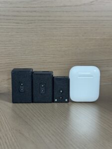
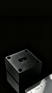
HM-LD1 is listed at 43.5 mm × 30 mm × 26.5 mm, weighs 28 g, and consumes 1.2 W. Those values make it practical for drones, small robots, embedded cameras, and inspection payloads where payload mass, enclosure volume, and thermal budget are tight.
Why dToF Solid-State LiDAR Is Becoming Popular
What dToF Means
dToF means direct time-of-flight. The sensor emits light pulses and measures the time required for reflected light to return. Since the speed of light is known, that delay can be converted into distance. Compared with simple proximity sensing, dToF can generate structured depth information that is much more useful for robot perception, obstacle avoidance, navigation, and mapping.
Why Solid-State Design Matters
Solid-state design removes the need for a large rotating scanner. That can reduce mechanical wear, simplify packaging, improve shock resistance, and make compact integration easier. For drones, this is a big deal. For AMRs and inspection robots, it allows depth sensing to fit into sensor pods, embedded vision housings, and tight industrial enclosures.
SPAD-Based Depth Sensing
SPAD stands for single-photon avalanche diode. SPAD-based receivers can detect very small amounts of returned light, which is useful in compact depth modules. A SPAD dToF system can support real-time depth images and 3D point cloud output, giving robots and UAVs usable geometry instead of a single distance number.
Depth Maps and Point Clouds for Robotics
Depth maps and point clouds matter because they give the perception stack spatial structure. A depth map can identify regions that are too close. A point cloud can be transformed into the robot’s coordinate frame, filtered, clustered, and fused with odometry, IMU, camera, or map data. Outdoor robots may combine avoidance with GNSS correction methods such as RTK positioning, while indoor platforms rely more heavily on visual-inertial navigation, LiDAR, SLAM, and local perception.
Product Example: DTOF Solid State LiDAR HM-LD1
The DTOF Solid State LiDAR HM-LD1 is a compact SPAD dToF LiDAR module designed for real-time depth sensing, point cloud output, robot perception, drone obstacle avoidance, distance detection, autonomous navigation, inspection robotics, and embedded 3D vision development. Its lightweight structure and multiple interface options make it suitable for prototyping and deployment on PCs, Raspberry Pi, flight controllers, and embedded Linux platforms.
HM-LD1 is positioned as a solid-state LiDAR module based on SPAD dToF technology. It delivers real-time depth images and 3D point cloud data for environmental perception. It supports 0.5–25 m ranging in indoor or nighttime conditions and 0.2–8 m ranging in outdoor daytime environments. That makes it relevant for obstacle avoidance, distance detection, autonomous navigation, smart inspection, robotic vision development, UAV altitude hold, terrain following, SLAM support, object recognition, volume measurement, user presence detection, and zone intrusion monitoring.
| Specification | DTOF Solid State LiDAR HM-LD1 |
|---|---|
| Product Name | DTOF Solid State LiDAR HM-LD1 |
| Product URL | View Product Page |
| Technology | Solid-state LiDAR based on SPAD dToF technology |
| Dimension | 43.5 mm × 30 mm × 26.5 mm |
| Ranging Capability | Indoor: 0.5–25 m; Outdoor: 0.2–8 m |
| Ranging Accuracy | ±3 cm |
| Field of View | 60° horizontal × 45° vertical |
| Resolution | 40 × 30 |
| Frame Rate | 10 fps |
| Interface | UART / UDP / UVC |
| Operating Temperature | -20 ℃ to 60 ℃ |
| Power Consumption | 1.2 W |
| Weight | 28 g |
| Output Data | Real-time depth image and 3D point cloud data |
| SDK Support | x86 Windows, x86 Linux, ARM Linux |
| Typical Applications | Obstacle avoidance, robot navigation, SLAM, UAV altitude hold, terrain following, inspection, distance detection, robotic vision development, zone intrusion monitoring |
Download the official brochure: DTOF SSL HM-LD1 Product Brochure
Engineering note: The supplied product content includes a dimensional inconsistency. The specification table lists 43.5 mm × 30 mm × 26.5 mm, while another description mentions 43.5 mm × 43.5 mm × 28.5 mm. For enclosure design, confirm final dimensions against the latest datasheet, brochure, or mechanical drawing before cutting metal or printing housings.
View Product Details & Pricing ➔
Integration Guide for Engineers
Mechanical Integration
Mount the sensor where it has a clean view of the target direction and is protected from unnecessary vibration. Avoid blockage from frames, propellers, bumpers, cables, transparent covers, decorative panels, or payload brackets. The 60° × 45° FOV should be aligned with the actual navigation direction. On drones, forward-facing placement supports forward collision detection; downward-facing placement is better for altitude hold, landing assistance, and terrain following.
Electrical and Power Design
HM-LD1 lists 1.2 W power consumption. Build in stable supply margin, filtering, and grounding. In robots and UAVs, motors, ESCs, switching regulators, and radios can create electrical noise. Keep sensitive signal lines away from high-current power wiring when possible.
Data Interface Selection
Choose the interface based on the system architecture. UART fits embedded controllers and simpler communication. UDP fits networked depth or point cloud transmission. UVC is convenient for PC-style acquisition and early-stage prototyping.
Software and SDK Integration
A practical workflow often starts on a PC for visualization and debugging, then moves to Raspberry Pi, ARM Linux, or another embedded processor for deployment. The software layer should handle acquisition, timestamping, filtering, coordinate transformation, obstacle extraction, safety zone evaluation, and control output.
ROS, SLAM, and Navigation Stack Integration
For robotics projects, the depth image or 3D point cloud can be integrated into ROS, SLAM, or a navigation stack depending on driver availability and data format. Common processing includes point cloud filtering, voxel grids, local costmaps, occupancy mapping, and object clustering. For SLAM, synchronize the sensor with odometry, IMU, wheel encoder, or visual-inertial data where possible.
Testing and Calibration
Test in conditions that match deployment. Include bright sunlight, low light, reflective objects, dark objects, thin obstacles, glass, moving people, dust, mist, vibration, maximum platform speed, and emergency braking distance. Bench testing is useful, but field testing is where the truth shows up.
Common Failure Modes and Limitations
Obstacle Avoidance Is Not the Same as Being Crash-Proof
No obstacle avoidance system is obstacle-proof. A good sensor improves perception, but it cannot guarantee safety in every situation. Performance depends on field of view, range, update rate, reflectivity, lighting, latency, algorithm behavior, speed, braking distance, and installation quality.
Lighting and Outdoor Conditions
Optical systems can be affected by sunlight, glare, shadows, rain, fog, dust, and surface reflectivity. That is why outdoor range must be reviewed separately from indoor range. A sensor that looks great in a lab may have less practical range outside.
Reflective, Transparent, or Absorptive Surfaces
Glass, mirrors, water, glossy metal, black rubber, dark fabric, and steep angled surfaces may create weak or misleading returns. Algorithms should include filtering and fallback logic so one bad reading does not cause unsafe behavior.
Small, Thin, or Fast-Moving Obstacles
Thin wires, cables, branches, chair legs, and fast-moving people can be hard to detect depending on resolution, FOV, frame rate, and distance. Test the smallest obstacle that matters to the mission, not just big boxes and walls.
FOV Blind Spots
A sensor cannot detect what it cannot see. A forward-facing module will not detect obstacles behind the robot. A downward-facing UAV sensor may support terrain following but not frontal avoidance. If all-around avoidance is required, use multiple sensors or a wider-coverage sensor fusion design.
Obstacle Avoidance Sensor Selection Framework
Step 1: Define the Environment
Start by defining where the robot or drone will operate. Indoor warehouses, outdoor construction sites, farms, tunnels, bridges, hospitals, and industrial plants all present different sensing challenges. Include lighting, dust, weather, reflective surfaces, floor conditions, and GNSS availability.
Step 2: Define Vehicle Speed and Stopping Distance
Determine maximum speed, normal speed, braking distance, turning radius, and safety margin. A slow indoor robot has very different requirements from a fast UAV. The sensor must provide enough time for sensing, processing, planning, and control response.
Step 3: Define Obstacle Types
List the expected obstacles: people, pallets, shelves, cables, branches, walls, glass, vehicles, animals, terrain, doors, ramps, machinery, or temporary barriers. Test against realistic targets, including dark, reflective, low-profile, and thin objects.
Step 4: Choose the Sensor Modality
Solid-state dToF LiDAR is attractive for compact robots and UAVs that need direct depth data. Mechanical LiDAR may be better for wide-area mapping. Radar may be needed for harsh outdoor conditions. Cameras may be required for semantic object classification. Many serious systems use more than one modality.
Step 5: Validate Interfaces and SDK Support
Before purchasing, confirm that the sensor connects to your processor, flight controller, network, operating system, and software stack. Interface and SDK support can save major engineering time. For teams tracking the market, this resource on latest LiDAR news and technology updates can help compare sensor architectures and direction.
Step 6: Prototype Before Production
Prototype the complete perception-control loop before finalizing production. Test with the real mounting position, enclosure, processor, cable layout, software stack, speed, and mission environment. In the shop, that is where paper specs either hold up or fall apart.
| Requirement | Recommended Sensor Priority | Reason |
|---|---|---|
| Compact UAV obstacle avoidance | Solid-state dToF LiDAR or lightweight depth sensor | Low weight, low power, direct depth data |
| Indoor AMR navigation | LiDAR + depth camera + SLAM integration | Requires reliable mapping, obstacle detection, and localization |
| Outdoor inspection robot | LiDAR + radar or sensor fusion | Outdoor lighting and weather may affect optical-only sensing |
| Low-cost proximity detection | Ultrasonic or IR | Simple and inexpensive but limited intelligence |
| AI object classification | RGB camera + depth or LiDAR fusion | Combines semantic recognition with distance measurement |
Final Takeaway: Choose Obstacle Avoidance as a System, Not Just a Sensor
Obstacle avoidance should be selected as a complete perception and control capability, not as one component chosen only by price or maximum range. The right decision depends on field of view, accuracy, frame rate, outdoor range, interface options, SDK support, size, power consumption, environmental reliability, mounting position, and compatibility with the robot or UAV navigation stack.
For teams developing compact robots, UAVs, inspection platforms, or embedded 3D perception systems, the DTOF Solid State LiDAR HM-LD1 offers a lightweight dToF LiDAR option with real-time depth image and point cloud output, 0.5–25 m indoor ranging, 0.2–8 m outdoor ranging, ±3 cm accuracy, 60° × 45° FOV, UART/UDP/UVC interfaces, and SDK support across Windows, Linux, and ARM Linux platforms.
Planning a Robot or UAV Perception System?
Contact MyRobotProject to discuss obstacle avoidance, depth sensing, navigation, and positioning modules for your application.
Sharing a compact dToF sensor we’ve been working with for drone obstacle av…
Obstacle Avoidance FAQ
Is obstacle avoidance really worth the extra cost for robots or drones?
What is the difference between intelligent obstacle avoidance and basic collision avoidance?
Does obstacle avoidance make a robot or drone completely crash-proof?
What is the best sensor for obstacle avoidance?
How much range does an obstacle avoidance sensor need?
Is LiDAR better than a camera for obstacle avoidance?
Can obstacle avoidance work outdoors in bright sunlight?
What field of view is good for obstacle avoidance?
What frame rate is needed for obstacle avoidance?
Can obstacle avoidance sensors support SLAM?
📚 References & Further Reading
- Industry Standard: Blickfeld
- Related Guide: Depth Sensor for Obstacle Avoidance






