

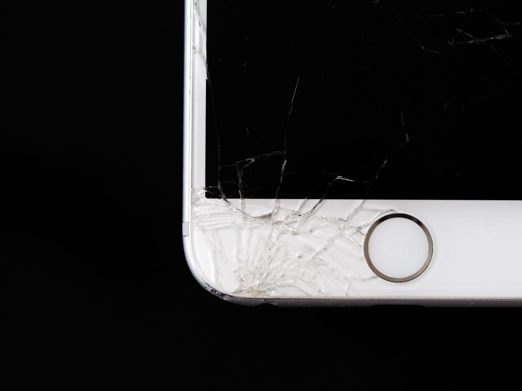
Phone Camera LiDAR Damage: Can Automotive LiDAR Really Burn Smartphone Sensors?
Here’s the deal: the reports are not just internet noise. A growing number of smartphone users have noticed strange dots, streaks, flashing bands, or permanent-looking marks after filming LiDAR-equipped vehicles such as autonomous taxis, advanced driver-assistance test cars, and premium EVs with roof-mounted laser sensors. The question sounds odd at first, but it is fair: can an invisible automotive LiDAR beam really cause phone camera lidar damage? Yes, it can under the wrong conditions. The more useful answer depends on wavelength, pulse energy, distance, exposure time, optical filtering, sensor design, and whether the LiDAR is a long-range automotive unit or a compact robotics depth sensor.
Look, this is not only a consumer-phone curiosity. For robotics developers, drone engineers, smart-city integrators, security-system designers, inspection teams, and industrial buyers, the issue points to a bigger engineering problem: active optical sensors must be used responsibly around cameras, humans, vehicles, and embedded vision systems. This guide explains why some LiDAR systems create visible artifacts or rare sensor damage, how smartphone CMOS sensors react to near-infrared laser pulses, why automotive LiDAR is different from compact dToF modules, and how products such as the DTOF Solid State LiDAR HM-LD1 fit into robotics, UAV, inspection, and development environments.
In the shop, nobody treats a laser emitter like a decorative light. A LiDAR module may be eye-safe under the right classification and still produce ugly artifacts on a camera sensor when the geometry is bad. A phone camera is not a human eye. It has a lens stack, IR filter, microlenses, silicon pixels, automatic exposure, and video processing that can respond to invisible near-infrared pulses in surprising ways. That is why a user may see nothing with the naked eye while the phone records bright flashing streaks.
The practical rule is simple: temporary bands and dots are common; permanent sensor marks are less common but technically plausible. The highest-risk setup is a close phone camera pointed straight into an active high-power LiDAR aperture, especially with zoom or repeated filming. The safer setup is off-axis filming from a reasonable distance while showing the LiDAR’s depth map, point cloud, or application output instead of staring into the transmitter.
Table of Contents
- 👉 Quick Answer: Can LiDAR Damage a Phone Camera?
- 👉 Why People Notice Spots, Lines, and Flashing Artifacts
- 👉 How Automotive and dToF LiDAR Work
- 👉 How Phone Camera Sensors Can Be Affected
- 👉 Main Risk Factors: Power, Distance, Wavelength, and Exposure
- 👉 Automotive LiDAR vs Robotics LiDAR Modules
- 👉 DTOF Solid State LiDAR HM-LD1 Specs and Applications
- 👉 Safe LiDAR Integration for Robots, UAVs, and Vision Systems
- 👉 Camera-Safety and System-Testing Checklist
- 👉 FAQ: Phone Camera LiDAR Damage
Quick Answer: Can LiDAR Damage a Phone Camera?
Yes, LiDAR can damage a phone camera sensor in specific unfavorable conditions. No, that does not mean every LiDAR-equipped vehicle or device is a camera killer. Most visible effects people notice while filming are temporary artifacts caused by pulsed infrared light interacting with a rolling-shutter camera. These artifacts can show up as flashing bands, bright dots, moving lines, purple streaks, white streaks, or odd flicker in video. Once the camera is no longer pointed at the LiDAR source, many of those effects disappear immediately.
Permanent damage is a different matter. It usually takes a rough combination of direct line-of-sight exposure, short distance, concentrated optical energy, repeated or prolonged filming, weak infrared filtering, and sensor-level overload. A quick video from across the street is much less concerning than holding a phone close to an active LiDAR window and filming directly into the emitter. The closer the camera is to the optical output, and the more directly it is aligned with the beam path, the higher the risk.
It helps to separate temporary artifacts from actual sensor damage. Temporary artifacts are visible only during filming and usually come from the camera sampling pulsed light at a different timing pattern than the LiDAR emits it. Stuck pixels are individual pixels that remain bright or colored after exposure. Burned pixels point toward localized physical or electrical degradation. Persistent vertical or horizontal lines may suggest a sensor column, row, or readout path has been affected. These outcomes are uncommon, but they are possible when high-intensity infrared energy is focused into a small sensor area.
Automotive LiDAR systems are normally designed around human eye-safety standards, but eye-safe does not automatically mean camera-proof. Human eyes, phone lenses, CMOS sensors, IR filters, and sensor readout circuits do not behave the same way. Long-range automotive perception systems from companies in the automotive LiDAR ecosystem are built for sunlight rejection, road-speed perception, and long-distance detection. Compact robotics modules are usually built for lower power, shorter range, embedded integration, and controlled operating environments.
Why People Notice Spots, Lines, and Flashing Artifacts
Smartphone Cameras Can See Some Near-Infrared Light
Human eyes cannot see near-infrared light, but silicon CMOS image sensors can respond to part of the near-infrared spectrum. That is why a phone camera may show light from an infrared remote control, facial-recognition emitter, night-vision illuminator, or active LiDAR source even when a person standing nearby sees nothing. Smartphone makers use IR-cut filters to keep normal photos from looking color-shifted, but those filters reduce infrared transmission rather than blocking every photon. Strong infrared pulses can still leak through and register on the sensor.
When near-infrared LiDAR energy reaches a phone camera, the image-processing pipeline has to make sense of light it was never really meant to display. The result can look like purple dots, white flashes, pink streaks, or bright bands. Those colors do not mean the laser is actually purple or white. They come from the sensor response, filter stack, demosaicing algorithm, exposure control, and video processing. That is why two phones can record the same LiDAR source differently, and why one lens on a phone may show the effect more strongly than another.
Rolling Shutter Makes Pulsed Light Look Strange
Most smartphone cameras use rolling shutters. In plain terms, the sensor exposes rows of pixels sequentially instead of capturing the whole frame at one instant. LiDAR systems often emit short pulses or scanning patterns at high speed. When the camera’s row-by-row exposure timing crosses the LiDAR pulse timing, only certain rows receive infrared energy during a frame. The result can be horizontal bands, moving stripes, bright scan lines, flickering dots, broken streaks, or repeating flashes across frames.
Rolling-shutter artifacts can look alarming because they are sharp, bright, and sometimes intense. In many cases, though, they are not permanent damage. They are a timing fight between two active optical systems. Still, if the LiDAR source is powerful, close, and directly aligned with the phone camera, the same energy creating the artifact may also stress the sensor. Treat visible close-range artifacts as a warning sign, not as proof of damage, but not as something to ignore either.
Why Vehicle LiDAR Looks More Intense on Video
Automotive LiDAR is designed for long-range perception. A vehicle moving at speed needs to detect pedestrians, cars, road edges, cyclists, barriers, and unexpected obstacles far enough ahead for the perception and control stack to react. It also needs to operate in sunlight, rain, heat, cold, vibration, and messy road environments. Compared with short-range indoor sensing modules, automotive LiDAR may use stronger optical pulses, larger apertures, sophisticated scanning, and advanced receiver processing.
If a smartphone is pointed directly toward a vehicle LiDAR transmitter aperture, the camera may receive concentrated optical energy rather than weak reflected light. There is a big difference between filming a LiDAR-equipped vehicle from a safe offset angle and filming straight into the active transmitter window. This is why videos of LiDAR-equipped vehicles sometimes show intense dots or lines. The phone is not merely seeing the car; it may be catching active infrared output from the sensor itself.
Temporary Artifact vs Permanent Sensor Damage
| Symptom | Likely Cause | Permanent? |
|---|---|---|
| Flashing bands in video only | Rolling shutter interacting with pulsed IR light | Usually no |
| Bright dots while filming | IR leakage through camera filter | Usually no |
| Fixed white or colored pixels afterward | Possible pixel-level sensor damage | Possibly yes |
| Persistent vertical or horizontal line | Sensor column/row overload or readout artifact | Possibly yes |
The best field test is simple: see whether the mark remains after the phone is no longer aimed at the LiDAR source. If dots, bands, or streaks appear only in the original video, they were probably temporary optical artifacts. If identical marks show up later in normal photos of a white wall, gray sky, or dark background, a sensor-level issue is more likely. Users should also compare the main, ultrawide, and telephoto cameras because modern phones contain multiple independent camera modules.
How Automotive and dToF LiDAR Work
The Basic Time-of-Flight Principle
LiDAR stands for light detection and ranging. A LiDAR system emits light, usually from a laser or laser diode, and measures how long reflected photons take to return after bouncing off an object. Because the speed of light is known, the system calculates distance from the measured time delay. The measured timing includes the outbound trip and the return trip, so the distance calculation divides that travel time by two.
In practical industrial terms, LiDAR gives a machine a fast distance measurement without physically touching the object. That can become a distance reading, a depth map, or a 3D point cloud. In robotics and autonomous systems, that spatial data helps machines detect obstacles, map environments, follow terrain, estimate volume, monitor zones, support navigation, and make better decisions around people and equipment.
What dToF Means
dToF means direct Time-of-Flight. In a direct Time-of-Flight system, the sensor measures the actual travel time of photons instead of estimating distance from phase shift. That is useful when a system needs real-time depth measurements and point-cloud data. A dToF LiDAR module emits controlled pulses, detects returning photons, and converts timing information into distance values across a field of view.
For embedded robotics, dToF is attractive because it gives developers compact distance sensing without relying only on stereo vision, structured light, or ultrasonic sensing. The design can support obstacle avoidance, robot navigation, UAV altitude hold, smart inspection, and machine perception. A compact dToF LiDAR module is usually selected not only for range, but also for weight, field of view, frame rate, interface compatibility, SDK support, and power consumption.
SPAD Sensors and Photon Detection
SPAD stands for Single-Photon Avalanche Diode. A SPAD detector is designed to respond to extremely small amounts of light, even down to individual photon events under the right conditions. In a dToF LiDAR system, SPAD-based sensing helps detect weak reflected signals from objects at distance. Because the return signal can be faint, the system has to combine sensitive photon detection with timing electronics, filtering, and signal processing.
SPAD dToF technology matters for compact solid-state LiDAR because it enables practical depth sensing without large rotating assemblies. Instead of spinning a big sensor head, a solid-state module can provide depth images and point-cloud output in a smaller package. That makes it useful for drones, autonomous mobile robots, inspection equipment, security devices, and embedded vision prototypes where size, weight, and power are real constraints.
Automotive LiDAR System Architecture
An automotive LiDAR system may include a laser emitter, beam-shaping optics, scanner or solid-state beam steering, receiver optics, detector array, signal-processing ASIC, calibration logic, object detection software, and integration with a vehicle perception stack. Its job is not just measuring one distance. It must understand a dynamic road scene, reject sunlight and noise, detect objects at speed, and feed reliable data into advanced driver-assistance or autonomous-driving functions.
That demanding job explains why automotive LiDAR can differ so much from compact robotics LiDAR. Long-range vehicle perception requires strong environmental performance, tight calibration, robust optics, and carefully engineered output. Suppliers in the broader automotive LiDAR technology field focus on vehicle-grade perception, safety, and scale. Their system architecture and optical profile may be very different from a lightweight embedded sensor designed for robot obstacle avoidance or UAV altitude measurement.
Robotics and Embedded LiDAR System Architecture
Robotics and embedded LiDAR modules usually prioritize compact size, low weight, moderate range, lower power consumption, simple digital interfaces, and easy access to depth data. Instead of supporting a complete vehicle perception stack, they may output point clouds, depth maps, or distance measurements over UART, UDP, UVC, or similar integration channels. Developers choose these modules because they can connect to PCs, Raspberry Pi platforms, embedded Linux boards, flight controllers, and industrial controllers with less integration overhead.
In these applications, LiDAR is one sensor in a larger machine. A robot may also use RGB cameras, stereo cameras, IMUs, wheel encoders, GNSS, radar, ultrasonic sensors, or thermal cameras. The engineering challenge is to integrate those sensors without causing interference, blind spots, timing conflicts, reflections, or unnecessary optical exposure. Good system design treats LiDAR as an active optical subsystem, not just another digital peripheral.
How Phone Camera Sensors Can Be Affected
CMOS Pixels Are Light-Sensitive Semiconductor Devices
Smartphone cameras use CMOS image sensors. Each pixel converts incoming photons into electrical charge. Under normal lighting, the sensor, lens, filter stack, and image processor work together to create a photo or video frame. When incoming light exceeds the design tolerance of a pixel or nearby readout circuit, the result may be saturation, blooming, abnormal color response, temporary overload, stuck pixels, or permanent degradation.
Laser light is more challenging than ordinary ambient light because it may be concentrated spatially, temporally, or spectrally. A short pulse can have high peak intensity even when average power looks modest on paper. If that pulse is focused by the phone lens onto a small sensor region, the localized energy density can become significant. That is the core reason automotive LiDAR camera sensor damage is technically possible under bad geometry and exposure conditions.
Why Infrared Light Can Still Reach the Sensor
Consumer cameras are designed primarily for visible-light imaging, but silicon sensors can respond to near-infrared wavelengths. Manufacturers use IR-cut filters to keep colors natural, yet no practical consumer filter blocks all infrared energy under every condition. Some wavelengths pass through partially, especially when the source is strong. The camera may not display that infrared energy accurately, but the sensor can still absorb it.
This is why infrared LiDAR phone camera artifacts can appear even when the user sees nothing directly. The human eye is not the measurement instrument in this case; the CMOS sensor is. Different phones have different IR-cut filters, lens coatings, sensor sensitivities, and image-processing pipelines. That variability explains why two people standing in the same spot can record different LiDAR artifacts from the same vehicle or device.
Thermal and Electrical Overload
There are two broad mechanisms to watch: photonic or electrical overload, and localized heating. Photonic or electrical overload occurs when too many photons create abnormal charge accumulation in a pixel or readout path. The pixel may saturate during exposure, appear as a bright spot, or create a readout artifact. If the stress is high enough, the pixel may not return to normal behavior.
Localized heating is another concern. Concentrated optical energy can raise the temperature of a tiny area on the sensor or filter stack. Semiconductor devices are sensitive to heat, and damage thresholds depend on duration, intensity, wavelength, focusing, and material properties. In ordinary filming scenarios, the exposure is usually not severe enough to cause permanent damage. Close-range direct exposure into a powerful active emitter is the scenario engineers should avoid during demonstrations and testing.
Why Eye-Safe Does Not Always Mean Camera-Safe
Human eye safety standards are designed around biological tissue exposure limits. They account for wavelength, optical power, exposure duration, aperture, retinal focusing, blink response, and tissue absorption. Camera sensors are not biological eyes. They have different lenses, filters, pixel sizes, semiconductor materials, microlenses, and thermal behavior. A system designed to comply with applicable human eye-safety requirements may still create visible artifacts in a phone camera.
This matters for developers and buyers. “Eye-safe” should not be casually translated into “impossible to affect any imaging sensor.” Camera-safe operation depends on the actual camera, distance, angle, optical filtering, exposure time, and LiDAR output characteristics. In robotics and UAV integration, engineers should test nearby cameras directly instead of assuming the eye-safety classification answers every sensor-interference question.
Why Telephoto and Zoom Lenses May Increase Risk
Digital zoom simply crops and enlarges the existing image, so it does not increase the optical energy reaching the sensor. Optical zoom or a dedicated telephoto module is different. A telephoto lens may collect and focus light differently, potentially concentrating energy onto a smaller sensor area or making a distant emitter occupy a larger part of the image. Many phones automatically switch lenses during zoom, so users may not know which camera module is active.
From a practical safety standpoint, users should avoid zooming in on active LiDAR apertures at close range. Engineers should also avoid using consumer phones as close-up optical inspection tools for active infrared emitters. If optical behavior must be evaluated, use proper lab instruments, controlled distances, test targets, neutral-density filtering where appropriate, and sacrificial or lab-grade imaging equipment.
Main Risk Factors: Power, Distance, Wavelength, and Exposure
Optical Output Power and Pulse Energy
LiDAR risk is not determined by one number on a datasheet. Average power matters, but so do peak pulse power, pulse width, repetition rate, beam divergence, aperture size, scan pattern, and optical focusing. A short, intense pulse can saturate pixels even if average power appears moderate. A wide, highly divergent beam may be less concentrated at a given distance than a narrow beam aligned directly into a camera lens.
For engineers evaluating CMOS sensor LiDAR damage risk, the question is not simply whether a LiDAR is “powerful” or “low power.” The real question is how much optical energy can reach a specific camera sensor area under a specific operating geometry and exposure duration. That requires real specifications, measurement data, safety documentation, and intended use conditions.
Distance from the LiDAR Emitter
Distance is one of the biggest practical risk factors. When a beam diverges, energy spreads over a larger area as distance increases. A phone filming from several meters away is usually less exposed than a phone held right near the transmitter aperture. Close-range direct filming is the most important avoidable risk because the camera may receive concentrated optical energy before the beam spreads much.
In product demonstrations, bench testing, or public filming, the safest habit is straightforward: do not place the camera directly in front of the active emitter at close range. Use off-axis views, film the housing rather than the transmitter window, and show depth-map or point-cloud output on a screen. These habits reduce unnecessary exposure while still showing what the sensor does.
Wavelength
Common LiDAR wavelength bands include 850 nm, 905 nm, 940 nm, and 1550 nm. Smartphone camera sensors are generally more sensitive to some near-infrared wavelengths than others because silicon response changes with wavelength and because filter transmission differs across camera models. Near-infrared light around common consumer and industrial bands may leak through IR-cut filters strongly enough to create visible artifacts.
At 1550 nm, silicon sensors respond differently because silicon sensitivity falls off at longer wavelengths. Even so, system-level risk still depends on optics, power, filters, and detector materials. Wavelength alone does not settle the issue. A responsible evaluation considers wavelength together with beam geometry, pulse energy, aperture alignment, camera optics, exposure time, and operating environment.
Exposure Time
A brief incidental recording is lower risk than repeatedly pointing a phone directly at the transmitter. Damage probability rises with repeated exposure, especially at close range. Even if each exposure is short, repeated attempts to capture the “bright LiDAR effect” can increase cumulative stress on the sensor. This matters when people intentionally film autonomous vehicles or test benches to demonstrate LiDAR artifacts.
For labs and integration teams, exposure time should be part of the standard operating procedure. Engineers should define safe viewing practices, avoid unnecessary close-up filming, and use proper measurement equipment when optical behavior must be documented. In customer demos, showing processed point-cloud data is usually better than showing the emitter directly.
Beam Direction and Aperture Alignment
The highest-risk geometry occurs when the camera is aligned with the outgoing beam or scanning aperture. Off-axis observation usually receives less direct energy. Reflective surfaces can complicate the picture because mirrors, glass, polished metal, wet surfaces, or retroreflective materials may redirect light into unexpected paths. For mobile robots, UAVs, and vehicles, enclosure design and mounting angle can reduce direct emitter-to-camera alignment.
Developers should think about onboard cameras and external cameras. An onboard RGB camera mounted near a LiDAR may experience artifacts if the optical paths are poorly arranged. A security camera, phone camera, or machine-vision camera in the environment may also be exposed during testing. Good mechanical design, baffling, mounting geometry, and field validation reduce these problems.
Phone Camera Design Differences
Different phones use different sensors, lenses, IR-cut filters, aperture sizes, telephoto modules, exposure algorithms, and image-processing pipelines. That is why two users can film the same LiDAR source and get different results. One phone might show dramatic flashing bands, while another shows faint dots. One lens module might be affected while another is not. Newer phones may also switch automatically between cameras depending on zoom level, focus distance, and lighting.
| Risk Factor | Lower-Risk Condition | Higher-Risk Condition |
|---|---|---|
| Distance | Several meters away | Very close to emitter aperture |
| Angle | Off-axis filming | Direct line-of-sight into transmitter |
| Exposure Time | Brief incidental recording | Repeated close-range filming |
| LiDAR Type | Compact short-range module | High-power long-range automotive unit |
| Camera Optics | Wide camera, strong IR filtering | Telephoto optics, weaker IR filtering |
Automotive LiDAR vs Robotics LiDAR Modules
Automotive LiDAR Prioritizes Long-Range Perception
Automotive LiDAR is designed to support vehicle perception at speed. It may need to detect cars, pedestrians, cyclists, road barriers, lane-edge objects, and unexpected obstacles at meaningful distances. It must perform under bright sunlight, nighttime conditions, temperature swings, vibration, and motion. The data may be used by advanced driver-assistance systems or autonomous-driving software, so reliability and environmental robustness are central design goals.
This use case can require a different optical architecture than a small embedded module. Long-range automotive systems may use larger optics, higher-performance emitters, more complex scanning, and advanced signal processing. That does not mean every automotive LiDAR will damage a phone camera, but it does mean automotive LiDAR should not be treated like a low-power indoor depth sensor.
Robotics LiDAR Prioritizes Compact Integration
Robotics and UAV LiDAR modules usually prioritize low weight, compact dimensions, low power consumption, short-to-medium range, simple digital interfaces, SDK availability, real-time depth maps, and easy mounting into embedded systems. A drone needs lightweight sensing because every gram affects flight time and payload. An autonomous mobile robot may need a compact field-of-view sensor that fits inside a protective housing. A security or inspection device may need reliable distance sensing without complex vehicle-grade perception hardware.
For these applications, a compact solid-state LiDAR for robots can provide the right balance of depth perception and integration simplicity. Developers often prefer modules with UART, UDP, or UVC output because they reduce software and hardware friction. SDK availability across Windows, Linux, and ARM Linux can also speed up prototyping and deployment.
Why “LiDAR” Is Not One Single Risk Category
“LiDAR” describes a measurement principle, not one hardware design. A roof-mounted automotive LiDAR, an iPhone facial-recognition emitter, an indoor robot depth sensor, an industrial scanner, and a compact dToF module are all different optical systems. They may vary by wavelength, pulse pattern, beam spread, optical power, enclosure design, safety certification, and intended operating distance.
This matters for engineering buyers and searchers trying to understand LiDAR burn smartphone sensor risk. A headline about one vehicle or one laser event does not automatically apply to every LiDAR module. Risk assessment must be based on real specifications and use cases. A long-range vehicle sensor should be evaluated differently from a compact embedded module intended for robotics, UAV altitude sensing, or smart inspection.
Practical Selection Guidance for Developers
Developers should start with application requirements instead of chasing maximum range. Key selection factors include required range, field of view, resolution, frame rate, weight, power budget, interface compatibility, SDK and platform support, operating temperature, integration documentation, and safety procedures. Over-specifying a long-range emitter for a short-range robot can increase cost, complexity, and integration risk without improving system performance.
For many embedded systems, the right answer is a compact module designed for the target range and environment. The DTOF Solid State LiDAR HM-LD1 is positioned for robotics, UAVs, cameras, security systems, smart inspection, and embedded development, rather than long-range automotive roof-mounted perception. Automotive LiDAR expertise from companies such as Innoviz Technologies remains important to the broader industry, but product selection should always match the operating scenario.
DTOF Solid State LiDAR HM-LD1 Specs and Applications
The DTOF Solid State LiDAR HM-LD1 is a compact SPAD dToF LiDAR module designed for real-time depth images and 3D point-cloud data. It supports indoor and nighttime ranging up to 25 m and outdoor daytime ranging up to 8 m, making it suitable for obstacle avoidance, autonomous navigation, UAV altitude sensing, robot perception, zone monitoring, object recognition, volume measurement, user presence detection, camera-assisted autofocus systems, and smart inspection projects. With UART, UDP, and UVC interfaces, it can be integrated with PCs, Raspberry Pi platforms, flight controllers, and embedded Linux systems.
| Specification | DTOF Solid State LiDAR HM-LD1 |
|---|---|
| Product Name | DTOF Solid State LiDAR HM-LD1 |
| Technology | SPAD dToF solid-state LiDAR |
| Dimensions | 43.5 mm × 30 mm × 26.5 mm |
| Weight | 28 g |
| Indoor Ranging Capability | 0.5–25 m |
| Outdoor Ranging Capability | 0.2–8 m |
| Ranging Accuracy | ±3 cm |
| Field of View | 60° horizontal × 45° vertical |
| Resolution | 40 × 30 |
| Frame Rate | 10 fps |
| Interfaces | UART / UDP / UVC |
| Operating Temperature | -20 ℃ to 60 ℃ |
| Power Consumption | 1.2 W |
| Supported Development Platforms | x86 Windows, x86 Linux, ARM Linux SDKs |
| Product Page | View DTOF Solid State LiDAR HM-LD1 |
| Brochure | Download DTOF SSL HM-LD1 Product Brochure |
View Product Details & Pricing ➔
Where HM-LD1 Fits Best
HM-LD1 fits best in systems that need compact 3D sensing without the size, cost, or integration burden of a long-range automotive perception unit. Typical applications include UAV altitude hold, terrain following, robot obstacle avoidance, robot navigation, SLAM assistance, smart inspection, bridge and expressway distance measurement, dam inspection support, security zone intrusion monitoring, object recognition, volume measurement, user presence detection, and camera-assisted autofocus systems.
The module’s indoor ranging capability of 0.5–25 m and outdoor daytime ranging capability of 0.2–8 m make it practical for short-to-medium range sensing. Its ±3 cm ranging accuracy supports precise distance detection in many robotics and inspection workflows. The 60° horizontal by 45° vertical field of view provides area depth perception rather than a single narrow distance point, while the 40 × 30 resolution and 10 fps frame rate support real-time depth-map and point-cloud use cases.
Why Compact dToF Matters for Embedded Systems
Embedded developers often work inside tight limits. A UAV has limited payload and power. A mobile robot has limited mounting space. A smart inspection device may need to operate reliably in a compact enclosure. HM-LD1 addresses those constraints with a 43.5 mm × 30 mm × 26.5 mm body, 28 g weight, and 1.2 W power consumption. Those specifications are especially useful for battery-powered platforms where weight and thermal design directly affect operating time.
Integration flexibility is another strength. UART, UDP, and UVC interfaces make the module adaptable to different development architectures. SDK support for x86 Windows, x86 Linux, and ARM Linux helps teams move from prototype to deployment across PCs, embedded boards, and robotics platforms. For teams building camera-adjacent systems, HM-LD1 should still be mounted and tested responsibly, but its compact dToF profile is fundamentally different from high-power long-range automotive roof LiDAR.
Need compact depth sensing for a robot, UAV, inspection system, or embedded vision project?
Explore the DTOF Solid State LiDAR HM-LD1
or download the technical brochure for integration details.
Safe LiDAR Integration for Robots, UAVs, and Vision Systems
Do Not Aim LiDAR Directly Into Cameras During Close-Range Testing
The most practical safety recommendation is also the simplest: avoid intentionally filming directly into active LiDAR apertures at close range. During bench testing, developers often use smartphones to document prototypes, but a phone is not a calibrated optical safety instrument. If a team needs to show a LiDAR product in a video, it is usually better to film the module housing from an angle and show the depth map, point cloud, or application output separately.
For engineering validation, use off-axis viewing, matte test targets, controlled distances, proper fixtures, and lab-appropriate sensors. If optical output must be recorded, use equipment selected for that job and follow the manufacturer’s safety guidance. These habits reduce the chance of LiDAR spots on phone video, sensor artifacts, or unnecessary camera exposure.
Use Proper Mechanical Mounting and Beam Direction Control
Mechanical design plays a major role in optical safety and integration quality. Enclosure design, mounting angle, aperture shielding, beam path control, and physical baffling can all reduce unnecessary exposure to cameras or reflective surfaces. A LiDAR should be mounted so its active optical path supports the sensing task without pointing directly into user cameras, onboard RGB cameras, or nearby machine-vision sensors.
For robots and UAVs, mounting must also account for vibration, field of view, environmental exposure, maintenance access, and cable routing. A well-designed mechanical layout improves data quality and safety. Poor mounting can create blind spots, reflections, camera artifacts, or inconsistent depth data.
Match LiDAR Power and Range to the Application
A short-range indoor robot does not need the same optical architecture as a long-range automotive perception stack. Selecting a module with appropriate range, field of view, weight, and power consumption reduces unnecessary complexity. It can also simplify software integration, thermal design, enclosure design, and safety validation.
For example, a robot depth sensor used for obstacle avoidance in indoor or semi-outdoor environments may benefit more from compact dToF sensing, SDK support, and digital interface flexibility than from maximum detection range. Engineering teams should specify the sensor around the real use case rather than choosing the highest-power or longest-range option by default.
Validate Around Other Sensors
Robots and UAVs often combine LiDAR with RGB cameras, depth cameras, stereo vision, thermal cameras, IMUs, GNSS, radar, and ultrasonic sensors. Integration testing should check whether LiDAR creates interference, artifacts, exposure shifts, synchronization issues, or reflections in nearby imaging systems. This is especially important when cameras and LiDAR are mounted close together or share overlapping fields of view.
Testing should include indoor, nighttime, outdoor, and high-lux conditions because sensor behavior can change dramatically with ambient light. Teams should record point-cloud quality, depth-map stability, frame rate, ranging accuracy, and camera behavior. If public filming is expected, it is also useful to test several smartphone models at reasonable viewing distances.
Document Safe Operating Practices
Safe operating practices should be documented in product manuals, lab SOPs, field test plans, developer kits, customer integration guides, and UAV deployment checklists. Documentation should state how to mount the module, how to avoid direct close-range camera exposure, how to validate nearby vision sensors, and how to interpret visible artifacts during testing.
Clear documentation protects developers and customers. It also improves product adoption because buyers trust equipment more when optical, electrical, software, and safety considerations are explained together. For B2B buyers, supplier support and integration documentation can be just as important as raw specifications.
Camera-Safety and System-Testing Checklist
- ⚙️ Confirm the LiDAR wavelength, optical output characteristics, and safety classification.
- ⚙️ Avoid direct close-range camera exposure to the active emitter aperture.
- ⚙️ Test camera artifacts using sacrificial or lab-grade sensors before customer demos.
- ⚙️ Evaluate different smartphone models if public filming is expected.
- ⚙️ Check RGB cameras, stereo cameras, and machine-vision cameras for interference.
- ⚙️ Use off-axis observation during bench testing.
- ⚙️ Document minimum recommended viewing distance for development teams.
- ⚙️ Validate performance under indoor, nighttime, outdoor, and high-lux conditions.
- ⚙️ Confirm SDK data output stability over UART, UDP, or UVC interfaces.
- ⚙️ Record point-cloud quality, depth-map stability, frame rate, and ranging accuracy.
Bench Test Workflow
A good bench test starts in a controlled lab environment. Power up the LiDAR according to the manufacturer’s instructions and aim it at a matte, non-reflective target. Confirm that depth data, point-cloud output, frame rate, and ranging accuracy are stable before introducing other cameras into the scene. When cameras are added, place them off-axis first rather than directly in front of the emitter.
Repeat testing at multiple distances and under different lighting conditions. Check whether nearby RGB cameras, stereo cameras, machine-vision cameras, or smartphone cameras show artifacts. Record whether the artifacts appear only during active LiDAR operation or persist afterward. For modules such as HM-LD1, also confirm interface stability over UART, UDP, or UVC and verify that the SDK output remains reliable during extended operation.
Field Test Workflow
Field testing should begin with mounting and enclosure verification. Confirm that the LiDAR is mechanically secure, the aperture is clean, the beam path is appropriate, and nearby cameras are not directly aligned with the active emitter. Run short-duration tests first, then gradually increase duration while monitoring data quality and camera behavior.
After testing, review video footage for artifacts and inspect camera sensors if close exposure occurred. Record safe operating notes for future deployments, including recommended viewing angles, minimum practical camera distances, and observed sensor interactions. This process is especially valuable for robots, UAVs, inspection systems, and security devices that may operate near public cameras or customer-owned smartphones.

FAQ: Phone Camera LiDAR Damage
These phone camera lidar damage FAQs answer the most common questions from smartphone users, robotics developers, UAV engineers, system integrators, and industrial buyers. FAQPage schema can be added in WordPress or a custom CMS if the answers remain visible on the page.
Can filming a LiDAR-equipped car permanently damage a phone camera?
Why do users report Volvo EX90, Waymo, or other vehicle LiDAR systems leaving spots or lines on phone videos?
Does all LiDAR create the same camera-damage risk?
Are LiDAR systems dangerous to human eyes if they can affect cameras?
Why can a phone camera see infrared LiDAR if people cannot?
Is the risk higher when using zoom on a phone camera?
What should I do if I filmed LiDAR and now see dots on my camera?
Can robotics LiDAR damage nearby machine-vision cameras?
How can developers reduce camera-related LiDAR risks during product design?
Is DTOF Solid State LiDAR HM-LD1 suitable for camera-adjacent robotics applications?
What is the safest way to film or demonstrate an active LiDAR device?
📚 References & Further Reading
- Industry Standard: Innoviz Technologies and the automotive LiDAR ecosystem
- Related Guide: DTOF Solid State LiDAR HM-LD1 product specifications and brochure






