

GPS RTK for Robotics, Drones, and Surveying: How to Choose a Cost-Effective Centimeter-Level Positioning Module
Ordinary GPS is fine when you just need to know roughly where a truck, phone, or vehicle is. But here’s the deal: in robotics, UAV mapping, autonomous vehicles, precision agriculture, construction verification, and professional surveying, “roughly” is not good enough. When a robot clips a crop row, a drone map drifts, or a rover cannot return to the same field point twice, the issue is often not the controller, the path planner, or the software logic. The weak link is usually the positioning layer. GPS RTK fixes that gap by adding real-time correction data to satellite positioning, helping embedded systems move from meter-level GPS to centimeter-level positioning when the sky view, correction link, and installation are right.
Look, the most cost-effective GPS RTK setup is not automatically the cheapest receiver on the page. In the shop, the cheaper part can easily become the expensive part if it burns engineering hours on antenna matching, RF cable routing, waterproofing, mounting brackets, EMI troubleshooting, and serial parsing. For robotics and UAVs, a compact integrated module can save a lot of practical integration pain. For surveying and base-rover workflows, a larger integrated survey module may deliver better field stability and more flexible correction output. This guide walks through how GPS RTK works, which specifications actually matter, how to compare module types, and how to choose between compact helical antenna modules and larger multiband survey modules for real industrial work.
Table of Contents
What Is GPS RTK?
GPS RTK stands for Real-Time Kinematic positioning using satellite navigation signals and real-time correction data. In everyday industry language, people say “GPS RTK” because GPS is the familiar term. Technically, most serious industrial RTK receivers are not GPS-only receivers anymore. They are multi-GNSS systems that can receive signals from GPS, BeiDou, GLONASS, Galileo, QZSS, IRNSS, and other satellite constellations depending on the module design.
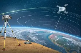
Standard GPS calculates position directly from satellite signals and commonly delivers meter-level accuracy. That works for road navigation, consumer tracking, and approximate asset monitoring. It does not work well when a drone must produce repeatable mapping data, a robot must follow the same outdoor path every day, or a survey device must collect point coordinates with confidence. GPS RTK improves accuracy by using correction data from a base station, correction network, or reference source. The rover receiver uses that correction information to reduce shared satellite, clock, orbit, and atmospheric errors in real time.
GPS RTK vs Multi-GNSS RTK
Although the keyword “gps rtk” is widely used by buyers, engineers should evaluate the full GNSS capability of a module. A modern RTK receiver may support GPS L1/L5, BeiDou B1/B2A/B2I, GLONASS G1, Galileo E1/E5, QZSS L1/L5, and IRNSS L5. More constellations and more frequency bands give the receiver more signals to work with. That can improve satellite availability, strengthen geometry, and help maintain a stable RTK solution in the real world, where part of the sky may be blocked by vehicles, buildings, trees, payloads, or industrial structures.
Why RTK Accuracy Is Written as 1 cm + 1 ppm
RTK accuracy is often specified as a formula such as horizontal 1 cm + 1 ppm and vertical 1.5 cm + 1 ppm. The centimeter value is the base accuracy under suitable conditions. The ppm value means parts per million of the baseline distance. In plain terms, 1 ppm adds about one millimeter of potential error for every kilometer between the rover and the correction reference. That is why short baseline distance, clean sky visibility, stable correction delivery, and high-quality antenna placement all matter. A module specification is important, but field accuracy depends on the entire installation.
For autonomous platforms, positioning is only one layer of the perception stack. If your system also needs obstacle awareness, this guide on drone obstacle avoidance can help you think about how RTK positioning works alongside perception sensors, planning software, and safety logic.
Why Centimeter-Level Positioning Matters in Robotics, Drones, and Surveying
Centimeter-level positioning matters because industrial systems need repeatability, not just approximate location. A consumer GPS receiver may show that a vehicle is in the right field, road, or jobsite. A GPS RTK system can help show where that vehicle is relative to a crop row, survey point, construction boundary, flight path, docking station, inspection route, or machine guidance line. That difference affects productivity, data quality, safety, and rework cost.
Robotics: Repeatable Routes and Autonomous Control
Outdoor robots need reliable positioning for path following, row navigation, inspection routes, docking, perimeter patrol, and autonomous task execution. Agricultural robots may need to travel between rows without damaging crops. Inspection robots may need to revisit the same asset location repeatedly. Delivery robots and autonomous ground vehicles may need lane-level or path-level navigation in outdoor environments. GPS RTK provides a global positioning reference that can be fused with IMU, wheel odometry, LiDAR, camera, or SLAM systems to improve navigation consistency.
Drones: Mapping Accuracy and Flight Stability
UAV mapping, photogrammetry, agriculture, and inspection workflows benefit from precise geotagging and repeatable flight paths. When a drone collects images for mapping, inaccurate location tags can increase processing error or force the crew to use more ground control points. GPS RTK helps improve positioning confidence during flight and can support more accurate field data. For UAV engineers, module size, antenna placement, vibration, EMI exposure, and correction link reliability are all practical concerns. A compact RTK module can reduce payload and integration complexity, while a larger antenna design may fit survey-style UAV systems where reception stability is the priority.
Surveying: Real-Time Field Data Instead of Post-Processing
Surveying workflows often require accurate field point collection, base-rover operation, and immediate coordinate output. Static GPS surveying can deliver high accuracy after long observation and post-processing, but many field teams need real-time decisions. GPS RTK allows survey rovers to output corrected coordinates immediately, reducing the delay between field collection and decision-making. For teams comparing sensor technologies in robotics and mapping stacks, this technical comparison of iToF vs dToF can also provide useful context for perception system planning.
How GPS RTK Works: Base Station, Rover, RTCM, and NMEA
A GPS RTK system has two major information flows. The first is satellite signal reception. The rover receives GNSS signals and calculates position. The second is correction data. The rover receives real-time correction data from a local base station, survey base, NTRIP network, or other reference source. By combining raw satellite measurements with correction data, the receiver can produce a much more precise position than standard GPS alone.
The Rover Side: Receiving GNSS Signals and Corrections
The rover is the moving device. It may be mounted on a robot, drone, survey pole, autonomous vehicle, marine platform, agricultural machine, or mapping system. The rover receives GNSS signals from multiple satellite constellations and receives correction data through a communication link. The correction data may arrive over radio, 4G, Wi-Fi, serial connection, or another system-level data path. The rover then calculates a corrected position and outputs navigation data to the controller, embedded computer, survey device, or software stack.
The Base Side: Generating Correction Data
The base station or reference source is placed at a known or stable position. It receives the same satellite signals as the rover and estimates errors that affect the local environment. Those corrections are transmitted to the rover, commonly using RTCM messages. This correction process helps compensate for satellite clock errors, orbit errors, atmospheric delay, and other shared error sources. Correction latency, baseline distance, communication reliability, and satellite visibility all affect final positioning quality.
NMEA Output and RTCM Input
NMEA 0183 is commonly used for navigation output, while RTCM is commonly used for correction input. A GPS RTK module may output latitude, longitude, altitude, speed, heading, fix status, satellite count, and other navigation information through NMEA sentences. RTCM messages carry correction data that allows the rover to calculate a high-precision solution. For example, the Helical Antenna RTK Module HM-D20 provides NMEA 0183 output and RTCM input at the rover side. The Multiband RTK Survey Module HM-D13 provides NMEA 0183 output and RTCM input at the rover side, and it also supports RTCM output at the base side.
Why Multi-Band Reception Improves Reliability
Multi-band reception improves reliability because the receiver has more signal information to work with. L1 and L5 support can help the receiver manage ionospheric delay and improve positioning stability. Multi-constellation support increases the number of satellites available, which can improve geometry and reduce the risk of losing a fixed solution when some signals are blocked. In practical applications, real environments are not perfect open fields. Robots may operate near trees, buildings, equipment, or metal structures. Drones may experience airframe interference and vibration. Survey rovers may move through mixed visibility conditions. Multi-band, multi-GNSS support helps reduce those risks.
For broader context on industrial perception and autonomy ecosystems, readers can also review established suppliers such as Hesai Technology and positioning/navigation companies such as Bynav Technology.
GPS RTK vs Standard GPS vs Static GPS Surveying
Buyers often compare GPS RTK with normal GPS and static GPS surveying. Each method has a different cost structure, workflow, accuracy level, and best-fit application. The right choice depends on whether you need real-time output, centimeter-level precision, post-processed survey accuracy, or basic location tracking.
| Positioning Method | Typical Accuracy | Real-Time Output | Correction Requirement | Best Use Cases |
|---|---|---|---|---|
| Standard GPS | Meter-level | Yes | No RTK correction required | Consumer navigation, basic tracking, low-precision location |
| GPS RTK | Centimeter-level under suitable conditions | Yes | RTCM correction from base or network | Robotics, drones, surveying, mapping, machine guidance |
| Static GPS Surveying | High accuracy after processing | No, usually post-processed | Longer observation and post-processing | Control points, geodetic work, high-precision survey baselines |
When Standard GPS Is Enough
Standard GPS is enough when approximate position is acceptable. Fleet tracking, low-cost asset monitoring, consumer navigation, and simple location logging may not require RTK. If your system only needs to know which general area a vehicle or device is in, RTK may add unnecessary complexity. Once the task requires repeatable lane-level, row-level, point-level, or machine-control accuracy, standard GPS usually becomes the limiting factor.
When GPS RTK Is the Better Choice
GPS RTK is the better choice when real-time centimeter-level positioning supports the mission. Outdoor robots, UAV mapping platforms, construction guidance systems, agricultural machines, marine positioning systems, and survey rovers all benefit from live corrected coordinates. RTK is especially valuable when field decisions must be made immediately instead of waiting for post-processing.
When Static GPS Surveying Still Makes Sense
Static GPS surveying still makes sense for control points, geodetic networks, and high-precision baselines where long observation time and post-processing are acceptable. It may provide excellent accuracy, but it is not designed for live robot navigation or real-time UAV control. Many professional teams use both approaches depending on workflow requirements.
Key GPS RTK Module Specifications to Compare Before Buying
Choosing a GPS RTK module requires more than comparing price. The total system cost includes mechanical integration, antenna placement, waterproofing, communication setup, correction delivery, software parsing, timing synchronization, and field validation. A low-cost module can become expensive if it creates repeated installation failures or unstable RTK performance.
1. Supported Frequency Bands and Satellite Constellations
Look for multi-band and multi-constellation support. The HM-D20 supports GPS L1/L5, BeiDou B1/B2A/B2I, GLONASS G1, Galileo E1/E5, QZSS L1/L5, and IRNSS L5. The HM-D13 supports GPS L1/L5, BeiDou B1/B2A/B2I, Galileo E1/E5, QZSS L1/L5, GLONASS G1, and IRNSS. These supported signals help improve availability and stability, especially when the receiver has partial sky visibility.
2. RTK Position Accuracy
Both HM-D20 and HM-D13 specify RTK position accuracy of horizontal 1 cm + 1 ppm and vertical 1.5 cm + 1 ppm. This level of accuracy is suitable for many robotics, UAV, surveying, and outdoor industrial positioning applications when the environment, correction link, and installation are properly controlled. Engineers should remember that vertical accuracy is usually more challenging than horizontal accuracy, and real-world performance depends on sky view, multipath, baseline distance, correction age, and fix status.
3. Antenna Design: Helical vs Mushroom Integrated Antenna
A compact helical antenna module can be attractive for embedded robots, UAVs, unmanned vehicles, ships, and smaller positioning systems. It reduces external antenna matching work and simplifies installation. A larger mushroom-shaped integrated GNSS antenna is often better suited for survey poles, base-rover workflows, field vehicles, or outdoor systems where size and weight are less constrained. The best antenna design depends on mounting space, platform vibration, environmental exposure, and reception requirements.
4. Interface and Protocol Support
Both products use a TTL-level UART interface, which is common for flight controllers, embedded computers, microcontrollers, Raspberry Pi systems, Jetson platforms, and custom robotics electronics. NMEA 0183 output allows software to read navigation data, while RTCM input allows the rover to receive corrections. HM-D13 also supports RTCM output at the base side, making it more flexible for base-rover workflows.
5. Baud Rate and Data Throughput
Both HM-D20 and HM-D13 specify a baud rate of 115200 bps. Baud rate matters because RTK systems may transmit multiple positioning messages, satellite information, timing data, and correction streams. Engineers should confirm that the selected message rate, enabled NMEA sentences, and correction workload fit within the communication configuration used by the controller or embedded computer.
6. Timing Synchronization Accuracy
Both modules specify 20 ns timing synchronization accuracy. Timing is important when RTK is part of a larger sensor-fusion system. UAV mapping, camera triggering, LiDAR timestamping, robot navigation logs, and synchronized perception stacks all benefit from accurate timing. Even when the main goal is position, timing quality can affect data alignment and downstream mapping performance.
7. Environmental Protection
Industrial GPS RTK modules often operate outdoors in rain, dust, cold, heat, vibration, and sun exposure. HM-D20 specifies IP67 waterproofing and an operating temperature of -40 ℃ to 85 ℃. HM-D13 also specifies an operating temperature of -40 ℃ to 85 ℃ and is described as windproof and rainproof for outdoor performance. Environmental durability is especially important for agriculture, marine, construction, surveying, and long-duration field deployments.
8. Mechanical Size and Weight
Mechanical constraints can decide the correct module. HM-D20 measures Φ44 × 37 mm, making it suitable for compact platforms. HM-D13 measures Φ152 × 67.9 mm and weighs less than 550 g, which is more appropriate for survey poles, vehicle mounts, field bases, and larger systems. Small UAVs and compact robots often benefit from HM-D20, while surveying and base-rover applications may benefit from HM-D13.
How to Choose a GPS RTK Module by Application
The best GPS RTK module depends on the application environment. The same accuracy specification can behave differently on a compact drone, ground robot, survey pole, marine platform, or agricultural machine. Engineers should select the module by considering mechanical size, antenna form factor, correction workflow, communication interface, environmental exposure, and software integration resources.
For Embedded Robots and Autonomous Ground Vehicles
Compact integrated modules are often the best fit for robots and autonomous ground vehicles when size, mounting simplicity, and UART integration matter. HM-D20 is a natural fit for robots, UAVs, unmanned vehicles, ships, and general positioning systems because it integrates the GNSS module and antenna, provides NMEA 0183 output, accepts RTCM input, uses TTL-level UART, and includes IP67 waterproofing. If your application also involves robot localization and visual-inertial navigation, this related article on RoboBaton Mini vs Intel T265 may help compare positioning approaches.
For Drones and UAV Mapping
UAV applications require careful attention to weight, vibration, EMI, antenna placement, flight controller compatibility, correction routing, and timing. The antenna should have a clear sky view and should be isolated from high-current wiring, motors, radios, and carbon fiber structures when possible. A compact module can reduce integration burden, while a larger survey module may be useful for specialized mapping platforms that prioritize field stability over payload size.
For Surveying and Base-Rover Workflows
Surveying and base-rover workflows often require strong reception, rugged outdoor construction, and flexible correction handling. HM-D13 is well suited for this category because it supports NMEA 0183 output, RTCM input at the rover side, and RTCM output at the base side. Its integrated mushroom-shaped antenna, larger physical design, and optional 4G radio module support make it a practical choice for survey-style field systems, mapping, and base-rover deployments.
For Marine, Agriculture, and Outdoor Industrial Systems
Marine, agricultural, and industrial systems need durability as much as accuracy. Waterproofing, operating temperature, cable routing, vibration, mounting height, and stable correction delivery can determine whether a system works reliably every day. HM-D20 offers compact IP67 protection, while HM-D13 provides outdoor windproof and rainproof design characteristics suitable for field use. For long-term deployments, module selection should also consider supply stability, documentation, technical support, and OEM or ODM customization needs.
For Developers Building Custom Software
Developers should confirm that the module outputs data in formats their software can parse. NMEA data can be integrated into ROS, Python, C++, Raspberry Pi, Jetson, flight controllers, or custom embedded systems. Software should monitor latitude, longitude, altitude, fix quality, satellite count, correction age, and RTK fixed or float status. A system should not treat every coordinate as equally reliable. It should respond differently to standalone GPS, RTK float, and RTK fixed states.
GPS RTK Integration Workflow for Robots, UAVs, and Software Systems
Successful GPS RTK integration requires both hardware discipline and software validation. A high-quality module can still perform poorly if it is mounted under a metal cover, placed beside a noisy motor controller, configured with the wrong baud rate, or supplied with unstable correction data. The workflow below helps reduce integration risk.
Step 1: Choose the Antenna and Mounting Position
⚙️ Mount the antenna where it has the clearest possible sky view. Avoid locations near motors, high-current cables, power converters, large metal structures, radios, and reflective surfaces. For drones, the antenna is often placed on top of the airframe. For robots and vehicles, it should be elevated above the chassis where practical. For survey workflows, phase center consistency is important because the coordinate corresponds to the antenna reference position.
Step 2: Connect UART and Configure Baud Rate
⚙️ Both HM-D20 and HM-D13 use TTL-level UART and 115200 bps communication. Confirm voltage compatibility with the controller, embedded computer, or flight controller. Check grounding, cable length, and electrical noise. Configure the host software to read the correct serial port and parse the enabled data messages. If the system uses many messages or high update rates, verify that the serial link can support the workload.
Step 3: Feed RTCM Corrections to the Rover
⚙️ The rover must receive RTCM correction data to achieve RTK performance. Corrections may come from a local base station, NTRIP network, survey base, radio link, 4G connection, or other communication method. HM-D13 supports an optional 4G radio module, which can simplify correction delivery in some field workflows. The system should monitor correction age and handle correction loss gracefully.
Step 4: Parse NMEA Data
⚙️ NMEA data may include latitude, longitude, altitude, speed, heading, fix quality, number of satellites, and related navigation fields. Parsing this data correctly is essential for robot navigation, UAV mapping, survey collection, or field logging. Developers should validate units, coordinate frames, update rates, timestamps, and fix-status handling before relying on the data for control decisions.
Step 5: Validate Accuracy in the Real Environment
⚙️ Testing should include open-sky validation, repeat point checks, correction latency monitoring, and fixed versus float behavior. A system that works on a bench may behave differently near trees, buildings, vehicles, or industrial equipment. Validation should happen in the environment where the product will actually operate. Engineers should log data and compare performance across different sky visibility and correction conditions.
Step 6: Integrate with Navigation or Mapping Software
⚙️ After reliable serial communication and correction input are confirmed, integrate the position data with navigation, mapping, or control software. Robotics systems may fuse RTK with IMU, wheel odometry, LiDAR, or visual SLAM. UAV systems may use RTK for geotagging, waypoint control, and mapping accuracy. Survey systems may use RTK coordinates for real-time field point collection and base-rover workflows.
Cost-Effective GPS RTK Module Options for Robotics, Drones, and Surveying
The right GPS RTK module depends on the tradeoff between compact integration and maximum field workflow flexibility. HM-D20 is a compact helical antenna RTK module designed for embedded robots, UAVs, unmanned vehicles, ships, and positioning systems. HM-D13 is a larger multiband RTK survey module designed for surveying, mapping, base-rover workflows, UAV navigation, and outdoor field use.
Helical Antenna RTK Module HM-D20
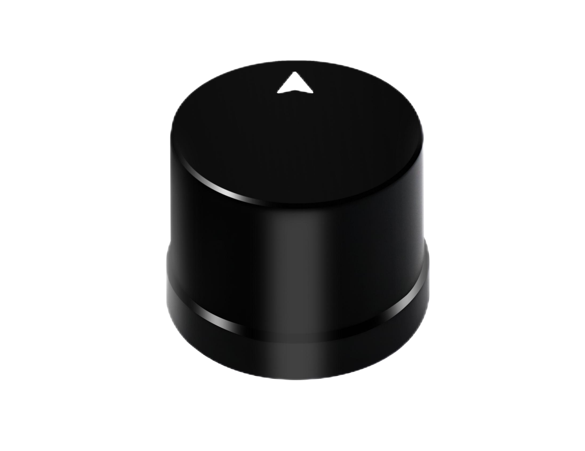
The Helical Antenna RTK Module HM-D20 integrates a GNSS module and antenna in a compact body, allowing users to deploy GPS RTK positioning without an external antenna. It is designed for robots, UAVs, unmanned vehicles, ships, and general positioning systems where compact size, waterproofing, and simplified installation are important. Its L1 and L5 GNSS antenna system provides at least 40 dB high gain, and the rugged housing is designed to resist moisture and harsh weather conditions.
| Frequency Band | GPS L1/L5, BeiDou B1/B2A/B2I, GLONASS G1, Galileo E1/E5, QZSS L1/L5, IRNSS L5 |
| RTK Position Accuracy | H: 1 cm + 1 ppm, V: 1.5 cm + 1 ppm |
| Protocol | NMEA 0183 output and RTCM input at rover side |
| Baud Rate | 115200 bps |
| Dimensions | Φ44 × 37 mm |
| Timing Synchronization Accuracy | 20 ns |
| Antenna System | L1 and L5 GNSS antenna system with at least 40 dB high gain |
| Interface | TTL-level UART interface |
| Operating Temperature | -40 ℃ – 85 ℃ |
| Waterproof | IP67 |
Multiband RTK Survey Module HM-D13
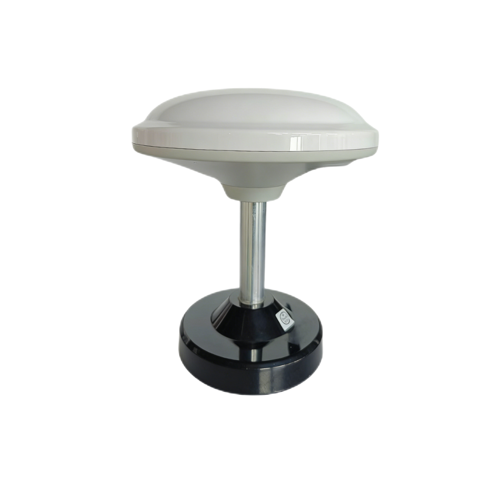
The Multiband RTK Survey Module HM-D13 integrates modules and antennae in an all-in-one structure designed for stable signal reception and precise positioning. It can synchronously receive BDS, GPS, GLONASS, GALILEO, QZSS, and IRNSS satellite signals. Its larger mushroom-shaped integrated antenna design is suitable for surveying, mapping, base-rover workflows, UAV navigation, field vehicles, and outdoor positioning systems. The product is made of UV-resistant PC material and is designed for outdoor windproof and rainproof performance.
| Frequency Band | GPS L1/L5, BeiDou B1/B2A/B2I, Galileo E1/E5, QZSS L1/L5, GLONASS G1, IRNSS |
| RTK Position Accuracy | H: 1 cm + 1 ppm, V: 1.5 cm + 1 ppm |
| Protocol | NMEA 0183 output and RTCM input at rover side. RTCM output at base side. |
| Baud Rate | 115200 bps |
| Dimensions | Φ152 × 67.9 mm |
| Weight | <550 g |
| Interface | TTL-level UART interface |
| Timing Synchronization Accuracy | 20 ns |
| Operating Temperature | -40 ℃ – 85 ℃ |
| Optional Communication | Supports optional 4G radio module |
| Specification | Helical Antenna RTK Module HM-D20 | Multiband RTK Survey Module HM-D13 |
|---|---|---|
| Recommended Use | Robotics, UAVs, unmanned vehicles, ships, compact positioning systems | Surveying, mapping, base-rover workflows, UAV navigation, outdoor field systems |
| Frequency Band | GPS L1/L5, BeiDou B1/B2A/B2I, GLONASS G1, Galileo E1/E5, QZSS L1/L5, IRNSS L5 | GPS L1/L5, BeiDou B1/B2A/B2I, Galileo E1/E5, QZSS L1/L5, GLONASS G1, IRNSS |
| RTK Position Accuracy | H: 1 cm + 1 ppm, V: 1.5 cm + 1 ppm | H: 1 cm + 1 ppm, V: 1.5 cm + 1 ppm |
| Protocol | NMEA 0183 output and RTCM input at rover side | NMEA 0183 output and RTCM input at rover side; RTCM output at base side |
| Interface | TTL-level UART interface | TTL-level UART interface |
| Timing Accuracy | 20 ns | 20 ns |
| Dimensions | Φ44 × 37 mm | Φ152 × 67.9 mm |
| Protection | IP67 | Outdoor windproof and rainproof design |
When to Choose HM-D20
Choose HM-D20 when compact size, integrated antenna design, waterproofing, and simple embedded integration are priorities. It is especially suitable for robots, UAVs, unmanned vehicles, ships, and compact positioning systems. Its Φ44 × 37 mm dimensions make it easier to mount on space-constrained platforms, and its IP67 protection supports outdoor use. It is also a strong fit for developers who need NMEA 0183 output, RTCM correction input, TTL-level UART communication, 115200 bps baud rate, and 20 ns timing synchronization accuracy.
When to Choose HM-D13
Choose HM-D13 when surveying, mapping, base-rover operation, and outdoor field reception are priorities. Its support for RTCM output at the base side makes it more suitable for workflows where one unit may act as a base and another as a rover. Its integrated mushroom-shaped antenna and larger structure are better suited for survey poles, vehicle mounts, field bases, and outdoor mapping equipment. Optional 4G radio module support can also simplify correction delivery in certain field workflows.
GPS RTK Buyer Checklist: What to Confirm Before Ordering
- ✅ Does the module support multi-band GNSS, including GPS L1/L5 and major global constellations?
- ✅ Does it provide centimeter-level RTK accuracy such as H: 1 cm + 1 ppm and V: 1.5 cm + 1 ppm?
- ✅ Does your application need rover-only operation, or base-rover correction output?
- ✅ Does the module support NMEA output and RTCM correction input?
- ✅ Is the interface compatible with your controller, such as TTL-level UART?
- ✅ Is the baud rate suitable for your message and correction workload?
- ✅ Is the antenna integrated, or do you need external antenna matching?
- ✅ Does the mechanical size fit your drone, robot, survey pole, or vehicle mount?
- ✅ Does the module meet your environmental requirements for waterproofing, temperature, and outdoor durability?
- ✅ Are demos, documentation, or technical support available for your software stack?
Need Help Choosing a GPS RTK Module?
Tell us your application, required accuracy, communication method, installation environment, and controller interface. The right RTK module depends on antenna design, correction workflow, mechanical space, environmental exposure, and software integration requirements.
We’ve recently been testing the HM-LD1 compact dToF LiDAR in a variety of r…
FAQ: GPS RTK Modules for Robotics, Drones, and Surveying
What is the most cost-effective GPS RTK option for robotics, drones, or site visits?
How is RTK GPS different from normal GPS or static GPS surveying?
Can GPS RTK be integrated into my own robot, flight controller, or software system?
What does RTK fixed mean, and why is it important?
Does GPS RTK work indoors or under trees?
Do I need a base station for GPS RTK?
Why do GPS RTK modules use multiple satellite constellations?
What is the difference between NMEA and RTCM?
How important is antenna placement for GPS RTK accuracy?
Which GPS RTK module is better for a compact robot: HM-D20 or HM-D13?
Which GPS RTK module is better for surveying: HM-D20 or HM-D13?
📚 References & Further Reading
- Industry Standard: Hesai Technology
- Industry Standard: Bynav Technology
- Related Guide: Drone obstacle avoidance
- Related Guide: iToF vs dToF
- Related Guide: RoboBaton Mini vs Intel T265






