Drone Collision Avoidance: How to Choose LiDAR Sensors for Safer UAV Navigation
Here’s the deal: drone collision avoidance is no longer a premium add-on for industrial UAVs. It is a safety function. When a drone is inspecting bridges, working near power lines, flying inside a warehouse, mapping a construction site, or running a low-altitude autonomous route, a crash is not just an inconvenience. It can destroy an expensive payload, stop a job, damage customer property, injure someone nearby, or create compliance trouble for a commercial drone program. A good pilot helps, no question. But even a seasoned operator cannot see every blind spot, react instantly to a return-to-home mistake, or manually correct for GPS drift, wind, bad lighting, and complicated obstacle geometry all at once.
This guide walks through how drone collision avoidance works, how LiDAR compares with cameras, radar, ultrasonic sensors, optical flow, and SLAM systems, and how to choose a sensor that actually makes sense on a UAV. We will pay close attention to compact direct time-of-flight LiDAR modules because they give embedded systems real-time distance and depth data that can be used for obstacle detection, altitude hold, terrain following, and autonomous navigation. As a practical reference, we will use the DTOF Solid State LiDAR HM-LD1, a 28 g 3D depth-sensing module with 0.2–8 m outdoor ranging, 0.5–25 m indoor ranging, UART/UDP/UVC interfaces, and 3D point cloud output for UAV and robotics development.
Look, the mistake many teams make is treating collision avoidance like a single part number. Buy a sensor, bolt it to the frame, write a threshold, and call the drone safer. In the shop, that approach usually falls apart fast. Collision avoidance is a chain: sensing, mounting, data quality, latency, flight-control response, mission rules, test procedure, and operator override all matter. If one link is weak, the aircraft can still hit the wall even though the sensor technically saw it.
HM-LD1 dToF Solid-State LiDAR: Compact Depth Sensing for UAVs & Robotics
Table of Contents
- 👉 What Is Drone Collision Avoidance?
- 👉 Why UAVs Still Crash: Real-World Failure Modes
- 👉 How Drone Collision Avoidance Works
- 👉 Drone Obstacle Avoidance Sensor Types Compared
- 👉 Why LiDAR Is Valuable for UAV Collision Avoidance
- 👉 How to Choose a LiDAR Sensor for Drone Collision Avoidance
- 👉 Sensor Placement, Field of View, and Blind Spot Coverage
- 👉 UAV Integration Architecture: Flight Controllers, Companion Computers, and SDKs
- 👉 Recommended dToF LiDAR Module for Drone Collision Avoidance: HM-LD1
- 👉 Industrial Use Cases for LiDAR-Based Drone Collision Avoidance
- 👉 Testing and Validating Collision Avoidance Performance
- 👉 Buying Checklist for UAV LiDAR Collision Avoidance Sensors
- 👉 Drone Collision Avoidance FAQ
What Is Drone Collision Avoidance?
Drone collision avoidance is the complete safety loop that lets a UAV detect obstacles, estimate collision risk, and respond before impact. It is not just one sensor, and it is not just a software switch buried in a flight app. A reliable UAV collision avoidance system combines perception hardware, real-time processing, flight-control logic, and mission-level failsafes. In real work, that system may measure distance to an obstacle, build a local depth map, detect the direction of risk, slow the aircraft, command a hover, change altitude, reroute the mission, or alert the operator.
The terminology matters. Obstacle detection means the drone can sense that something is present. Obstacle avoidance means the drone can make a decision and change behavior to avoid that object. Collision avoidance is broader and more demanding. It includes sensing, data confidence, risk calculation, braking distance, control response, and failsafe behavior. A sensor that only reports distance can be useful, but it does not become a complete drone collision avoidance system until that data is connected to the decision chain that controls the aircraft.
Industrial drones usually need stronger local perception than consumer drones. Consumer platforms may use cameras for front, rear, or downward awareness, which is useful for casual flying and simple obstacle support. Industrial UAVs may work near low-texture concrete, shiny metal, power infrastructure, cranes, warehouse racks, tunnels, bridges, vegetation, or equipment that changes position during the day. Those jobs often require LiDAR for drones, radar, RTK positioning, inertial measurement, optical flow, SLAM, or multi-sensor fusion. For a broader look at available robotics and UAV modules, browse the full robotics and UAV product catalog.
Why UAVs Still Crash: Real-World Failure Modes
Manual Pilot Error and Blind-Side Movement
Skilled pilots reduce risk, but they cannot beat every perception limitation. When a UAV is several meters away from the operator, depth perception gets unreliable. A pilot may see both the drone and the obstacle and still misjudge the separation distance. In FPV operation, the camera view may be narrow and forward-facing, leaving the top, bottom, rear, and sides of the aircraft unmonitored. A side gust can push the drone into a wall, beam, tree branch, pipe, rack, or cable before the operator fully recognizes the hazard.
Return-to-Home and Autonomous Mission Risk
Many collisions happen when the aircraft is not under constant manual correction. Return-to-home functions may follow a fixed altitude or a simplified route. If a crane, temporary structure, tree, vehicle, cable, or raised platform enters the path, the UAV may not detect the obstacle unless onboard sensing is active and tied into the flight behavior. Autonomous waypoint missions face the same problem. The map may have been correct when the mission was planned, but the real site may be different during flight. For commercial missions, collision avoidance protects the drone, the payload, the inspection schedule, worksite assets, and the people nearby.
GPS Drift and Low-Altitude Navigation
GNSS is essential for many outdoor drones, but it is not a substitute for local obstacle sensing. Position error can reach several meters around buildings, bridges, mining walls, metal structures, high-voltage infrastructure, and urban canyons. Low-altitude inspection missions may operate within one or two meters of structures, where GNSS error is larger than the available clearance. For positioning components often used alongside perception systems, manufacturers such as u-blox provide GNSS and positioning technologies that are commonly combined with onboard sensing in autonomous platforms.
Industrial Environments Are Sensor-Challenging
Industrial environments stack several hard sensing problems on top of each other. Dust can interfere with optical systems. Rain, fog, harsh sunlight, and glare can degrade perception. Low-texture walls can confuse visual depth algorithms. Reflective, transparent, dark, or absorptive surfaces can produce weak or inconsistent returns. Cables, thin branches, and mesh structures are difficult targets. Tunnels, warehouses, and under-bridge areas may have poor lighting or no GNSS at all. Electromagnetic interference, vibration, and multi-level structures add more design constraints. That is why serious drone collision avoidance has to be engineered as a safety function, not treated like a checkbox feature.
How Drone Collision Avoidance Works
Step 1: Sensing the Environment
The first job is perception. Different sensors collect different types of information. A LiDAR module measures distance using emitted light and returned signals. A stereo camera estimates depth by comparing image disparity between two lenses. Ultrasonic sensors measure echo return time. Radar detects reflected radio waves and can perform well in dust, fog, or rain. Optical flow sensors estimate motion relative to a surface. IMUs report acceleration and angular rate, while GNSS provides global positioning where available. For drone collision avoidance, the best sensing strategy depends on mission speed, obstacle type, lighting, and airframe constraints.
Step 2: Building a Local Obstacle Map
Raw sensor data has to be converted into information the drone can use. A depth sensor may output a depth map, where each pixel represents distance. A 3D LiDAR module may generate point cloud data showing the local shape of walls, racks, terrain, machinery, or structures. The autonomy software may convert this into an occupancy grid, height map, collision boundary, or safety zone around the aircraft. The goal is not always to build a beautiful 3D model. In practical UAV work, the goal is to identify where the drone can move safely and where it cannot.
Step 3: Estimating Risk
After an obstacle is detected, the UAV has to decide whether it is dangerous. Distance alone is not enough. The software should consider closing speed, flight direction, vehicle speed, braking distance, sensor latency, confidence score, and obstacle position inside the field of view. A wall 5 meters ahead may be safe during a slow hover but dangerous during fast forward flight. A pole near the side of the drone may be safe during forward motion but dangerous during lateral movement. Collision avoidance depends on the relationship between sensor data and the current flight state.
Step 4: Executing an Avoidance Response
The response can be conservative or aggressive depending on system design. A basic anti-collision drone sensor may trigger a slowdown or stop when an obstacle crosses a distance threshold. A more advanced system may command the aircraft to hover, climb, descend, shift laterally, reroute around the object, cancel the mission, or return to a safe loiter point. Industrial systems should include mission-specific limits so the drone does not make an unsafe avoidance move, such as climbing into a ceiling or sliding sideways into a structure that is outside the sensor field of view.
Step 5: Feedback into the Flight Controller
Collision avoidance becomes useful only when perception data is connected to the control loop. A LiDAR module may feed data to a companion computer, which processes the depth map and sends commands to the flight controller. In simpler systems, a sensor may provide distance values directly to an embedded controller for threshold-based braking. Many UAV architectures use MAVLink-style communication, embedded Linux processors, microcontrollers, or dedicated autonomy computers. The key engineering requirement is latency control. Sensing, processing, decision-making, and actuation must happen fast enough for the drone’s speed and detection range.
Drone Obstacle Avoidance Sensor Types Compared
No sensor is perfect. The right drone obstacle avoidance architecture often combines multiple technologies, with each one covering a weakness of the others. A good design starts with the mission, not with the most impressive spec sheet. The comparison below summarizes common options for UAV collision avoidance and local navigation.
| Sensor Type | Strengths | Limitations | Best UAV Use Cases |
|---|---|---|---|
| LiDAR | Accurate distance measurement, 3D depth data, works in low-texture scenes, useful for mapping and obstacle detection | Range and performance depend on module type, reflectivity, sunlight, FOV, and processing | Industrial inspection, altitude hold, terrain following, autonomous navigation, obstacle avoidance |
| Stereo Camera | Rich visual information, lightweight, affordable | Can struggle in low light, glare, low texture, motion blur, and repetitive patterns | Consumer drones, visual navigation, object recognition |
| Monocular Camera + AI | Low hardware cost, object classification possible | Depth estimation is indirect and algorithm-dependent | Visual detection, semantic awareness, human/object recognition |
| Ultrasonic | Low cost, simple short-range distance measurement | Limited range, narrow use cases, affected by angle, wind, and soft materials | Landing assist, indoor hovering, basic low-altitude detection |
| Millimeter-Wave Radar | Good in dust, fog, rain, and poor visibility | Lower spatial resolution compared with LiDAR or cameras | Harsh weather navigation, long-range detection, industrial safety |
| Optical Flow | Useful for ground-relative motion and indoor stabilization | Requires surface texture and is not a full obstacle avoidance system | Indoor positioning, hover stabilization, low-altitude flight |
High-performance LiDAR companies such as RoboSense have helped move the broader LiDAR ecosystem forward for autonomous systems, while compact modules serve space-constrained robotics and UAV applications. In drone design, the right question is not “What is the biggest sensor I can buy?” The better question is “What sensor fits this aircraft, this speed, this field of view, this power budget, and this mission risk?”
Why LiDAR Is Valuable for UAV Collision Avoidance
Direct Distance Measurement
LiDAR is valuable because it measures distance directly. Cameras infer depth from visual features, stereo disparity, motion, or machine-learning models. LiDAR emits light and measures the return timing or signal behavior to calculate range. For a UAV that must know whether an obstacle is 0.8 meters away or 3 meters away, direct ranging is a practical advantage. It lets engineers define safety thresholds, braking zones, altitude limits, and terrain-following control logic with better confidence.
3D Depth Maps and Point Clouds
A 3D sensing LiDAR can produce more than one distance number. It can output a depth image or point cloud that represents the local geometry of the environment. This helps the UAV identify whether the obstacle is a flat wall, angled surface, rack, doorway, tree canopy, or uneven terrain. For drone collision avoidance, depth maps can support region-based decisions such as stopping when the center zone is blocked, descending only when the lower zone is clear, or maintaining distance from a bridge column during inspection.
Low-Texture and Low-Light Environments
LiDAR does not depend on visible texture the way passive cameras do. Blank warehouse walls, concrete pillars, dark tunnels, under-bridge structures, and nighttime inspection zones can be hard for vision-only systems. Active depth sensing can still provide useful range data when a camera sees very little detail. That does not mean LiDAR is immune to every environmental problem, but it gives the UAV a different information source that can improve reliability when combined with cameras, IMUs, and positioning systems.
Compact dToF LiDAR for Small UAVs
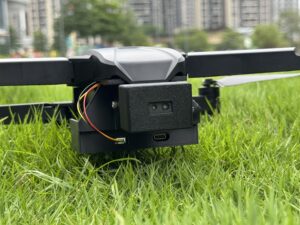
Direct time-of-flight, or dToF, LiDAR measures the time required for emitted light to return from a target. Solid-state dToF modules are attractive for drones because they avoid bulky rotating mechanisms and can fit into compact airframes. A small UAV has strict limits on mass, power, mounting space, and vibration tolerance. A lightweight depth module can support forward obstacle detection, downward altitude hold, wall following, or indoor navigation without consuming the payload budget of a larger scanner.
Limits of LiDAR
Engineering credibility requires naming the limits. Sunlight can affect optical ranging performance. Highly reflective, transparent, dark, or absorptive surfaces can influence signal quality. Field of view must be planned carefully because one fixed sensor does not cover every direction. Multiple sensors may be required for wider safety coverage. Algorithms still matter. A depth map does not automatically become an avoidance decision. Flight speed must match sensing range, frame rate, processing latency, and braking capability. LiDAR is powerful, but it has to be integrated as part of a complete UAV safety architecture.
How to Choose a LiDAR Sensor for Drone Collision Avoidance
1. Ranging Capability
Range should be evaluated separately for indoor, nighttime, and outdoor daytime conditions. Outdoor sunlight performance is especially important because ambient light can reduce the effective range of some optical sensors. A slow inspection drone flying near walls, bridges, tanks, or machinery may only need reliable range of several meters. A faster mapping drone needs longer detection distance. If the UAV travels too far during the time needed to sense, process, decide, and brake, the sensor range may be insufficient even when the range data itself is accurate.
2. Ranging Accuracy
Centimeter-level accuracy helps define safer thresholds. If a sensor reports distance with large uncertainty, engineers have to add wider safety margins, which may cause unnecessary stops or make close inspection difficult. Accurate range data supports stable altitude hold, reliable close-object detection, better local mapping, and more predictable obstacle avoidance behavior. For example, a drone designed to maintain a controlled distance from a wall during inspection benefits from consistent measurements rather than noisy readings that make the aircraft surge forward and backward.
3. Field of View
Field of view determines how much space the sensor can observe at one time. A wider field of view helps cover more area, but the usable angular detail also depends on resolution and sensor design. A forward-facing UAV LiDAR sensor may need enough horizontal FOV to detect obstacles during turns and enough vertical FOV to detect objects above or below the flight path. Downward-facing sensors for altitude hold may require a different FOV than side-facing sensors for structure inspection. Engineers should map the sensor FOV against the drone body, propeller guards, landing gear, camera gimbals, and expected obstacle directions.
4. Resolution
Resolution describes how many depth samples are available in each frame. A 40 × 30 depth sensor provides 1,200 depth points per frame. That is not the same as a high-resolution camera image, but it can be very useful for detecting larger obstacles, surfaces, openings, and navigation boundaries. For drone collision avoidance, resolution affects the ability to distinguish obstacle shape and estimate whether a region is safe. Small wires and thin branches remain difficult for many sensors, so mission planning and sensor fusion are still important.
5. Frame Rate and Latency
Collision avoidance is time-sensitive. A 10 fps sensor updates about every 100 milliseconds. For slow to moderate-speed inspection drones, hover assistance, indoor navigation, and close-range operation, this can be practical if the control logic is conservative. For faster aircraft, engineers may need a longer detection range, higher frame rate, or both. Frame rate should be evaluated together with processing time, communication delay, flight-controller response, and braking distance. The real safety question is whether the UAV can detect and respond before it reaches the obstacle.
6. Weight and Size
Every gram affects flight time, payload capacity, and stability. Small drones may have only a narrow payload margin after accounting for cameras, batteries, communication modules, and protective frames. Compact sensors are also easier to mount in multiple directions, such as front and bottom, without throwing off the airframe balance. A lightweight LiDAR module can be integrated into an enclosure, gimbal-adjacent housing, payload bay, or custom bracket, as long as the field of view is not blocked.
7. Power Consumption
Lower power consumption reduces battery burden and heat management requirements. A 1–2 W class sensor is attractive for embedded UAV systems because it can provide active depth sensing without consuming the power budget of a larger perception payload. Power design should still account for voltage regulation, startup current, cable length, electromagnetic noise, and thermal conditions inside the drone body. A stable power supply is essential for reliable sensor operation during aggressive maneuvers or changing battery voltage.
8. Interface Compatibility
Interface selection determines integration complexity. UART is useful for embedded controllers and simple data communication. UDP is suitable for network-based systems and richer data streams. UVC can make a depth module easier to prototype with PCs or Linux-based platforms by treating the sensor more like an imaging device. UAV developers should confirm whether the sensor can communicate with the flight controller directly or whether a companion computer is required. Developers building companion-computer prototypes may also be interested in embedded development platforms such as the RISC-V Dev Board HM-RV3.
9. Environmental Operating Range
Temperature, vibration, sunlight, enclosure design, and electromagnetic compatibility all affect field performance. A drone used for inspection may see hot outdoor surfaces, cold storage areas, wind vibration, dust, and changing light conditions in a single mission. Engineers should evaluate the sensor’s operating temperature, mechanical mounting, lens protection, and software filtering under real mission conditions. It is also good practice to test in the same lighting and target materials expected during operation.
10. SDK and Developer Support
Good hardware can become painful to use without software support. SDKs, sample code, data visualization tools, calibration guidance, and documentation speed up development. Support for Windows, Linux, and ARM Linux is valuable because many UAV teams prototype on PCs, then deploy on embedded companion computers. Data logging and replay are also important because engineers need to analyze false positives, missed detections, and edge cases after test flights.
Need a compact LiDAR module for UAV obstacle avoidance?
Explore the DTOF Solid State LiDAR HM-LD1 for lightweight 3D depth sensing, point cloud output, and embedded UAV development.
Sensor Placement, Field of View, and Blind Spot Coverage
Forward Collision Avoidance
Forward-facing sensors are the most common starting point because many UAV missions involve forward flight. They help with corridor navigation, return-to-home protection, bridge approaches, warehouse aisles, and inspection paths. The sensor should be mounted so propellers, landing gear, payloads, or airframe components do not block the field of view. If the drone flies quickly or turns aggressively, a forward-only sensor may not detect side hazards soon enough.
Downward LiDAR for Altitude Hold and Terrain Following
A downward-facing LiDAR sensor can support precision landing, terrain-relative altitude, indoor hover, low-altitude mapping, and agricultural flight. Barometric altitude can drift, GPS altitude may not be precise enough close to the ground, and vision-based systems can struggle on low-texture surfaces. Direct range measurement to the ground or nearby surface helps maintain clearance. However, surface angle, reflectivity, vegetation, and sensor mounting angle should be tested carefully.
Side Sensors for Structure Inspection
Side-facing sensors are valuable for drones that inspect walls, bridges, racks, pipelines, tanks, mining faces, or building facades. Maintaining a constant side distance improves image quality, protects the payload, and reduces pilot workload. A side sensor can also help prevent drift into structures during wind gusts or when GNSS is unreliable. For close inspection, the control algorithm should avoid overreacting to small surface features while still responding to large obstacles.
Upward Obstacle Detection
Upward sensing is often ignored until the drone operates indoors, under bridges, in tunnels, in forests, or near overhead utilities. A UAV can climb into ceilings, beams, pipes, branches, or bridge decks if upward clearance is not monitored. This is especially important during automated recovery, vertical takeoff, return-to-home climbs, and indoor inspection. Upward sensors must be protected from propeller wash, vibration, and mounting obstructions.
Multi-Sensor Fusion for 360° Safety
One sensor rarely provides complete drone collision avoidance. A fixed solid-state LiDAR has a defined field of view and blind spots. Full industrial coverage may require front, rear, side, top, and bottom sensing. Sensor fusion can combine LiDAR, cameras, radar, IMU data, GNSS, optical flow, and SLAM. The correct architecture depends on the mission. A warehouse drone may prioritize front, side, top, and bottom sensing, while a terrain-following agricultural UAV may prioritize downward and forward-downward depth measurement.
UAV Integration Architecture: Flight Controllers, Companion Computers, and SDKs
Basic Architecture
A typical UAV perception chain starts with the LiDAR module, passes data to an embedded processor or companion computer, runs obstacle detection algorithms, sends commands to the flight controller, and finally produces motor control responses. The hardware connection may look simple on the bench, but the engineering challenge is timing and reliability. If the perception system reports an obstacle too late, or if the command path is delayed, the aircraft may still collide even though the sensor detected the object.
Companion Computer vs. Direct Flight Controller Integration
Direct integration can be appropriate for simple distance thresholds, such as stopping when a forward range measurement falls below a limit. More advanced applications usually need a companion computer. Point cloud processing, SLAM, mapping, AI fusion, object tracking, and region-based depth analysis require more processing power than many flight controllers provide. A compact LiDAR with UART, UDP, and UVC options gives engineers flexibility to prototype on a PC, develop on embedded Linux, and then deploy into a UAV platform.
Data Types: Distance, Depth Map, and Point Cloud
Different data outputs support different functions. A single-zone distance value may be enough for a basic stop-and-hover function. A depth map supports region-based decisions, such as checking whether the center of the flight path is blocked while the upper area is clear. A point cloud supports richer 3D mapping, SLAM, and environmental perception. For robotics integration ideas and autonomous platform concepts, see the RoboBaton autonomous robotics platform.
Software Development Requirements
UAV integration requires more than reading a data stream. Engineers should plan for SDK availability, Linux support, ARM Linux support, visualization tools, calibration, real-time processing, logging, replay, failsafe states, and flight-test procedures. A development team should define what happens if the sensor disconnects, if the data is noisy, if the obstacle is outside the FOV, or if the flight controller rejects a command. Robust collision avoidance requires predictable behavior during both normal operation and failure conditions.
Recommended dToF LiDAR Module for Drone Collision Avoidance: HM-LD1
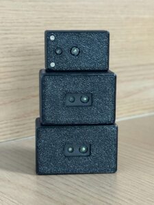
The DTOF Solid State LiDAR HM-LD1 is a compact 3D depth-sensing module designed for robotics, UAVs, smart inspection, obstacle avoidance, distance detection, autonomous navigation, and embedded vision development. It is based on SPAD direct time-of-flight technology and provides real-time depth images and 3D point cloud data. For drones, its low 28 g weight, low 1.2 W power consumption, compact body, and UART/UDP/UVC interfaces make it practical for prototyping and integration into small UAV platforms.
The HM-LD1 is especially relevant for close-range drone collision avoidance because it offers 0.2–8 m outdoor ranging and 0.5–25 m indoor ranging, with ±3 cm ranging accuracy. Outdoor measurement up to 8 m is suitable for slow inspection, controlled navigation near structures, and low-altitude missions where UAV speed is managed conservatively. Indoor or nighttime ranging up to 25 m supports warehouse drones, enclosed-space navigation, security robots, and development platforms operating where GNSS is unavailable.
The module supports point cloud and depth map visualization, which helps developers inspect sensor output during testing. It can be integrated with PCs, Raspberry Pi-class boards, flight controllers, and embedded platforms. MRP offers SDKs for x86 Windows, x86 Linux, and ARM Linux, supporting development across desktop and embedded systems. The product page also provides a downloadable DTOF SSL HM-LD1 Product Brochure.
| Specification | DTOF Solid State LiDAR HM-LD1 | Why It Matters for Drone Collision Avoidance |
|---|---|---|
| Technology | SPAD dToF solid-state LiDAR | Provides direct time-of-flight depth sensing without a bulky rotating mechanism. |
| Dimensions | 43.5 mm × 30 mm × 26.5 mm | Compact size supports integration into small UAV frames and embedded payload bays. |
| Weight | 28 g | Low weight helps preserve flight time and payload capacity. |
| Indoor Ranging Capability | 0.5–25 m | Useful for warehouses, tunnels, indoor inspection, laboratories, and nighttime missions. |
| Outdoor Ranging Capability | 0.2–8 m | Supports close-range outdoor obstacle detection and inspection navigation. |
| Ranging Accuracy | ±3 cm | Centimeter-level distance accuracy helps define safer avoidance thresholds. |
| Field of View | 60° horizontal × 45° vertical | Provides area-based depth perception rather than a single narrow distance beam. |
| Resolution | 40 × 30 | Generates 1,200 depth points per frame for obstacle shape and surface awareness. |
| Frame Rate | 10 fps | Suitable for real-time depth updates in slow to moderate-speed UAV navigation and inspection scenarios. |
| Interfaces | UART / UDP / UVC | Supports embedded controllers, networked systems, PCs, Raspberry Pi-class boards, and development platforms. |
| Operating Temperature | -20 ℃ to 60 ℃ | Supports operation across many indoor and outdoor industrial environments. |
| Power Consumption | 1.2 W | Low power draw is beneficial for battery-powered drones. |
| Output Data | Depth image and 3D point cloud data | Useful for obstacle avoidance, SLAM, navigation, and robotic vision development. |
| SDK Support | x86 Windows, x86 Linux, ARM Linux | Helps developers integrate the module into PC-based tools and embedded UAV systems. |
The product description also emphasizes compact and lightweight integration for autonomous mobile robots and drones where weight affects flight distance. One product text reference describes a compact housing as 43.5 mm × 43.5 mm × 28.5 mm, while the formal dimensions table lists 43.5 mm × 30 mm × 26.5 mm. For production mechanical design, engineers should confirm the latest mechanical drawing and mounting envelope from the product page or brochure before finalizing the airframe enclosure.
View Product Details & Pricing ➔
Industrial Use Cases for LiDAR-Based Drone Collision Avoidance
Bridge, Dam, and Expressway Inspection
Infrastructure inspection drones often fly close to concrete, steel, cables, beams, expansion joints, and uneven surfaces. Drone collision avoidance helps maintain controlled separation from structures while collecting visual or thermal data. LiDAR-based depth sensing can support approach control, side distance awareness, and safer navigation under bridges or near dam walls. The ability to obtain reliable distance data is valuable when human access is difficult or dangerous.
Mining and Quarry UAV Operations
Mines and quarries present dust, walls, elevation changes, poor GNSS geometry, and moving machinery. UAVs may need to inspect slopes, stockpiles, conveyor systems, or confined areas. Local obstacle sensing reduces dependence on GNSS and helps the drone react to nearby terrain and structures. In dusty environments, LiDAR may be combined with radar and conservative flight rules to improve operational safety.
Warehouse and Indoor UAV Navigation
Indoor drones cannot rely on GPS. Warehouses also include racks, ceilings, forklifts, people, pallets, cables, and narrow aisles. LiDAR depth sensing can help detect walls, shelves, ceiling structures, and moving obstacles. For indoor drone collision avoidance, the 0.5–25 m indoor ranging capability of a compact depth module can be useful for navigation experiments, security patrols, inventory support, and autonomous inspection.
Power Line and Utility Inspection
Utility inspection is challenging because wires can be thin, towers are complex, and wind can move both the drone and cables. LiDAR can assist with distance awareness near poles, towers, and larger structural elements, but thin wires may require additional sensors, cameras, mission planning, and conservative stand-off distances. A robust utility UAV should combine multiple perception methods and avoid relying on a single sensor to detect every hazard.
Agriculture and Terrain Following
Low-altitude agricultural drones benefit from terrain-relative altitude control. A downward or forward-downward LiDAR can help maintain a target clearance over crops, uneven ground, irrigation features, and field structures. Terrain following improves spraying consistency, mapping quality, and safety during low-altitude missions. The sensor must be tested over vegetation because plant surfaces can be irregular and may produce variable returns.
Security, Patrol, and Perimeter Monitoring
Autonomous patrol drones may operate around buildings, fences, warehouses, campuses, or industrial yards. LiDAR can assist with zone intrusion monitoring, distance detection, and safer route execution. For security use, collision avoidance should be combined with geofencing, visual cameras, reliable communications, and emergency stop procedures. A depth-sensing module can help the drone slow or hover when objects enter the patrol route.
Testing and Validating Collision Avoidance Performance
Bench Testing
Before flight, engineers should verify data output, interface communication, frame rate, power stability, and software parsing. Depth maps or point clouds should be visualized against known objects at measured distances. Bench testing should include startup behavior, cable movement, voltage variation, and data dropouts. If the sensor is used with a companion computer, CPU load and communication latency should be measured before attaching the system to a drone.
Static Obstacle Testing
Static testing should use walls, poles, boxes, mesh, branches, angled surfaces, bright surfaces, dark surfaces, and reflective targets. Tests should be repeated in bright sunlight, shade, low light, and indoor lighting. The goal is to identify both reliable detection zones and weak conditions. Engineers should record when the sensor detects an obstacle, when it fails, and whether false returns occur.
Flight Envelope Testing
Flight testing should expand gradually. Start with hover tests, then low-speed approaches, lateral movement, descent tests, return-to-home simulation, indoor corridor tests, and outdoor sunlight tests. Each step should include a safe pilot override and sufficient clearance. Testing should not jump directly from bench validation to autonomous operation near valuable infrastructure. Industrial customers expect repeatability, and repeatability requires controlled test procedures.
False Positive and False Negative Analysis
A false positive occurs when the drone thinks an obstacle exists when it does not. This can interrupt missions, cause unnecessary hovering, or create operator frustration. A false negative occurs when the drone fails to detect a real obstacle. This is a safety risk. Both types of errors matter. Good validation records the target material, distance, lighting, flight speed, sensor angle, and software decision so the engineering team can tune thresholds and improve algorithms.
Speed, Range, and Braking Distance
The detection range must exceed the distance traveled during sensing, processing, decision-making, and braking. A drone moving slowly near a bridge can use shorter-range perception than a fast mapping drone. A 10 fps sensor may be effective in controlled low-speed conditions but insufficient for aggressive flight if the UAV travels too far between updates. Engineers should define maximum allowed speed for each sensing mode and enforce those limits in software.
Buying Checklist for UAV LiDAR Collision Avoidance Sensors
Use the following checklist when evaluating a drone anti-collision sensor for development or deployment:
- ✅ Does the sensor provide enough outdoor range for the UAV’s flight speed?
- ✅ Is the ranging accuracy sufficient for the safety margin?
- ✅ Does the field of view cover the intended collision direction?
- ✅ Is the sensor light enough for the drone payload budget?
- ✅ Can the drone supply the required power without reducing mission time too much?
- ✅ Does the interface match the flight controller or companion computer?
- ✅ Does the module output raw distance, depth map, or point cloud data?
- ✅ Is SDK support available for the target operating system?
- ✅ Can the sensor operate in the expected temperature range?
- ✅ Has the sensor been tested in lighting conditions similar to the mission environment?
- ✅ Can multiple sensors be synchronized or installed for broader coverage?
- ✅ Is technical support available for integration and troubleshooting?
Engineers evaluating compact depth sensors for UAV collision avoidance can review the HM-LD1 specifications or compare other modules in the product catalog.
a short-flex design and a long-flex design for different robotics and UAV d…
Drone Collision Avoidance FAQ
Is drone collision avoidance essential, or can experienced pilots fly safely without it?
What is the cheapest effective anti-collision setup for a DIY drone?
Are drones with collision avoidance really as good as advertised in industrial environments like mining or inspection?
What is the difference between obstacle avoidance and collision avoidance?
Is LiDAR better than cameras for drone obstacle avoidance?
How much LiDAR range does a drone need for collision avoidance?
Can one LiDAR sensor provide full 360-degree drone collision avoidance?
What interfaces are important when selecting a LiDAR module for UAV development?
Does frame rate matter for drone collision avoidance?
Can LiDAR help with drone altitude hold and terrain following?
Build Safer UAV Navigation with Compact LiDAR Depth Sensing
Drone collision avoidance depends on reliable sensing, correct placement, and robust integration. If your UAV project requires lightweight 3D depth data for obstacle detection, altitude hold, or autonomous navigation, HM-LD1 offers a practical dToF LiDAR module for development and deployment.
📚 References & Further Reading
- Industry Standard: u-blox positioning technologies for autonomous platforms
- Industry Standard: RoboSense LiDAR ecosystem for autonomous sensing
- Related Guide: My Robot Project robotics and UAV product catalog
- Related Guide: DTOF Solid State LiDAR HM-LD1 product page