Obstacle Sensing Module for Robots & Drones: How to Choose Reliable LiDAR-Based Obstacle Detection
Here’s the deal: robots and drones rarely fail for one clean, dramatic reason. It is not always the motor, the battery pack, or the control loop. In the shop and out in the field, a lot of failures come from something more basic: the machine simply does not understand what is sitting in front of it. A low-cost ultrasonic or infrared obstacle sensing module may look fine on a bench, but real deployments are not bench tests. Sunlight, reflective surfaces, black plastic, soft materials, narrow detection zones, vibration, and vehicle speed can all expose weak sensing hardware fast.
For autonomous mobile robots, UAVs, inspection robots, service robots, and industrial automation equipment, unreliable obstacle detection is not a small inconvenience. It can mean collision risk, downtime, damaged payloads, failed customer trials, and a whole lot of engineering hours spent trying to filter bad data. Look, no amount of clever software can fully rescue a sensor that is blind in the conditions where the machine actually works.
This guide explains how to choose a reliable obstacle sensing module for robots and drones, with a focus on modern LiDAR-based and dToF depth sensing modules. You will learn how different sensing technologies work, where ultrasonic and IR modules fall short, why field of view and frame rate matter, how 3D point clouds improve navigation, and what specifications to check before integrating a module into an embedded system.
We will also look at the DTOF Solid State LiDAR HM-LD1, a compact SPAD dToF LiDAR module designed for obstacle avoidance, distance detection, autonomous navigation, smart inspection, robotic vision development, UAV altitude hold, terrain following, and embedded perception projects.
Looking for a compact LiDAR obstacle sensing module for robots or UAVs? Explore the DTOF Solid State LiDAR HM-LD1 for depth imaging, point cloud output, and embedded platform integration.
Table of Contents
- 👉 What Is an Obstacle Sensing Module?
- 👉 Why Reliable Obstacle Detection Matters for Robots and Drones
- 👉 Common Obstacle Sensing Technologies Compared
- 👉 How LiDAR-Based Obstacle Sensing Works
- 👉 dToF vs iToF: Which Is Better for Obstacle Detection?
- 👉 How to Choose an Obstacle Sensing Module
- 👉 Obstacle Sensing Modules for Robots
- 👉 Obstacle Sensing Modules for Drones and UAVs
- 👉 Integration Guide: Interfaces, SDKs, ROS, and Embedded Platforms
- 👉 Recommended LiDAR Obstacle Sensing Module: DTOF Solid State LiDAR HM-LD1
- 👉 Obstacle Sensing Technology Comparison Table
- 👉 Common Obstacle Sensing Errors and How to Avoid Them
- 👉 Engineering Buying Checklist for an Obstacle Sensing Module
- 👉 Related Technologies and Further Reading
- 👉 FAQ: Obstacle Sensing Modules for Robots and Drones
What Is an Obstacle Sensing Module?
An obstacle sensing module is an integrated device that detects nearby objects, measures distance or proximity, and outputs usable data to a controller, computer, flight controller, or embedded processor. In its simplest form, it may send a digital high or low signal when an object enters a detection zone. In a more capable system, it can output analog distance values, serial ranging data, a two-dimensional depth image, or a three-dimensional point cloud that describes the shape and position of objects in the environment.
The term shows up all over robotics, drones, AGVs, AMRs, smart cameras, industrial inspection systems, automated docking devices, security monitoring, and embedded vision systems. A small classroom robot may only need a short-range binary obstacle avoidance board. A warehouse AMR, inspection UAV, or autonomous service robot usually needs richer data, better environmental adaptability, and a communication interface that can support real-time decision-making.
Obstacle Sensor vs Obstacle Sensing Module
A sensor is often the sensing element itself, such as an ultrasonic transducer, infrared receiver, photodiode, image sensor, or LiDAR detector. A module is usually more complete. It may include optics, electronics, processing firmware, calibration data, power regulation, housing, mounting features, and a defined output protocol. That distinction matters in industrial engineering because integration time, reliability, documentation, and repeatability usually depend on the full module design, not just the raw sensing element.
From Simple Detection to 3D Perception
A basic obstacle avoidance module may answer only one question: “Is something close?” That can be enough for a toy robot or simple line-following platform. A LiDAR-based obstacle sensing module answers more useful questions: “How far away is the obstacle?”, “Where is it inside the field of view?”, “How large is the object?”, “Is there free space to the left or right?”, and “How does the obstacle geometry change over time?”
This richer perception is why depth maps and point clouds matter for SLAM, navigation, path planning, and collision prevention. In the shop, the difference between a binary sensor and a true depth module is the difference between a warning light and a usable map of nearby space.
To understand the broader technology behind laser-based distance measurement, see our guide: What Is LiDAR Technology?
Why Reliable Obstacle Detection Matters for Robots and Drones
Reliable obstacle detection is not an optional feature in autonomous machines. It affects safety, productivity, customer confidence, and project success. A robot that cannot detect a chair leg, pallet edge, glass wall, cable, shelf, person, or moving forklift may stop unexpectedly, collide with equipment, damage payloads, or create unsafe operating conditions. A drone that cannot detect trees, poles, railings, bridges, walls, or uneven terrain may lose stability, crash, or fail an inspection mission.
Robots and drones operate in dynamic spaces. People walk through robot paths, shelves reflect light differently, black surfaces absorb optical signals, glass creates confusing reflections, vegetation introduces irregular shapes, and industrial sites often contain dust, vibration, and electrical noise. A strong obstacle sensing module must be selected according to real operating conditions, not just clean laboratory specifications.
Robot Safety and Productivity
AMRs, AGVs, cleaning robots, service robots, delivery robots, and inspection robots must continuously interpret the environment around them. If the sensing module misses obstacles or produces unstable readings, the navigation stack may generate emergency stops, conservative speed limits, path planning errors, or localization instability. In a warehouse, that reduces throughput. In a public service environment, it reduces trust. In inspection robotics, it may prevent the system from reaching the very areas it was purchased to inspect.
UAV Stability and Collision Prevention
Drones require obstacle detection for forward flight, altitude hold, terrain following, landing assistance, bridge inspection, dam inspection, expressway monitoring, and confined-space navigation. A UAV may need downward-facing sensing to maintain height above uneven terrain, forward-facing sensing to avoid walls or trees, and side-facing sensing for narrow corridors or infrastructure inspection.
Because drones are weight- and power-sensitive, the best module is not simply the one with the longest range. You have to balance accuracy, field of view, update rate, size, weight, power consumption, and integration effort. A sensor that looks impressive on a datasheet can still be a bad fit if it drains the battery, adds too much payload, or cannot talk cleanly to the flight computer.
Industrial Consequences of Poor Sensor Choice
Poor sensor selection creates business risk. Engineering teams may spend weeks tuning filters to compensate for weak raw data. Support teams may receive repeated complaints about false stops or collisions. Purchasing teams may face replacement costs if a module cannot survive field conditions. Product managers may experience delayed launches because the sensing subsystem cannot pass validation. Choosing the right obstacle sensing module early can reduce integration delays, RMA rates, support tickets, and failed deployments.
Common Obstacle Sensing Technologies Compared
Obstacle detection can be implemented with several technologies, each with strengths and limitations. The best choice depends on range, environment, target object type, speed, compute budget, power budget, and required output data. Here’s the practical breakdown.
Ultrasonic Obstacle Sensing Modules
Ultrasonic modules emit sound waves and measure the time required for echoes to return. They are inexpensive, simple to use, and work in darkness. They are common in basic robotics and short-range proximity detection.
But ultrasonic sensing has real limitations. The acoustic beam is relatively wide, angular resolution is poor, soft materials can absorb sound, angled surfaces can deflect echoes away from the receiver, and multiple ultrasonic sensors can interfere with one another. Update rates are also usually slower than optical measurement methods, which can be a problem for fast-moving robots.
Infrared Obstacle Avoidance Modules
Infrared modules emit IR light and detect reflected energy. They are compact, low-cost, and easy to integrate into simple indoor robots. Many educational robots use IR obstacle avoidance modules because they only need short-range detection.
In industrial use, IR modules can be unreliable because sunlight may interfere with the receiver, dark or black surfaces may reflect poorly, shiny surfaces may create unexpected readings, and many low-cost modules provide only binary detection rather than accurate metric depth. They are useful parts, but they are not magic.
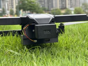
Stereo Vision and Depth Cameras
Stereo vision estimates depth by comparing images from two cameras. Depth cameras may also use structured light or time-of-flight techniques. These systems can provide rich visual data and support AI object recognition.
However, they often require more compute power, careful calibration, and adequate lighting or scene texture. Motion blur, low light, repetitive textures, and reflective surfaces can degrade performance. Stereo vision is powerful when visual recognition is required, but it may not be the simplest option for pure geometry-based obstacle detection.
Radar Modules
Radar modules are strong in dust, fog, rain, and long-distance detection. They are often used in automotive, outdoor vehicle, and harsh-environment applications. Their main limitation is spatial resolution. Radar can detect objects at range, but it may be harder to classify small obstacles, define sharp object boundaries, or create detailed 3D geometry compared with LiDAR or depth imaging modules.
LiDAR and Time-of-Flight Modules
LiDAR and time-of-flight modules measure distance using light travel time. Depending on design, they can output a single distance, multi-zone range data, a depth map, or a 3D point cloud. LiDAR-based obstacle sensing is strong for geometry-based perception because it directly measures distance rather than relying only on image appearance.
This makes it useful for autonomous navigation, SLAM, obstacle segmentation, zone intrusion monitoring, smart inspection, and robotic vision development.
For a general background on laser detection and ranging, reference the overview from Wikipedia’s LiDAR entry. For deeper photonics research and industry context, see the IEEE Photonics Society.
How LiDAR-Based Obstacle Sensing Works
A LiDAR-based obstacle sensing module measures distance by emitting light and detecting the reflected signal from nearby surfaces. In a direct time-of-flight design, the module calculates distance based on the travel time of the light pulse. Because light travels extremely fast, the electronics and detection system must measure very small time intervals. Modern solid-state LiDAR modules combine optics, sensors, timing circuits, and firmware to provide usable depth data for robots and drones.
Basic Principle of Time-of-Flight Measurement
The module emits light toward a target area. When the light reaches an object, part of it reflects back to the receiver. The module measures the time between emission and return. Since the speed of light is known, the distance can be calculated from that round-trip time. This optical measurement can be performed rapidly, enabling real-time sensing for navigation and collision prevention.
What Is a Depth Map?
A depth map is a two-dimensional grid where each pixel or cell stores a distance value. Instead of a normal image where pixels represent color or brightness, a depth map represents how far surfaces are from the sensor. This is highly useful for obstacle sensing because engineers can define near-field warning zones, detect object shapes, segment free space, and trigger control actions based on distance thresholds.
Depth maps can be processed using OpenCV, ROS, embedded algorithms, or custom perception software. In practical terms, a depth map gives the software a usable picture of distance, not just a yes-or-no obstacle signal.
What Is a Point Cloud?
A point cloud represents spatial points in three-dimensional coordinates. Each point corresponds to a measured location in space. Point clouds help robots understand object boundaries, walls, ramps, shelves, pallets, and other environmental structures.
In SLAM and autonomous route planning, point cloud data can support mapping, localization, obstacle segmentation, and navigation decisions. For industrial systems, point cloud output is often more valuable than simple “object detected” signals because it provides context.
Why Field of View Matters
Field of view determines how much of the environment the obstacle sensing module can observe. A narrow sensor may accurately measure one direction while missing an obstacle slightly to the side, above, or below the beam. A wider horizontal field of view helps detect obstacles across the robot’s path. A wider vertical field of view helps detect ramps, ground changes, hanging objects, low objects, and aerial obstacles.
The correct FOV depends on robot speed, stopping distance, mounting position, movement direction, and safety requirements. Look at the full collision envelope of the machine, not just the centerline straight ahead.
Why Frame Rate Matters
Frame rate affects how often the sensing module updates distance information. A slow indoor robot may operate safely with a moderate update rate if its stopping distance is short. A faster AMR or drone must consider sensor FPS, data transfer latency, algorithm processing time, and controller response time.
Frame rate should never be evaluated alone. Total system latency is what determines how quickly the vehicle can respond to a detected obstacle.
dToF vs iToF: Which Is Better for Obstacle Detection?
Time-of-flight depth sensing is commonly divided into direct time-of-flight and indirect time-of-flight. Both methods are useful, but they are optimized differently. Understanding the difference helps engineers choose the right obstacle sensing module for a robot, drone, inspection system, or embedded platform.
What Is Direct Time-of-Flight?
Direct time-of-flight, or dToF, measures the direct travel time of emitted light pulses. The sensor detects returned photons and calculates distance from the time delay. SPAD-based dToF systems can detect very weak returned signals, which is valuable in compact LiDAR modules.
dToF is often suitable for longer-range measurement and can be a strong choice for obstacle avoidance, distance detection, and outdoor-capable robotic perception.
What Is Indirect Time-of-Flight?
Indirect time-of-flight, or iToF, typically measures the phase shift between emitted and reflected modulated light. It is commonly used in depth cameras for short to medium range applications. iToF can be effective and compact, but it may face range ambiguity or interference depending on modulation, ambient light, and environment.
Why SPAD dToF Is Valuable for Robots and UAVs
SPAD dToF technology is valuable because it combines high sensitivity, compact implementation, and real-time depth output. For robots and UAVs, the module must be small, efficient, and capable of providing actionable distance data. A SPAD dToF LiDAR obstacle sensing module can support depth maps and point clouds while remaining suitable for embedded systems, autonomous navigation, UAV altitude hold, terrain following, and collision prevention.
How to Choose an Obstacle Sensing Module
Selecting an obstacle sensing module is an engineering decision, not just a component purchase. The module must match the physical platform, environment, software architecture, safety goals, and production requirements. Here are the points I would check before signing off on a sensor for a real robot or drone.
1. Ranging Distance
Define the required indoor and outdoor range separately. Indoor conditions are usually easier because ambient light is controlled. Outdoor applications must account for sunlight, target reflectivity, weather, and distance. Mobile robots need enough range to stop safely before impact. UAVs need enough distance for forward obstacle detection, altitude hold, terrain following, and landing assistance.
2. Accuracy and Repeatability
Accuracy affects navigation stability, docking precision, obstacle classification, and control confidence. Repeatability is equally important because unstable measurements can cause a robot to oscillate, stop unnecessarily, or misjudge free space. Accuracy may vary by target color, material, angle, distance, and lighting condition. A module with ±3 cm-class ranging accuracy can be valuable for compact robotics and UAV applications, but engineers should validate performance with real target materials.
3. Field of View
Field of view should be matched to the robot’s collision envelope and movement pattern. A single-point distance sensor may be insufficient for wide robots, turning vehicles, or drones moving through complex spaces. A depth sensing module with horizontal and vertical FOV provides more spatial context. Multiple modules may still be required for 360-degree coverage, side detection, rear detection, or redundant safety sensing.
4. Resolution
Resolution determines how many depth points are available in each frame. Higher resolution can improve object boundary detection, shape recognition, and obstacle segmentation. Lower resolution may still be enough for proximity sensing, zone intrusion monitoring, and terrain following. The best resolution depends on compute capacity, bandwidth, object size, detection distance, and algorithm requirements.
5. Frame Rate and Latency
Frame rate is only one part of responsiveness. Total latency includes sensor exposure and processing time, communication delay, software filtering, perception algorithm processing, and controller response. A robot moving slowly in a controlled space can tolerate more latency than a fast drone or AMR. Engineers should calculate stopping distance and add safety margins for unexpected obstacles and moving people.
6. Interface Compatibility
Interface selection affects integration effort. UART is useful for microcontrollers, embedded controllers, and flight controllers. UDP is suitable for higher-throughput networked applications, including depth frames or point cloud data. UVC is useful for PC development and camera-style integration. SDK support for Linux, Windows, ARM platforms, and x86 systems can significantly reduce development time.
7. Power Consumption
Battery-powered robots and drones require careful power budgeting. A low-power obstacle sensing module reduces heat, improves endurance, and simplifies power supply design. UAVs are especially sensitive because every watt and gram can affect flight time. Engineers should also consider startup current, power filtering, connector reliability, and thermal behavior in enclosed housings.
8. Size and Weight
Compact modules simplify mechanical design. A small module can be mounted on a drone, mobile robot bumper, inspection robot head, camera assembly, or embedded device with limited internal space. Weight is particularly important in UAVs, where payload affects flight time, control stability, and mission capability. Mechanical integration should include mounting rigidity, vibration isolation, lens protection, and service access.
9. Outdoor Adaptability
Outdoor sensing is challenging because sunlight adds strong ambient optical noise. Reflective targets, dark surfaces, water, vegetation, dust, fog, and rain may affect measurement reliability. Always compare indoor and outdoor range specifications. Field testing should include expected time of day, weather, target materials, and mounting orientation.
10. Software and Technical Support
Industrial projects need more than a sensor. They need documentation, SDKs, sample code, protocol descriptions, calibration guidance, and engineering support. Long-term supply is also critical for productized robots and UAVs. Source factory manufacturing, stable production, and customization options can reduce procurement risk and support future product iterations.
Need depth data, point cloud output, and embedded platform support? HM-LD1 supports UART, UDP, UVC, x86 Windows, x86 Linux, and ARM Linux SDKs.
Obstacle Sensing Modules for Robots
Robot obstacle sensing requirements vary widely depending on application. A compact indoor service robot may need short-range front detection, while an AMR in a warehouse may require multi-directional coverage, integration with SLAM, and reliable detection of people, pallets, racks, and forklifts.
AMR and AGV Obstacle Avoidance
AMRs and AGVs operate near people, storage racks, pallets, carts, forklifts, and variable floor conditions. Obstacle sensing modules help detect objects that may not be included in the map or may move unexpectedly. Reliable depth data can feed navigation stacks, safety zones, and speed control algorithms.
For industrial productivity, predictable sensing is essential because false positives create unnecessary stops, while missed obstacles create collision risk. In the shop, both problems cost money.
Service Robots and Delivery Robots
Service and delivery robots navigate through doorways, corridors, furniture, people, glass partitions, stairs, and reflective surfaces. These robots often benefit from front-facing and side-facing depth sensing. A LiDAR obstacle sensing module can help detect near-field objects and define free space, while cameras may support recognition of people, signs, or semantic objects.
Inspection Robots
Inspection robots work in bridges, tunnels, dams, expressways, industrial plants, and other environments where human access may be dangerous or expensive. Depth sensing helps them measure distances, avoid structures, and navigate near complex surfaces. A module with outdoor measurement capability is useful when inspection tasks occur in daylight or mixed lighting conditions.
Robot Vision Development
Depth maps and point clouds are valuable for robot vision development. Engineers can use them for object segmentation, free-space detection, SLAM, path planning, zone intrusion detection, and 3D mapping. Compared with binary obstacle modules, depth output gives software teams more information for robust decisions.
Obstacle Sensing Modules for Drones and UAVs
Drones and UAVs require sensing modules that are compact, lightweight, power efficient, and reliable under vibration. Unlike ground robots, UAVs must manage limited payload, flight endurance, and changing orientation. Obstacle sensing must be considered as part of the full autonomy stack, including flight control, positioning, vision, and mission planning.
Forward Obstacle Detection
Forward-facing obstacle detection helps drones identify walls, trees, poles, cables, railings, and other hazards in the flight path. Detection range must be matched to flight speed and stopping or avoidance distance. A depth sensing module can help determine whether an obstacle is centered in the path or located near the edge of the field of view.
Altitude Hold and Terrain Following
Downward-facing distance measurement can improve altitude estimation close to surfaces and support terrain following over uneven ground. This is useful for agricultural drones, inspection UAVs, low-altitude mapping platforms, and autonomous landing systems. A compact dToF obstacle sensing module can provide real-time distance data without adding excessive payload.
Landing Assistance
Landing assistance requires detection of the ground surface and nearby obstacles during descent. The sensing module may help identify height above ground, uneven terrain, or objects in the landing zone. Reliable measurement is especially important when GPS or visual positioning is limited.
Infrastructure Inspection
UAV inspection missions often involve bridges, dams, expressways, towers, roofs, and other structures that people cannot safely approach. Outdoor daytime performance matters because missions may occur under strong sunlight. Obstacle sensing can be combined with positioning and imaging payloads to improve autonomy and mission safety.
For positioning accuracy in autonomous navigation, you may also compare perception sensors with centimeter-level positioning systems in our article: What Is RTK? The Centimeter-Level GPS Navigation
Integration Guide: Interfaces, SDKs, ROS, and Embedded Platforms
Integration risk is one of the biggest concerns when selecting an industrial obstacle sensing module. A sensor with impressive specifications may still delay a project if the interface is difficult, documentation is incomplete, or software support is weak. Engineers should evaluate the module at the electrical, mechanical, firmware, software, and system levels.
UART Integration
UART is suitable for microcontrollers, flight controllers, and embedded controllers. It is simple, widely supported, and effective for lower-bandwidth data. Depending on implementation, UART may be used for distance values, configuration commands, or simplified sensing output. Developers should confirm baud rate, frame format, command structure, checksum method, and error handling requirements.
UDP Integration
UDP is useful for higher-throughput data transfer over a network. It can support depth frames or point cloud streaming to Linux computers, robotics controllers, or embedded processors. UDP integration requires network configuration, packet handling, synchronization, and loss tolerance. It is often well-suited to robots that already use Ethernet-based computing architectures.
UVC Integration
UVC provides camera-style integration and can simplify prototyping on PCs and embedded systems. Developers may be able to visualize depth output using camera tools or custom applications. UVC can be valuable during early testing because it reduces the effort needed to display and analyze sensor data.
ROS and SLAM Workflow
In a ROS workflow, depth data can be converted into topics, point clouds can be published, and obstacle information can be used by the navigation stack. The sensor data may be fused with odometry, IMU data, RTK positioning, wheel encoders, or visual odometry. Calibration is critical: the sensor coordinate frame must align with the robot frame, and timestamps should be handled correctly to avoid map distortion or delayed obstacle response.
OpenCV and Custom Obstacle Detection
For custom algorithms, engineers can threshold depth maps, segment near-field objects, define warning zones, filter outliers, and track obstacle regions over time. OpenCV can support image-like processing of depth data, including region segmentation and morphological filtering. Robust systems should include temporal filtering, confidence thresholds, and fail-safe logic for missing or invalid data.
Mechanical Placement and Calibration
Mounting position affects performance. A sensor placed too low may see floor texture or be blocked by the robot body. A sensor placed too high may miss low obstacles. Drones must account for propeller vibration, frame flex, and cable strain. The sensor should have a clean optical path, stable mounting, protected lens area, and a known coordinate transform relative to the vehicle frame.
Power and EMC Considerations
Power stability is essential. Motors, ESCs, pumps, and high-current actuators can create voltage dips and electrical noise. Use stable power regulation, appropriate grounding, cable management, and filtering where required. Long cables should be evaluated for signal integrity and connector reliability. Thermal management should be considered if the module is installed inside a sealed enclosure.
Recommended LiDAR Obstacle Sensing Module: DTOF Solid State LiDAR HM-LD1
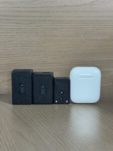
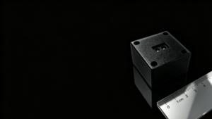
The DTOF Solid State LiDAR HM-LD1 is a compact SPAD dToF LiDAR module designed for real-time depth imaging and 3D point cloud output. It is suitable for obstacle avoidance, distance detection, autonomous navigation, smart inspection, robotic vision development, UAV altitude hold, terrain following, zone intrusion monitoring, object recognition, and embedded perception systems.
HM-LD1 is a solid-state LiDAR module based on SPAD dToF technology. It delivers real-time depth images and 3D point cloud data for accurate environmental perception. It supports indoor or nighttime ranging up to 25 m and outdoor daytime ranging up to 8 m, making it useful for robots, drones, smart inspection systems, security applications, and embedded vision development.
With UVC, UDP, and UART interfaces, it can be integrated with PCs, Raspberry Pi-class platforms, flight controllers, and embedded systems for prototyping and deployment.
View Product Details & Pricing ➔
DTOF Solid State LiDAR HM-LD1 Specifications
| Specification | DTOF Solid State LiDAR HM-LD1 |
|---|---|
| Technology | Solid-state LiDAR based on SPAD dToF technology |
| Dimensions | 43.5 mm × 30 mm × 26.5 mm |
| Weight | 28 g |
| Indoor Ranging Capability | 0.5–25 m |
| Outdoor Ranging Capability | 0.2–8 m |
| Ranging Accuracy | ±3 cm |
| Field of View | 60° horizontal × 45° vertical |
| Resolution | 40 × 30 |
| Frame Rate | 10 fps |
| Interface | UART / UDP / UVC |
| Operating Temperature | -20 ℃ to 60 ℃ |
| Power Consumption | 1.2 W |
| Supported Development Platforms | x86 Windows, x86 Linux, ARM Linux SDKs |
| Typical Applications | Obstacle avoidance, distance detection, autonomous navigation, UAV altitude hold, terrain following, SLAM, robotic vision, smart inspection, zone intrusion monitoring |
Why HM-LD1 Is Suitable for Robots
HM-LD1 is well suited for robotic obstacle detection because it combines compact size, 28 g weight, a 60° horizontal by 45° vertical field of view, depth map support, and 3D point cloud output. For AMRs, service robots, delivery robots, and inspection robots, this allows the perception system to evaluate not only whether an obstacle exists, but also where it is located in the sensing area.
UART, UDP, and UVC interfaces provide flexibility for embedded controllers, onboard computers, and PC-based development. That matters when you are trying to move from lab prototype to field-ready machine without rebuilding the whole electronics stack.
Why HM-LD1 Is Suitable for Drones
Drones need modules that are lightweight and power efficient. HM-LD1 weighs 28 g and consumes 1.2 W, making it suitable for UAV platforms where payload and power budget are limited. Its outdoor ranging capability up to 8 m supports use cases such as terrain following, altitude hold, inspection flight, and obstacle detection in daytime environments. Its compact design helps simplify mechanical integration on UAV frames.
Development and Deployment Advantages
MRP offers SDKs for x86 Windows, x86 Linux, and ARM Linux, enabling development across multiple operating systems and architectures. HM-LD1 can be integrated with PCs, Raspberry Pi-class systems, flight controllers, and embedded platforms. Technical support is available for product integration and application development. Source factory manufacturing supports stable supply, and customization is available on demand for project-specific requirements.
Download the DTOF SSL HM-LD1 Product Brochure
Obstacle Sensing Technology Comparison Table
The following table summarizes common obstacle sensing technologies for robots, UAVs, and embedded systems. It is a practical starting point for selecting the right sensing architecture.
| Technology | Strengths | Limitations | Best Fit |
|---|---|---|---|
| Ultrasonic | Low cost, simple, works in darkness | Wide beam, slow response, poor with soft or angled surfaces | Basic short-range obstacle detection |
| Infrared | Very low cost, compact, easy to use | Sunlight interference, surface color sensitivity, short range | Simple indoor robots and line-following applications |
| Stereo Vision | Rich visual data, object recognition potential | Lighting sensitivity, compute load, calibration complexity | AI vision systems and textured environments |
| Radar | Good in dust, fog, rain, and long range | Lower spatial resolution, harder small-object detection | Outdoor vehicles and harsh environments |
| dToF LiDAR | Accurate distance data, depth maps, point clouds, compact options | Requires optical design and integration care | Robots, drones, SLAM, navigation, obstacle avoidance |
Common Obstacle Sensing Errors and How to Avoid Them
Obstacle sensing errors are rarely caused by one factor only. They usually come from a combination of environmental conditions, mechanical placement, power quality, software filtering, and unrealistic expectations. Engineering validation should test the complete system under realistic operating conditions.
Reflective and Transparent Objects
Glass, mirrors, polished metal, and glossy surfaces can create unexpected reflections. Transparent objects may return weak or confusing signals depending on angle and material. Engineers should test multiple target types and use software filtering, multi-angle sensing, and conservative safety rules where necessary.
Strong Sunlight and Outdoor Conditions
Ambient sunlight can reduce optical sensor performance. Outdoor range specifications should be reviewed carefully, and field testing should include expected lux conditions, target reflectivity, and mission time. If the application requires outdoor daytime operation, do not rely only on indoor maximum range.
Poor Sensor Placement
A module mounted too low may detect the floor or be blocked by the robot chassis. A module mounted too high may miss low obstacles. On drones, propeller vibration and frame resonance can affect stability. The sensor should be mounted with a clear field of view, stable orientation, and a known coordinate relationship to the vehicle frame.
Power Instability
Voltage dips from motors, ESC noise on drones, and poor grounding can affect sensor reliability. Use a stable power supply, proper cable routing, and filtering where required. Industrial systems should validate performance during motor startup, braking, and high-load operation.
Software Filtering Problems
Raw depth data may include noise, invalid points, or outliers. Software should reject unrealistic values, apply temporal filtering, define confidence thresholds, and create safety zones. Over-filtering can introduce latency, while under-filtering can cause false stops. Balance is essential.
Engineering Buying Checklist for an Obstacle Sensing Module
Use this checklist before purchasing or specifying an obstacle sensing module for a robot, UAV, inspection system, or embedded perception device.
- ✅ Required indoor and outdoor detection range
- ✅ Required accuracy and repeatability
- ✅ Horizontal and vertical field of view
- ✅ Depth resolution and point cloud requirements
- ✅ Frame rate and total system latency
- ✅ Interface compatibility: UART, UDP, UVC, USB, Ethernet, or CAN
- ✅ Supported SDKs and operating systems
- ✅ Power consumption and thermal design
- ✅ Module size and weight
- ✅ Environmental operating temperature
- ✅ Outdoor sunlight performance
- ✅ Mechanical mounting and calibration support
- ✅ Availability of documentation and technical support
- ✅ Long-term supply and customization options
If you are developing a robot, UAV, inspection system, or embedded perception device, the HM-LD1 dToF LiDAR module provides compact 3D depth sensing with UART, UDP, and UVC integration options.
Explore HM-LD1 for Your Obstacle Sensing Project
Related Technologies and Further Reading
Obstacle detection is often part of a larger autonomy system. Robots and drones may combine LiDAR, RTK positioning, IMU data, cameras, gimbals, odometry, radar, and onboard computing. If you are designing a complete autonomous navigation stack, evaluate perception, positioning, mapping, control, and mission payload together.
For laser-based depth sensing fundamentals, read What Is LiDAR Technology?. For positioning accuracy in outdoor autonomous systems, read What Is RTK? The Centimeter-Level GPS Navigation. For UAV inspection, obstacle detection is often combined with imaging and gimbal payloads; you may also want to read Why the Tri-Spectral Gimbal Pod Is Game Changer.
FAQ: Obstacle Sensing Modules for Robots and Drones
Which obstacle sensing module is better for robots: ultrasonic, infrared, or LiDAR?
How can I achieve wider or 360-degree obstacle detection?
Why do obstacle sensing errors happen on drones or embedded robots?
What specifications matter most when choosing an obstacle sensing module?
Is a LiDAR obstacle sensing module suitable for outdoor use?
Can an obstacle sensing module be used for SLAM?
What is the difference between a distance sensor and an obstacle sensing module?
How many obstacle sensing modules does a robot need?
What interfaces should I look for in an industrial obstacle sensing module?
Why is field of view important in obstacle detection?
If you are unsure which obstacle sensing module fits your robot, UAV, or inspection system, contact our team for integration guidance and product selection support.
📚 References & Further Reading
- Industry Standard: IEEE Photonics Society
- Industry Standard: Wikipedia LiDAR Overview
- Related Guide: What Is LiDAR Technology?
- Related Guide: What Is RTK? The Centimeter-Level GPS Navigation
- Related Guide: Why the Tri-Spectral Gimbal Pod Is Game Changer
- Product Resource: DTOF Solid State LiDAR HM-LD1