What is LiDAR Technology? The Ultimate B2B Guide to Robotics Perception & dToF Sensors
Look, if you’ve ever spent a long weekend in the shop trying to figure out why an Autonomous Mobile Robot (AMR) keeps tossing emergency brake faults in the middle of a perfectly clear warehouse aisle, you already know the painful truth: machine perception is a hard nut to crack. The global race toward warehouse automation, autonomous logistics, and agricultural robotics has transformed how machines perceive their environments. Historically, robotic platforms relied on basic ultrasonic pingers, noisy radar arrays, or standard RGB cameras to navigate complex environments. However, these traditional methodologies consistently fail when confronted with variable ambient lighting, highly reflective surfaces, or the strict millisecond-level latency demands of industrial safety standards. For B2B buyers, automation engineers, and system integrators, selecting the ideal spatial perception system is no longer just a checkbox on a hardware draft. It is an essential design choice that impacts structural efficiency, system longevity, and the entire operational capability of the automated fleet.
Today, enterprise-grade spatial awareness is defined by a single core technology: LiDAR technology (Light Detection and Ranging)—specifically, the shift toward Direct Time-of-Flight (dToF) Solid-State LiDAR (SSL) systems. This shift has changed modern system deployment. Standard mechanical units with complex rotary mirrors are giving way to solid-state silicon elements that offer greater shock resistance, lower power consumption, and direct integration into structural frames. For systems integrators, hardware engineers, and robotics product managers, selecting the optimal sensor suite is not merely a matter of checking a specification sheet. It requires an in-depth understanding of photonics, sensor architecture, and practical processing bottlenecks at the edge. This comprehensive guide details the physiological mechanics of LiDAR, contrasts it with competing spatial sensing technologies, and evaluates the engineering profile of next-generation solid-state dToF modules.
Table of Contents
- 👉 1. The Physics of LiDAR & dToF Technology
- 👉 2. Comparative Analysis: LiDAR vs. Vision vs. RADAR
- 👉 3. The Evolution of Solid-State LiDAR (SSL) Architecture
- 👉 4. Spotlight: The DTOF Solid-State LiDAR HM-LD1 Module
- 👉 5. Multi-Scenario Industrial Implementations & SLAM Integration
- 👉 6. Deep-Dive Engineering FAQ
1. The Physics of LiDAR & dToF Technology
To understand the operational ceiling of modern distance-ranging systems, one must look closely at the underlying optoelecronics. Here’s the deal: at its core, LiDAR technology functions by radiating concentrated electromagnetic energy in the near-infrared (NIR) spectrum and measuring the exact delta between emission and capture. This process relies on a precision-matched laser diode (typically operating at 905nm or 1550nm) and an array of high-sensitivity photodetectors tuned to register the reflected incident photons. If your photodetectors aren’t perfectly matched to your emitter, your signal-to-noise ratio drops off a cliff, rendering the sensor useless in noisy environments.
How this delta is captured distinguishes standard optochips from enterprise-class industrial sensors. In the field, ranging methodologies broadly fall into two approaches: Indirect Time-of-Flight (iToF) and Direct Time-of-Flight (dToF). Choosing the wrong one for your specific environment will cost you months of rework, so let’s break down how they actually function under pressure.
Indirect Time-of-Flight (iToF) Systems
iToF systems emit a continuous, modulated light wave (usually sine or square waves) and calculate distances by analyzing the phase shift of the reflected wave after it rebounds from target objects. The phase difference between the sent and received waves is proportional to the distance traveled. Operating inside structured CMOS sensor nodes, iToF is cost-effective and can leverage high-resolution sensor matrices natively. However, it displays severe performance issues in complex industrial environments.
The primary engineering drawback of iToF is “multi-path interference” or “pixel mixing.” When modulated light signals encounter reflective surfaces, metallic corners, or dust clouds, light scatters and returns along multiple pathways to the same pixel. These overlapping paths distort the phase profile, causing highly inaccurate depth calculations. If your robot is navigating near high-gloss metal shelving or shrink-wrapped pallets, iToF sensors will generate phantom obstacles or completely fail to see physical boundaries. Furthermore, because iToF modules require continuous wave emission, they consume more power, generate substantial heat, and are limited to shorter nominal operating ranges before optical wrapping corrupts the signal.
Direct Time-of-Flight (dToF) Systems
dToF avoids phase-shift approximations entirely. The emitter fires extremely short, nanosecond-duration pulses of light with sharp rising edges. A high-speed synchronized clock triggers simultaneously with the laser pulse emission. When the optical wave strikes an object, a fraction of the photons reflect toward the detector array. This physical detection stops the timer. The mathematical framework relies on the absolute speed of light (approx. 299,792,458 meters per second in a vacuum):
Where:
• d is the calculated distance from the target object.
• c represents the speed of light in the transmission medium.
• t is the round-trip flight duration.
In the shop, we appreciate dToF because it captures the direct return of individual photons. This means it is less susceptible to environmental reflections (multi-path distortion) and can operate at significantly longer range limits using low average power. This makes it a preferred choice for precision robotics applications. However, resolving sub-nanosecond intervals requires advanced timing circuitry—think Time-to-Digital Converters (TDCs) capable of handling picosecond resolutions—along with highly sensitive sensor pixels capable of registering single-photon arrivals.
The Critical Role of SPAD Array Detectors
The breakthrough component powering modern industrial dToF sensors is the Single-Photon Avalanche Diode (SPAD) array. Traditional PIN photodiodes require thousands of incoming photons to generate enough charge to trigger a signal above the noise floor. In contrast, SPADs operate in “Geiger mode,” biased above their breakdown voltage. In this state, even a single photon striking the photodiode trigger zone triggers a large avalanche current. This avalanche mechanism delivers picosecond-level response times and high quantum efficiency.
Integrating SPAD arrays with high-definition digital logic on a single CMOS substrate allows sensors to build accurate statistical histograms of photon arrivals over time. By incorporating a narrow optical bandpass filter matched exactly to the emission wavelength (e.g., 905nm), the sensor can isolate weak reflected laser pulses from heavy solar backgrounds, even in direct sunlight up to 80,000 lux. This level of environmental resilience has enabled companies like SOS LAB to develop compact optical architectures that provide robust depth measurements without moving mechanical structures.
2. Comparative Analysis: LiDAR vs. Vision vs. RADAR
Designing a B2B robotic system—whether an automated forklift, an agrotech harvester, or an autonomous mobile robot (AMR)—requires balancing trade-offs between different sensor architectures. No single sensor fits every use case, but spatial perception technologies showcase clear performance divides under specific operating pressures. Let’s look at the actual realities of running these systems on real hardware.
Vision-Only Approaches (RGB-D & Stereo Cameras)
Vision systems capture rich semantic data, such as colors, edge lines, and text. They are highly effective for object classification, such as distinguishing a worker from a stack of pallets. However, cameras are passive sensors; they rely on ambient lighting to capture clear profiles. In situations with poor lighting (such as unlit warehouse aisles), high-contrast shadow zones, or dusty fields, cameras struggle with pixel under- or over-saturation, leading to lost spatial tracking. If a camera gets hit with a direct beam of sunlight from a skylight, it goes blind, and your robot halts.
Furthermore, rendering stereoscopic depth maps or processing deep neural networks on high-definition video frames requires substantial onboard processing. This introduces processing delays and increases power requirements, which can strain compact microcontrollers or battery-powered devices like Raspberry Pi, Jetson boards, or flight controller units. In short: excellent for classification, risky for low-latency obstacle avoidance.
RADAR Systems
Radio Detection and Ranging (RADAR) uses millimetric millimeter-wave radio signals to define obstacle positions. Operating at high wavelengths, RADAR is highly resilient to atmospheric particles such as steam, thick dust clouds, mist, or rain. However, the longer wavelength of radio signals compared to light causes poor spatial and angular resolution. RADAR systems can detect an approaching vehicle or a metal wall at a distance, but they cannot resolve fine structural details or map precise object boundaries at close range. Attempting to navigate a tight warehouse aisle using only RADAR is like trying to paint a portrait with a roller.
LiDAR Systems
LiDAR bridges this gap by functioning as an active sensor with extremely short wavelengths in the near-infrared spectrum. This enables high-definition, 3D point cloud generation in real-time. Because the system provides its own illumination source, it works perfectly in absolute darkness and bright, direct sunlight. It balances the high resolution of vision with the active, robust ranging of radar systems.
Industrial sensor experts like SICK stress the need for combining sensing inputs for safety certification. In most systems, LiDAR takes the leading role for precise navigation and deterministic obstacle avoidance, while cameras provide semantic context and RADAR manages extreme weather safety loops. If you want a system that works 24/7, solid-state dToF is the anchor of your perception stack.
3. The Evolution of Solid-State LiDAR (SSL) Architecture
Traditionally, when engineers thought of LiDAR, they envisioned the iconic spinning cylinders mounted on top of autonomous test vehicles. While those mechanical, multi-beam setups are excellent for 360-degree environmental profiling, their mechanical nature presents notable challenges for mass-market commercial deployment.
The Failure Pitfalls of Mechanical Assemblies
Spinning mechanical LiDARs rely on constant optical rotation, utilizing internal motors, slipping rings, and complex rotating mirrors to sweep lasers across a target area. In industrial operations, these physical assemblies face constant vibrational stress. When mounted on heavy automated forklifts, dynamic AMRs, or multi-rotor drones, continuous shock cycles degrade interior physical bearings, leading to optical misalignment, dust ingress, and early hardware breakdowns. If your robot takes a hard bump on an uneven expansion joint in the concrete floor, that mechanical sensor is at risk of falling out of calibration. This mechanical fragility increases both maintenance costs and off-line operational downtime for fleet operators.
The Solid-State Advantage
Solid-State LiDAR (SSL) addresses these mechanical pain points by eliminating moving parts. Instead of physically steering a laser beam with a motor, SSL systems utilize stationary opto-semiconductor arrays.
By integrating emitters (typically vertical-cavity surface-emitting lasers, or VCSEL arrays) alongside receiving SPAD arrays on a single PCB, the entire spatial scanning process is performed electronically. Key benefits include:
- ✅ Exceptional Durability: Solid-state LiDAR modules feature high resistance to mechanical impact, vibration, and physical shocks, ensuring reliable operation on rugged, fast-moving robotic units over years of active service.
- ✅ Minimal Footprint: Eliminating rotating assemblies allows for compact sensor housings. This lets system integrators place sensors directly inside tight mechanical assemblies, such as low-profile robotic chassis, side-guards, or compact drone gimbals.
- ✅ Low Cost at Scale: SSL silicon can be manufactured using standard semiconductor processes. This shifts production from manual assembly and calibration to highly cost-effective silicon scaling, lowering unit costs dramatically for large fleets.
- ✅ Reduced Power Profiles: Without energy-intensive motors to spin, solid-state LiDAR modules operate with exceptional power efficiency, extending the battery range of mobile platforms.
4. Spotlight: The DTOF Solid-State LiDAR HM-LD1 Module
For developers looking to integrate high-reliability dToF technology without the typical size and cost constraints of legacy systems, the DTOF Solid state LiDAR HM-LD1 represents a notable architectural leap. Developed as a compact, solid-state depth sensor, the HM-LD1 combines high-performance SPAD array detection with flexible interface options, making it ideal for immediate industrial integration.
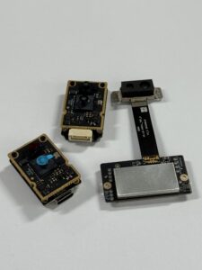
HM-LD1 with different interfaces and cables or not
Key Technical Attributes
- ⚙️ SPAD dToF Architecture: Employs a Single-Photon Avalanche Diode receiver designed for real-time, high-sensitivity 3D point cloud generation.
- ⚙️ Adapts to Indoor & Outdoor Conditions: Supports a 0.5m–25m range indoors and a 0.2m–8m range in bright outdoor sunlight (up to 80,000 lux).
- ⚙️ Ultra-Compact Profile: Measuring only 43.5mm × 30.0mm × 26.5mm (excluding protective outer housing variations which extend up to 43.5mm * 43.5mm * 28.5mm) and weighing just 28 grams, the module easily fits on lightweight drone gimbals or compact robotic frames.
- ⚙️ Flexible Integration Interfaces: Supports UART, UDP, and UVC plug-and-play connections, enabling fast integration across diverse embedded and PC platforms.
📄 Technical Documentation & Integration
Looking for mechanical CAD drawings, interface pinouts, or low-level register configurations? Get the technical documentation directly from the factory:
Detailed Specifications
Below is a detailed breakdown of the technical specifications for the HM-LD1 Solid-State LiDAR module:
View Product Details & Pricing ➔
5. Multi-Scenario Industrial Implementations & SLAM Integration
Integrating solid-state dToF technology is driving major improvements in autonomous navigation pipelines across the industrial and commercial sectors. Let’s look at how this plays out on the ground.
1. AGVs & AMRs: Precision SLAM & Obstacle Avoidance
Modern warehouse safety standards require dynamic path adjustments around unexpected obstructions, cardboard spills, and human workers. Traditional 2D planar safety scanners only detect objects at a single, fixed height (typically 10-15cm off the floor). This creates dangerous blind spots for low-hanging obstacles, overhead crane cables, or protruding forklift forks.
The HM-LD1 module addresses this vulnerability. System engineers can mount multiple HM-LD1 units on a robot’s corners to create an overlapping, wide-area detection field. Its 60° × 45° FOV captures physical details both near the floor and overhead. In addition, the parsed 3D point cloud streams directly into SLAM packages, such as Cartographer, RTAB-Map, or Hector SLAM, to generate real-time spatial maps. Instead of getting stuck on a stray pallet slat, the robot simply paths around it without skipping a beat.
2. Multi-Rotor UAV Platforms: Terrain Following & Soft Landing
Drones deployed for utility monitoring, pipeline inspections, or structural evaluations require continuous, high-accuracy relative altitude measurements to prevent ground collisions. Traditional barometric sensors drift with weather patterns, and ultrasonic altimeters fail over water or coarse vegetation.
The HM-LD1 offers a reliable solid-state solution. Weighing just 28g, it integrates onto micro-UAV frames without degrading overall flight times. Because it operates out to 25 meters indoors and 8 meters in direct sunlight, airborne flight controllers can utilize the module for precision terrain following, canopy mapping, and high-safety autonomous landing procedures. No drift, no acoustic interference—just reliable optical distance data.
3. Outdoor Autonomous Vehicles & Robotic Lawnmowers
The outdoor agricultural environment represents an engineering challenge for standard distance-ranging hardware. Heavy foliage, fine dust particles, direct sunlight reaching 80,000 lux, and uneven terrain easily disrupt passive camera sensors.
Using SPAD dToF technology, the HM-LD1 filters out high-intensity outdoor ambient solar noise, providing clean distance profiles down to ±3cm precision. These capabilities allow robotic lawnmowers to accurately detect the boundaries between grass and pavement, isolate debris in their path, and navigate complex pathways without depending on unstable GPS signals in suburban environments.
4. Perimeter Guarding, Volume Measurement & Logistics Control
Beyond mobile robotics, fixed-position solid-state arrays excel in security monitoring and material handling logistics. Placed over conveyor belts, the HM-LD1’s 3D point cloud continuously measures object volumes and box dimensions, allowing automated sorting systems to operate at high velocities. Additionally, its configurable zone-intrusion profiles make it a highly reliable sensor for safety-curtain zones around hazardous industrial machinery, shutting down power lines the fraction of a millisecond an operator crosses a safety plane.
6. Deep-Dive Engineering FAQ
How does LiDAR technology actually work, and is it better than cameras or radar?
Is LiDAR necessary for robotic mowers and AGVs, or can vision systems replace it?
What is the benefit of Solid-State dToF LiDAR over traditional mechanical LiDAR?
How do you integrate the HM-LD1 with software systems like ROS, Linux, or Windows?
📚 References & Further Reading
- Industry Standard: Learn more about high-performance industrial laser scanners and safety compliance paradigms at SICK Industrial Sensing Solutions.
- Solid-State Innovators: To research advancements in 3D solid-state camera chips and micro-pixel arrays, visit SOS LAB Technology.
- Related Product Guide: Read deep architectural specifications directly at the DTOF Solid State LiDAR HM-LD1 Product Hub.