What is RTK? The Ultimate Guide to Centimeter-Level GPS Navigation for Robots & UAVs
Look, if you are trying to guide an autonomous tractor down a crop row or land a multi-thousand-dollar mapping drone on a moving docking station, standard GPS is going to let you down. Your average smartphone or car navigation setup gets by just fine with a 3-to-5-meter margin of error because you only need to know roughly what lane or street you are on. In the world of industrial robotics and commercial drone fleets, that kind of error margin is not just sloppy—it is an absolute liability that leads to crashed rotors, damaged crops, and broken hardware.
The core problem comes down to physics. Standard Global Navigation Satellite Systems (GNSS) are constantly fighting a losing battle against the Earth’s atmosphere. By the time a high-frequency timing signal travels from a satellite orbiting 20,000 kilometers overhead down to your receiver, it has been bent, delayed, and scattered. It has fought its way through active ionospheric electron storms and variable tropospheric moisture layers. Add in satellite clock drift and raw signal reflections off metal structures—what we call multipath propagation—and your final coordinate calculation gets messy fast.
RTK, or Real-Time Kinematics, completely changes how we look at positioning. Instead of just reading the raw, noisy digital codes embedded in the satellite signals, RTK tracks the actual phase of the high-frequency carrier wave itself. This shifts the mathematical error margin from meters down to under two centimeters. It is the core technology behind automated flight paths, hands-free farming, and precision industrial layout work.
Getting this kind of accuracy up and running is not magic, but it does require a solid grasp of high-frequency physics, system architecture, and robust hardware integration. In this guide, we will break down the mechanics of carrier-phase tracking, compare how different frequency bands perform in the field, and show you how industrial modules like the HM-D20 and HM-D13 handle these extreme math problems in real-time under brutal outdoor conditions.
Table of Contents
- 👉 1. How RTK Works: From Carrier Phase to Centimeter Accuracy
- 👉 2. The Core Architecture: Base Stations, Rovers, and NTRIP
- 👉 3. Where Centimeter Precision Matters: Robots, UAVs, and Surveying
- 👉 4. Deep Dive: Helical Antenna RTK Module HM-D20 for UAVs
- 👉 5. Deep Dive: Multiband RTK Survey Module HM-D13 for Heavy-Duty Systems
- 👉 6. Comparative Analysis: HM-D20 vs. HM-D13 Technical Specifications
- 👉 7. Implementation & Technical FAQ
1. How RTK Works: From Carrier Phase to Centimeter Accuracy
To understand why RTK is such a massive upgrade, we have to look closely at how a basic GPS receiver works. Standard GPS relies on code-phase tracking. The satellites send down a pseudo-random noise (PRN) code—essentially a highly structured digital pattern of ones and zeroes modulated onto a carrier radio wave. Your receiver generates an identical pattern internally and shifts it in time until it perfectly matches the incoming signal. By measuring how much it had to shift that pattern, the receiver calculates the travel time and determines your distance from that satellite. Here is the catch: each bit of this code spans roughly 300 meters. Even with state-of-the-art algorithms resolving the code down to 1% of its width, your baseline measurement is still dirty, leaving you with an inherent error margin of several meters.
RTK throws this code-matching strategy out the window. Instead of waiting for these massive digital code chips, it directly tracks the raw sinusoidal carrier waves that transport them. Take the L1 frequency band, which operates around 1575.42 MHz. Its physical wavelength is incredibly tight—just 19 centimeters. By measuring the phase angle of this incoming wave—effectively tracking where the peak and trough of each wave cycle hits the antenna—the receiver can resolve spatial distances down to a fraction of a millimeter. It is like replacing a standard tape measure that only has markings every 300 meters with an ultra-precise digital caliper.
The Problem of Integer Ambiguity
While tracking carrier waves is incredibly precise, it introduces a tough mathematical challenge known as Integer Ambiguity. Your receiver can measure the exact fractional phase of the wave very reliably, but it has no way of immediately knowing the total number of complete wave cycles between the satellite and your antenna. Think of it like trying to measure the distance to a wall using a standard ruler: you can easily read the fractional millimeter mark where the ruler hits the wall, but if you do not know how many times the ruler has been laid end-to-end to get there, that fractional reading is useless. This relationship is defined by the core carrier-phase tracking equation:
Φ = ρ + c · (dt – dT) + λ · N – dion + dtrop + ε
Let us break down what is actually happening in this equation so we can see how the receiver cleans up the signal:
- Φ: The raw carrier phase measurement, expressed in physical meters.
- ρ: The true, uncorrupted geometric distance between the satellite and the receiver antenna.
- c: The speed of light in a vacuum, which serves as our baseline velocity constant.
- dt and dT: The clock synchronization errors of the receiver and the satellite, respectively. Even tiny nanosecond timing drift can throw coordinates off by meters.
- λ: The physical carrier wavelength (e.g., ~19 cm for the standard L1 frequency).
- N: The Integer Ambiguity value—the total number of complete wave cycles we need to find.
- dion and dtrop: The atmospheric delays caused by ionospheric refraction and tropospheric moisture layers.
- ε: The baseline system noise, which includes high-frequency thermal noise in the receiver circuitry and localized multipath reflections.
To solve for that elusive integer ambiguity (N), RTK uses a process called double-differencing. This technique relies on having two separate antennas observing the same set of satellites. By subtracting the phase measurements of one receiver from the other, and then subtracting the results between two different satellites, the system cancels out the satellite and receiver clock errors. Furthermore, because both antennas are relatively close on the ground, the signals travel through almost the same column of air, allowing us to drop the atmospheric delay terms (dion and dtrop) out of the equation entirely.
Once the system strips away these major sources of error, it uses advanced search algorithms—most notably the LAMBDA (Least-squares Ambiguity Decorrelation Adjustment) method—to nail down the exact integer value of N. During this initialization period, the system moves through two distinct operating states:
- Float Solution: During this startup phase, the algorithms are still calculating the integer ambiguity. The system has to treat N as a floating-point decimal value. While this still gets you closer than standard standalone GPS, your positioning margin remains in the sub-meter range, which is not quite ready for high-precision autonomous work.
- Fixed Solution: Once the mathematical search resolves the precise integer values of N, the ambiguity is locked down as a fixed whole number. The system instantly transitions into an RTK Fixed state, dropping your positioning margin to centimeter-level accuracy. Achieving this fix quickly requires tracking multiple frequency bands from different satellite constellations.
This phase-comparison process is highly effective and shares a lot of foundational physics with other industrial measurement techniques, such as the optical phase and frequency analysis used in high-end Time of Flight (ToF) systems, but scaled up to work with orbital platforms.
2. The Core Architecture: Base Stations, Rovers, and NTRIP
An RTK receiver cannot find its centimeter-level position on its own. It operates as part of a real-time data loop that requires three hardware elements to work together simultaneously.
1. The Base Station
The Base Station is positioned at a fixed, highly accurate coordinate location. Because the base station knows its exact physical coordinates, it measures incoming satellite signals and compares its calculated phase measurements with its known position. Any discrepancies it finds are the local atmospheric, orbital, and clock errors. The base station bundles these correction values into a continuous stream of real-time correction messages.
2. The Rover
The Rover is the mobile receiver mounted directly on your autonomous vehicle, drone, or mapping rig. It tracks the same overhead satellites as the base station. By itself, the rover faces the same atmospheric delays, but as soon as it receives the correction stream from the base station, it applies those values to its own carrier phase readings, instantly eliminating the shared atmospheric and clock errors.
3. The Communication Link
To transmit these corrections in real time, the base station packages the data into a standard protocol called RTCM (Radio Technical Commission for Maritime Services). This data stream is typically sent to the rover using one of two methods:
- ⚙️ Local UHF/VHF Radios: In this setup, your base station connects directly to an industrial radio transmitter, broadcasting RTCM updates over licensed or license-free RF bands (usually 433 MHz or 915 MHz). This is the best approach for remote farms, open-pit mines, or marine channels where cellular networks are unreliable or unavailable.
- ⚙️ NTRIP Casters: This method uses a cellular internet connection instead of a local radio. The rover connects to an internet server called an NTRIP (Networked Transport of RTCM via Internet Protocol) caster. This caster streams correction data from a wide network of permanent, land-based base stations—often called CORS (Continuously Operating Reference Stations). It is incredibly convenient because is eliminates the need to set up your own base station on-site, though you are dependent on reliable local cellular coverage.
3. Where Centimeter Precision Matters: Robots, UAVs, and Surveying
Moving from standard 3-meter GPS to high-rate RTK positioning has transformed how many industrial platforms operate, making automation practical in demanding environments.
Unmanned Aerial Vehicles (UAVs) & Inspection Drones
When you are flying a multirotors drone close to high-voltage power lines, bridge piers, or offshore wind turbine blades, wind shifts and sensor drift can lead to a costly crash. RTK gives the flight controller the stability it needs to hover within millimeters of its target. In mapping and surveying, RTK tags every aerial photo with centimeter-grade coordinate metadata. This eliminates the need for field crews to spend hours laying out and surveying physical Ground Control Points (GCPs) across the site, saving substantial field time.
Autonomous Ground Robotics & Precision Agriculture
In modern farming, autonomous tractor steering systems use multi-constellation RTK to plant, fertilize, and spray along high-precision paths with less than two centimeters of shift from pass to pass. This level of precision reduces ground compaction, prevents chemical overspray, and keeps input costs down. For urban delivery robots and robotic lawnmowers, RTK provides the reliable lane-level accuracy needed to keeps wheels safely on paths and sidewalks, preventing them from drifting into streets or landscaping.
For more challenging environments where satellite signals can be completely blocked—such as under dense forest canopies, inside warehouse bays, or in indoor industrial halls—engineers often combine RTK with optical and LiDAR fusion suites. To see how these integrated perception systems handle complex navigation challenges when GPS is not an option, take a look at Domi Sensor’s industrial array of perception and ranging hardware.
4. Deep Dive: Helical Antenna RTK Module HM-D20 for UAVs
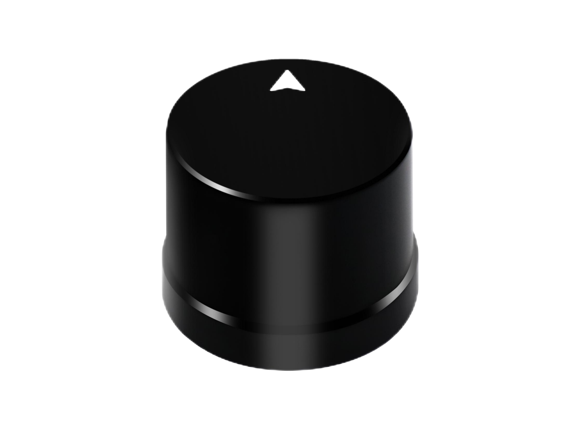
The Helical Antenna RTK Module HM-D20 is a compact, lightweight receiver designed specifically for weight-sensitive aerial platforms where every gram affects flight time and battery life.
Integrated Quad-Arm Helical Design
Unlike standard GPS modules that use flat ceramic patch antennas, the HM-D20 features an integrated quad-arm helical antenna. Traditional patch antennas require a wide flat ground plane beneath them to block out-of-phase signals bouncing off the ground. Helical antennas use a specialized three-dimensional winding structure that provides omnidirectional, high-gain signal tracking. This allows them to maintain a solid lock on low-elevation satellites near the horizon, even when a drone is banking sharply or fighting high crosswinds. This integrated design eliminates the need for heavy ground planes, keeping wind resistance and weight to an absolute minimum.
Multi-Frequency, Multi-Constellation Engine
The HM-D20 is built around an advanced GNSS engine that tracks multiple frequency bands across all major global satellite constellations:
- ✅ GPS: L1 and L5 bands
- ✅ BeiDou: B1, B2A, and B2I bands
- ✅ GLONASS: G1 band
- ✅ Galileo: E1 and E5 bands
- ✅ QZSS: L1 and L5 bands
- ✅ IRNSS: L5 band
Tracking both L1 and L5 frequencies simultaneously allows the HM-D20 to calculate and remove ionospheric delays internally. This dual-frequency tracking drastically reduces your Time to First Fix (TTFF) and ensures a reliable RTK Lock even when operating around dense foliage or urban canyons.
Ruggedized Construction and Interface
The HM-D20 is built for real-world field conditions. Its compact casing carries an IP67 waterproof and dustproof rating, protecting its sensitive electronics from heavy rain, humidity, and fine dust. The module features a straightforward TTL-level UART interface set to a standard 115200 bps baud rate. This makes it easy to integrate with open-source flight controllers like Pixhawk running PX4 or ArduPilot, as well as ROS-driven embedded computers like Jetson boards.
Helical Antenna RTK Module HM-D20 Specifications
| Parameter Group | Technical Specification Details |
|---|---|
| Frequency band | GPS L1/L5, BeiDou B1/B2A/B2I, GLONASS G1, Galileo E1/E5, QZSS L1/L5, IRNSS L5 |
| RTK position accuracy | Horizontal: 1cm + 1ppm, Vertical: 1.5cm + 1ppm |
| Protocol | NMEA 0183 output and RTCM input at rover side |
| Baud Rate | 115200 bps |
| Dimensions | Φ44 * 37 mm |
| Timing synchronization accuracy | 20ns |
| L1 and L5 GNSS antenna system | At least 40db high gain |
| Interface | TTL level UART interface |
| Operating Temperature | -40 °C to 85 °C |
| Waterproof Rating | IP67 |
5. Deep Dive: Multiband RTK Survey Module HM-D13 for Heavy-Duty Systems
For heavy-duty ground platforms, survey rigs, and agricultural equipment where weight is less critical than absolute durability and signal gain, the Multiband RTK Survey Module HM-D13 is a highly reliable option.

Optimized Mushroom Dome Design
The HM-D13 features a rugged domestic dome housing. This shape accommodates a wide-aperture patch antenna element paired with a large internal ground shield. This configuration provides exceptional multipath mitigation, filtering out signals reflected from metal buildings, damp soil, or passing vehicles. The housing is made from heavy-duty UV-stabilized polycarbonate, engineered to withstand cracking, fading, and weathering during long-term exposure to intense sunlight and extreme temperatures ranging from -40°C to +85°C.
Flexible Base and Rover Modes
A key advantage of the HM-D13 is its design flexibility. While the smaller HM-D20 is primarily built to act as a mobile rover, the HM-D13 can be configured as either an RTK Rover or an RTK Base Station. In Base Station mode, the module runs a self-survey routine to establish its geographic coordinates, then shifts into broadcast mode, outputting high-accuracy RTCM v3 updates via its physical serial port to your transmission system.
Advanced Connectivity Options
The HM-D13 handles all major constellations, tracking GPS, BeiDou, Galileo, GLONASS, QZSS, and IRNSS bands simultaneously. Its larger housing can accommodate an optional internal 4G LTE communication module, allowing it to connect directly to the internet for NTRIP data casting without needing an external cellular modem. Weighing under 550 grams, it is light enough for portable survey setups but tough enough to handle the high vibrations of heavy earthmovers and agricultural tractors.
Multiband RTK Survey Module HM-D13 Specifications
| Parameter Group | Technical Specification Details |
|---|---|
| Frequency band | GPS L1/L5, Beidou B1/B2A/B2I, Galileo E1/E5, QZSS L1/L5, GLONASS G1, IRNSS |
| RTK position accuracy | Horizontal: 1cm + 1ppm, Vertical: 1.5cm + 1ppm |
| Protocol | NMEA 0183 output and RTCM input at rover side. RTCM output at base side. |
| Baud Rate | 115200 bps |
| Dimensions | Φ152 * 67.9 mm |
| Weight | < 550 g |
| Interface | TTL level UART interface |
| Timing synchronization accuracy | 20ns |
| Operating Temperature | -40 °C to 85 °C |
| Additional Hardware Options | Supports 4G radio module (Optional) |
6. Comparative Analysis: HM-D20 vs. HM-D13 Technical Specifications
Choosing the right module comes down to understanding your platform’s specific weight limits, environment, and physical layout. The comparison table below highlights the key differences between these two industrial systems:
| Feature / Specification | Helical Antenna RTK Module HM-D20 | Multiband RTK Survey Module HM-D13 |
|---|---|---|
| Physical Form Factor | Compact Quad-Helix Cylinder Array | Wide-Plate “Mushroom” Dome Structure |
| Target Applications | Weight-sensitive UAVs, lightweight drones, aerial inspection rigs | Precision farming tractors, heavy machinery, base stations, ground surveying |
| Dimensions | Φ44 * 37 mm | Φ152 * 67.9 mm |
| Weight | Ultra-lightweight (< 100g) | Robust/Heavy duty (< 550g) |
| Operating Temperature Range | -40 °C to 85 °C | -40 °C to 85 °C |
| Dual Base & Rover Role | Configured primarily as high-sensitivity Rover | Software switchable between Base Station & Rover modes |
| Structural Case & Durability | IP67 Waterproof protection | Weatherproof & UV-Resistant Polycarbonate housing |
| Expanded Hardware Slots | None (Integrated all-in-one logic) | Supports optional internal 4G radio module |
Three Core Advantages — Elevating Perception Capability
7. Implementation & Technical FAQ
Does the positioning data coordinate represent the physical RTK module, or is it isolated to the antenna’s phase center?
Can satellite coordinate data be integrated into customized target software platforms?
Where is the positioning data stored inside an RTK ecosystem — base station or rover?
What is the physical output interface of the base station: TTL or RS232?
How do I connect and configure the HM-D20 or HM-D13 to a standard Pixhawk or PX4 flight controller?
GPS1 or GPS2 port. Every module ships with a compatible JST-GH connector cable to simplify the wiring.Next, hook up to your ground station software, like QGroundControl or Mission Planner, and adjust your serial port settings: set the baud rate on that serial port to 115200 bps and set the GPS driver protocol to auto-configure. The flight controller will communicate with the module, request the necessary NMEA/UBX messages, and inject the incoming RTCM correction packets directly into the stream, bringing your system to an RTK Fixed lock.