Drone Obstacle Avoidance: How to Choose Reliable LiDAR Sensing for Safer UAV Autonomy
Modern drones can fly faster, farther, and with a lot less hand-holding than they could a few years ago. But here’s the deal: one weak perception layer can still turn a capable UAV into an expensive pile of carbon fiber. Power lines, tree branches, warehouse racks, walls, scaffolding, bridge structures, low-texture surfaces, and bad lighting all give basic vision systems a hard time. For industrial UAVs, drone obstacle avoidance is not a flashy add-on. It is a safety-critical autonomy function that protects the aircraft, the payload, nearby workers, and the mission schedule.
Reliable obstacle avoidance is not as simple as bolting a sensor to the frame and calling it done. Engineers have to look at detection range, field of view, frame rate, weight, power draw, outdoor performance, vibration, data interface, SDK support, and how the flight controller turns sensor data into real braking, hovering, rerouting, or terrain-following behavior. This guide walks through how drone obstacle avoidance works, compares the main sensing technologies, and explains how compact dToF solid-state LiDAR modules such as the DTOF Solid State LiDAR HM-LD1 can support near-field distance detection, depth mapping, terrain following, and safer UAV autonomy.
Table of Contents
- 👉 What Is Drone Obstacle Avoidance?
- 👉 Why Obstacle Avoidance Matters for UAV Autonomy
- 👉 How Drone Obstacle Avoidance Works
- 👉 Drone Obstacle Avoidance Sensor Technologies Compared
- 👉 Why LiDAR Is Valuable for Drone Obstacle Avoidance
- 👉 How to Choose a LiDAR Sensor for Drone Obstacle Avoidance
- 👉 Recommended dToF LiDAR Module: DTOF Solid State LiDAR HM-LD1
- 👉 Integration Workflow for UAV Developers
- 👉 Flight Controller, ROS, and Embedded Software Considerations
- 👉 Common Failure Modes in Drone Obstacle Avoidance
- 👉 Industrial Applications for Drone Obstacle Avoidance
- 👉 Engineering Checklist: Choosing Drone Obstacle Avoidance LiDAR
- 👉 Final Thoughts: Building Safer UAV Autonomy with Reliable Depth Sensing
- 👉 FAQ: Drone Obstacle Avoidance
What Is Drone Obstacle Avoidance?
Drone obstacle avoidance is the full sensing-and-control process that allows an unmanned aerial vehicle to detect nearby hazards, estimate their distance and position, and change its flight behavior before contact happens. Look, in a real engineering environment, obstacle avoidance is not just a sensor spec on a datasheet. It is a chain that starts with hardware, continues through filtering and software, and ends with the flight controller making a safe physical move.
Sharing a compact dToF sensor we’ve been working with for drone obstacle av…
Obstacle Detection vs Obstacle Avoidance
Obstacle detection means the drone or companion computer can tell that something exists in the flight path. That detection may come from a LiDAR distance reading, a depth image, a 3D point cloud, stereo disparity, radar return, ultrasonic range value, or fused perception layer. Obstacle avoidance goes further. It means the UAV actually slows down, stops, hovers, backs away, climbs, descends, reroutes, or maintains a safe standoff distance based on that detection.
This distinction matters in the shop and in the field. A drone can technically “see” a wall and still fly right into it if the data is not passed to the flight controller correctly, if the coordinate frame is wrong, if the thresholds are too tight, or if the aircraft is moving faster than the avoidance loop can handle. A real UAV obstacle detection system has to be validated at the system level, not just on a bench with a sensor pointed at a cardboard box.
Reactive Avoidance vs Planned Autonomous Navigation
Reactive avoidance is short-horizon behavior. For example, if a forward-facing sensor reports that the center zone is inside a safety threshold, the drone can brake or hover. Planned autonomous navigation is broader. It uses maps, waypoints, costmaps, localization, and route planning to avoid hazards before they become immediate threats. Industrial UAVs usually need both: planned navigation for the mission and reactive drone collision avoidance as the last line of defense.
Near-Field vs Long-Range Obstacle Perception
Near-field perception is especially important for inspection drones, indoor UAVs, research platforms, and slow autonomous systems. This is where drones hit racks, walls, beams, ceilings, cables, and structural surfaces. Long-range perception matters more for high-speed outdoor flight, where the drone eats up distance quickly and needs more time to brake. The right sensing architecture depends on aircraft speed, payload limits, operating environment, and acceptable risk.
Why Obstacle Avoidance Matters for UAV Autonomy
As drones move from manual aerial photography into industrial inspection, warehouse automation, infrastructure monitoring, security patrol, agriculture, and robotics research, obstacle avoidance becomes a core reliability requirement. A professional UAV may carry expensive cameras, thermal imagers, mapping equipment, radios, or custom payloads. A collision can destroy the airframe, wreck the payload, stop operations, and create safety problems for workers or bystanders.
From Pilot Assistance to Full Autonomy
In pilot-assist applications, obstacle avoidance acts like a safety buffer when an operator misjudges distance, loses orientation, or gets distracted by the camera feed. In autonomous missions, the need is even stronger because the UAV may be following preplanned waypoints without constant human correction. Repeatable perception lets the drone react when the real site does not match the map, such as when a forklift moves in a warehouse or temporary scaffolding appears near a bridge.
Industrial Risk: Payload Damage, Downtime, and Safety
Industrial drones often work near bridges, expressways, dams, power facilities, storage tanks, warehouses, and confined spaces. These sites have hard surfaces, complex geometry, poor GPS availability, lighting variation, wind, vibration, and obstacles that are hard to model ahead of time. Near-field LiDAR obstacle avoidance gives the UAV measurable distance data so the control system can slow, stop, or maintain standoff distance before the aircraft gets too close.
Why Near-Field Sensing Is Often the Critical Layer
Many industrial collisions do not happen because the mission plan is terrible. They happen in the final few meters. The drone drifts in wind, enters a GPS-denied zone, moves too close to a wall, or gets pulled into a tight inspection angle. A compact depth sensor for UAV applications can provide real-time distance data right where the risk is highest. When comparing depth-sensing options, engineers should also understand how structured light differs from time-of-flight methods. For a deeper explanation, learn how phase works in 3D structured light cameras.
How Drone Obstacle Avoidance Works
A practical drone obstacle avoidance system runs as a continuous loop: sense the environment, process the data, represent obstacle risk, make a decision, send a command, and repeat. The quality of that loop depends on sensor accuracy, frame rate, latency, mounting, filtering, and how well perception is tied into real flight behavior.
Step 1: Sensing the Environment
The sensing layer may use LiDAR, dToF sensors, stereo vision, monocular cameras, ultrasonic sensors, radar, optical flow, or a combination of these. A dToF LiDAR module measures distance by emitting light and measuring return timing. A stereo camera estimates depth from differences between two images. Radar measures reflected radio waves. Each technology has tradeoffs, which is why professional UAV perception systems often use sensor fusion instead of betting everything on one input.
Step 2: Converting Raw Data into Depth or Obstacle Zones
Raw data has to become something the drone can use. A depth image may be divided into left, center, right, upper, and lower regions. A point cloud can be transformed into a 3D obstacle layer. A single range value can define a stop condition. For a forward-facing LiDAR, developers might calculate the nearest valid distance in the central region of interest and use that value to trigger speed reduction or braking.
Step 3: Triggering Avoidance Behavior
Early avoidance behavior should be simple and conservative. A good first approach is to slow the drone when the forward distance is less than a warning threshold and stop or back away when the distance is below a hard threshold. More advanced systems can choose a clear direction, sidestep, climb, descend, or reroute around an obstacle using a local planner.
Step 4: Closing the Control Loop
Frame rate and latency matter. If a drone is flying at 2 m/s and the perception system updates at 10 fps, a new frame arrives about every 0.1 seconds. The drone moves roughly 0.2 m between frames before processing delay, communication delay, flight-controller reaction, and motor response are included. That is why range, safety margin, and speed limits must be engineered together.
Drone Obstacle Avoidance Sensor Technologies Compared
There is no universal best sensor for every UAV. A drone obstacle detection sensor must match the mission environment, speed, payload budget, compute resources, and required autonomy level. Here is how the common options stack up in real work.
LiDAR Sensors
LiDAR provides direct distance measurement and can generate depth maps or point clouds. It is useful in low-texture scenes where visual systems may struggle, such as blank walls, industrial surfaces, tunnels, or poorly lit areas. Compact solid-state LiDAR modules are attractive for UAVs because they reduce mechanical complexity and payload weight compared with larger scanning systems.
dToF Time-of-Flight Sensors
dToF means direct time-of-flight. The sensor estimates distance by measuring how long emitted light takes to return from a target. SPAD-based dToF modules are designed for sensitive photon detection and can provide real-time depth data in compact packages. For drones, dToF LiDAR can support forward obstacle sensing, downward altitude hold, terrain following, and robotic perception development.
Stereo Vision Cameras
Stereo vision provides rich visual information and can support SLAM, visual odometry, and scene understanding. The catch is that stereo systems can struggle in low light, glare, repetitive patterns, and textureless areas. They also need careful calibration and enough compute power to calculate disparity reliably.
Monocular Vision and AI Cameras
Monocular AI cameras are lightweight and useful for object classification, tracking, and semantic perception. But estimating reliable metric depth from one camera is difficult without motion, training data, or known scale references. For safety-critical collision avoidance, they are usually stronger when paired with a real distance sensor.
Ultrasonic Sensors
Ultrasonic sensors are low cost and simple, often used for landing or short-range altitude detection. Their limitations include narrow effective range, sensitivity to surface angle, airflow, acoustic noise, and soft materials that absorb sound.
Millimeter-Wave Radar
Millimeter-wave radar can be robust in dust, fog, and some poor-weather conditions. It may also provide velocity information. The tradeoff is lower spatial resolution compared with LiDAR or cameras. Radar is useful in harsh environments, especially when fused with optical sensors.
Sensor Fusion for Reliable UAV Perception
Many professional UAVs combine multiple technologies. LiDAR provides direct distance, cameras provide scene context, radar improves harsh-environment robustness, and GNSS/IMU systems provide positioning and motion estimation. For UAVs that also require precise positioning, obstacle avoidance is often combined with GNSS, RTK, inertial navigation, and perception sensors. Positioning technology suppliers such as Unicore Communications show how navigation-grade components complement onboard perception.
| Sensor Type | Strengths | Limitations | Best Use Cases |
|---|---|---|---|
| LiDAR / dToF LiDAR | Direct distance measurement, useful for depth maps and point clouds, less dependent on texture | Range and outdoor performance depend on optical design, sunlight, reflectivity, and power | Obstacle detection, altitude hold, terrain following, robotics perception |
| Stereo Vision | Rich visual information, passive sensing, useful for SLAM and object recognition | Can struggle in low light, repetitive patterns, textureless walls, and glare | Navigation, mapping, visual odometry, scene understanding |
| Monocular AI Camera | Lightweight, low cost, supports semantic detection | Depth estimation may be less reliable without scale reference or training data | Object classification, tracking, pilot assistance |
| Ultrasonic | Low cost, simple, good for short-range landing assistance | Narrow range, affected by soft materials, angle, airflow, and acoustic noise | Landing, indoor altitude sensing, very short-range detection |
| Millimeter-Wave Radar | Robust in dust, fog, and some weather conditions | Lower spatial resolution than cameras or LiDAR; integration complexity | Outdoor safety, velocity detection, harsh environments |
Why LiDAR Is Valuable for Drone Obstacle Avoidance
LiDAR is valuable because it measures distance directly. Instead of trying to infer depth only from image texture or learned visual patterns, LiDAR returns range data that can be converted into obstacle zones. That makes it practical for UAV inspection, indoor navigation, terrain following, and autonomous robotics that need to operate near real structures.
Direct Distance Measurement
A LiDAR sensor gives the system measurable distance information. This matters when the flight controller needs to decide whether to brake, hover, or hold a standoff distance from a wall, beam, rack, tree, or ground surface. Direct range data also makes early algorithms easier because developers can set thresholds in meters instead of trying to interpret visual confidence scores.
Depth Maps and Point Clouds for UAV Perception
A depth image is a grid of distance values. A point cloud is a 3D spatial representation of measured points. For a drone, these outputs can identify blocked regions, estimate surface distance, build local maps, or feed ROS perception pipelines. A 40 × 30 depth grid, for example, can support zone-based obstacle detection even if it is not meant for detailed object recognition.
Low-Light and Textureless Scene Advantages
Vision-only systems often struggle when there is little texture, sudden lighting change, glare, or repetitive patterns. LiDAR does not depend on visible texture the same way. That is useful around concrete walls, painted surfaces, ceilings, tunnels, storage areas, and industrial structures.
Solid-State LiDAR vs Mechanical Scanning LiDAR
Mechanical scanning LiDAR can provide broad coverage, but it often adds size, weight, moving parts, cost, and integration complexity. Solid-state LiDAR modules are usually more compact and easier to integrate into small UAVs. For drones where every gram affects endurance and stability, compact solid-state sensing is a practical option for directional obstacle detection.
Where LiDAR Still Needs Careful Engineering
LiDAR is useful, but it is not magic. Outdoor range can be reduced by sunlight. Dark or low-reflectivity surfaces may return weaker signals. Highly reflective materials can create artifacts. The field of view has to match the flight risk, and the control loop has to react in time. Engineers should evaluate LiDAR based on UAV speed, braking distance, mounting direction, and expected obstacle types.
How to Choose a LiDAR Sensor for Drone Obstacle Avoidance
Choosing a LiDAR sensor for drone obstacle avoidance is an engineering decision, not just a purchasing decision. The best module is the one that fits the aircraft’s speed, environment, control architecture, payload budget, and safety margin.
1. Detection Range: Indoor, Outdoor, and Real-World Margins
Detection range must be evaluated in the actual operating environment. Indoor or nighttime range is often longer than outdoor daytime range because ambient sunlight affects optical sensing. A sensor with an 8 m outdoor daytime range may be suitable for controlled-speed inspection or near-field obstacle zones, while high-speed UAVs may need longer-range sensing or sensor fusion.
2. Field of View: Matching Sensor Coverage to Flight Risk
Horizontal FOV helps detect lateral hazards during yaw, drift, and path correction. Vertical FOV helps with branches, slopes, ground, ceilings, and obstacles above or below the centerline. A narrow FOV can miss side hazards, while a wide FOV still needs enough spatial resolution to be useful.
3. Resolution: How Much Spatial Detail Is Enough?
Resolution affects how much shape information the system receives. For simple zone-based avoidance, modest depth resolution can be enough. For object classification or detailed mapping, higher resolution or camera fusion may be required. Do not overbuy resolution if the control logic only needs reliable distance zones.
4. Frame Rate and Latency
Frame rate determines how often the perception system updates. A 10 fps sensor provides a new frame about every 100 ms. That can work for slow or medium-speed inspection drones when paired with conservative thresholds. Faster UAVs need longer detection range, higher frame rate, lower latency, or stricter speed limits.
5. Weight and Size for UAV Payload Budgets
Every gram affects flight time, maneuverability, and airframe design. A compact 28 g LiDAR module is easier to mount on small UAVs than a larger sensor assembly. Size also affects aerodynamic placement and whether the sensor can be positioned without propeller, landing gear, or payload occlusion.
6. Power Consumption and Thermal Design
Low power consumption helps preserve battery endurance and simplifies thermal design. A 1.2 W module has a lower impact than higher-power perception assemblies, but it still needs a stable power supply, proper wiring, and clean integration.
7. Interface Options: UART, UDP, and UVC
UART is useful for embedded communication and simple flight-controller-oriented integration. UDP is practical for networked data transfer to embedded computers. UVC provides a camera-like USB video class workflow for PCs and Linux systems. Interface flexibility lowers development risk because teams can prototype on one platform and deploy on another.
8. SDK and Platform Support
Development teams should confirm SDK availability early. For HM-LD1 integration, see the DTOF SSL HM-LD1 SDK guide for platform support and development workflow. SDK availability for x86 Windows, x86 Linux, and ARM Linux is useful for teams working across PCs, Raspberry Pi, Jetson-style systems, and custom Linux controllers.
9. Environmental Adaptability
Temperature range, lighting conditions, dust, vibration, and target reflectivity all affect real-world performance. Industrial drone teams should test in representative conditions instead of relying only on laboratory specifications.
10. Mechanical Mounting and Vibration
Mounting affects data quality and safety. The LiDAR should be rigidly aligned, protected from propeller occlusion, isolated from excessive vibration, and calibrated to the drone coordinate frame. Misalignment can make the flight controller treat a forward obstacle as a side obstacle or misread ground distance.
Recommended dToF LiDAR Module: DTOF Solid State LiDAR HM-LD1
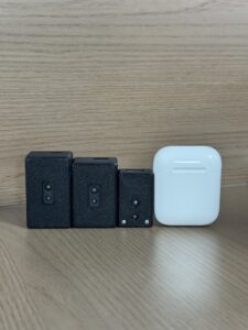
The DTOF Solid State LiDAR HM-LD1 is a compact SPAD dToF LiDAR module designed to deliver real-time depth images and 3D point cloud data for environmental perception. With a lightweight 28 g design, 60° horizontal × 45° vertical field of view, multiple data interfaces, and support for embedded platforms, it is suitable for UAV obstacle avoidance, altitude hold, terrain following, robot navigation, SLAM assistance, smart inspection, and robotic vision development.
HM-LD1 is especially relevant for UAV developers who need a compact drone distance sensor for near-field depth perception. Its specifications support controlled-speed obstacle detection, downward ranging, indoor altitude hold, terrain following, and experimental autonomous drone navigation. It can also be used in robotic systems, cameras, security systems, presence detection, object recognition experiments, volume measurement, and zone intrusion monitoring.

View Product Details & Pricing ➔
| Specification | DTOF Solid State LiDAR HM-LD1 |
|---|---|
| Product Name | DTOF Solid State LiDAR HM-LD1 |
| Technology | SPAD dToF solid-state LiDAR |
| Dimensions | 43.5 mm × 30 mm × 26.5 mm |
| Weight | 28 g |
| Ranging Capability | Indoor: 0.5–25 m; Outdoor: 0.2–8 m |
| Ranging Accuracy | ±3 cm |
| Field of View | 60° horizontal × 45° vertical |
| Resolution | 40 × 30 |
| Frame Rate | 10 fps |
| Interfaces | UART / UDP / UVC |
| Operating Temperature | -20 ℃ to 60 ℃ |
| Power Consumption | 1.2 W |
| Supported Development Platforms | x86 Windows, x86 Linux, ARM Linux |
| Typical Applications | Drone obstacle avoidance, UAV altitude hold, terrain following, robot navigation, SLAM assistance, distance detection, smart inspection, robotic vision development |
| Product Page | View HM-LD1 Product Details |
| Product Brochure | DTOF SSL HM-LD1 Product Brochure |
Why HM-LD1 Fits UAV Obstacle Avoidance
The HM-LD1 weighs 28 g, which matters because payload mass directly affects endurance, flight distance, and stability. Its 1.2 W power consumption helps limit battery and thermal impact. The 60° × 45° field of view can support forward-facing obstacle perception or downward-facing ranging. With 10 fps depth updates, it can support controlled near-field operation when flight speed and avoidance thresholds are designed properly.
Best-Fit UAV Use Cases
Best-fit applications include forward-facing obstacle detection for slow inspection drones, downward terrain following, indoor altitude hold, structure inspection near walls or bridge components, warehouse UAV development, and research platforms using Raspberry Pi, embedded Linux, or companion computers. The module’s UART, UDP, and UVC interfaces let developers choose a communication setup that fits the prototype and the final aircraft.
Engineering Limitations to Consider
Use the HM-LD1 within realistic assumptions. Outdoor daytime range is listed as 0.2–8 m, so high-speed drones may require additional long-range sensing or strict speed limits. The 40 × 30 resolution is suitable for depth perception and obstacle-zone detection, but not high-detail object recognition. The 10 fps frame rate requires latency-aware control logic and conservative safety margins. Mounting, calibration, and filtering are not optional.
Integration Workflow for UAV Developers
Integrating LiDAR into a drone takes a structured workflow. The goal is to move from raw range data to safe flight behavior without pretending that detection automatically means avoidance.
Step 1: Define the Avoidance Requirement
⚙️ Start by defining the operational requirement. Is the drone avoiding frontal obstacles, maintaining altitude, following terrain, flying indoors, flying outdoors, or inspecting structures at close range? What is the maximum speed? What is the minimum safe stopping distance? Those answers determine range, field of view, frame rate, and control behavior.
Step 2: Select Sensor Mounting Direction
⚙️ A forward-facing mount supports collision avoidance during forward flight. A downward-facing mount supports altitude hold, landing assistance, and terrain following. Side-facing sensors can support wall-following or inspection. Multi-sensor layouts may be required for broader coverage, but each added sensor increases weight, power draw, processing load, and calibration work.
Step 3: Choose the Data Interface
⚙️ UART can support simple embedded communication. UDP is practical for networked embedded computers. UVC is useful for USB-based depth image workflows. During bench testing, teams may separate sensor and host hardware or experiment with data links. For robotics experiments, this UART wireless bridge guide can help developers understand practical wireless UART data transmission concepts.
Step 4: Read Depth Data or Point Cloud Output
⚙️ After communication is established, validate raw sensor output before connecting it to flight behavior. Display the depth frame or point cloud, move known objects through the field of view, and confirm measured distance. This avoids trying to debug flight behavior while the underlying sensor data is still misunderstood.
Step 5: Create Obstacle Zones
⚙️ Divide the depth frame into regions of interest, such as left, center, right, upper, and lower zones. Filter invalid pixels, apply median filtering or region averaging, and ignore regions that contain the drone frame, landing gear, or prop guards. Obstacle zones make it easier to turn sensor data into simple control decisions.
Step 6: Connect Perception to Flight Control Logic
⚙️ Begin with conservative logic. If the center zone distance is below a warning threshold, reduce speed. If it is below a stop threshold, brake or hover. If the left zone is blocked and the right zone is clear, sidestep right only after validating that the flight controller supports that behavior safely. Downward ranging can adjust altitude when terrain distance changes.
Step 7: Test in Controlled Environments
⚙️ Start with static bench tests, then tethered or low-altitude tests, then slow indoor flight with soft obstacles or safe barriers. Log raw sensor data, obstacle messages, flight commands, and vehicle response. Controlled testing reveals latency, blind spots, mounting errors, and threshold mistakes before outdoor deployment.
Step 8: Expand to Outdoor and Mission-Specific Testing
⚙️ Outdoor tests should include bright sunlight, shadows, dark surfaces, reflective objects, different approach angles, vibration, wind, and realistic flight speeds. Mission-specific validation is essential because a sensor that works in a lab may behave differently near concrete bridges, metallic structures, glass, vegetation, or dusty industrial sites.
Flight Controller, ROS, and Embedded Software Considerations
Sensor integration is only one part of drone obstacle avoidance. The perception output must be accepted by the flight stack and transformed into safe behavior. This often requires a flight controller, companion computer, middleware, coordinate transforms, and carefully tuned thresholds.
Flight Controller Integration
ArduPilot- or PX4-style architectures typically require obstacle distance messages, rangefinder inputs, or companion computer integration. The exact method depends on the flight stack, firmware version, and avoidance mode. Engineers should verify that avoidance is enabled, that the correct sensor orientation is configured, and that the flight controller receives timely data.
ROS and ROS 2 Perception Pipelines
ROS and ROS 2 can process depth images and point clouds into costmaps, obstacle layers, and local planning inputs. They are powerful for development, but they also require good timestamping, frame transforms, and compute management. A bad transform tree can make the drone react in the wrong direction, and that is the kind of mistake that looks small on a laptop but gets expensive in the air.
Raspberry Pi, Jetson, and Embedded Linux
Companion computers such as Raspberry Pi, Jetson, and other embedded Linux systems can handle filtering, visualization, sensor fusion, and higher-level decision-making. Developers should profile CPU usage, memory usage, and communication latency because perception workloads can compete with navigation, logging, and telemetry tasks.
Obstacle Zones, Costmaps, and Safety Margins
Avoidance zones should consider drone size, propeller radius, payload extension, GPS/IMU uncertainty, wind drift, braking distance, and sensor latency. The obstacle threshold should not be set right at the physical collision distance. It needs enough margin for the drone to react safely.
Latency, Synchronization, and Timestamping
Timestamping is important when fusing LiDAR data with IMU, odometry, visual data, or GNSS. If the drone is moving, old sensor data may describe where an obstacle was relative to the aircraft several moments ago. For slow inspection flight, this may be manageable. For faster flight, poor synchronization can cause late or incorrect reactions.
Common Failure Modes in Drone Obstacle Avoidance
Troubleshooting drone obstacle avoidance means looking at the complete chain from sensor measurement to aircraft response. Most failures are not caused by one bad component. They are caused by mismatched assumptions between sensor range, software, mounting, flight speed, and control behavior.
The Sensor Detects the Obstacle, but the Drone Does Not Avoid It
This often means the sensor output is not correctly connected to the flight stack. Causes include wrong coordinate frames, disabled avoidance parameters, incorrect message formats, thresholds set too close, or companion computer delay. Fixes include validating raw sensor data, visualizing depth output, checking flight-controller parameters, logging obstacle messages, and testing with a stationary obstacle before flight.
The Drone Avoids Too Late
Late avoidance is usually caused by insufficient detection range, excessive flight speed, low update rate, high processing latency, or underestimated braking distance. The answer may be to reduce speed, increase avoidance thresholds, simplify processing, add longer-range sensing, or fuse multiple sensors.
False Positives Cause Unstable Flight
False positives may come from reflections, sunlight, dust, rain, propeller occlusion, landing gear, cables, or invalid depth pixels. Filtering, better mounting, confidence thresholds, temporal smoothing, and stable regions of interest can reduce unstable behavior. Do not make the aircraft react aggressively to one noisy measurement.
Outdoor Range Is Shorter Than Expected
Optical depth sensors are affected by sunlight and target reflectivity. Bright outdoor conditions can reduce effective range, especially on dark or low-reflectivity targets. Test the sensor under real mission lighting and add margin instead of relying only on best-case indoor range.
Blind Spots Around the Drone
A single sensor only covers its field of view. A forward-facing LiDAR does not protect the rear, sides, or overhead region. Full-direction obstacle avoidance requires multiple sensors, sensor fusion, or mission constraints that prevent movement into unobserved space.
Vibration, Mounting, and Calibration Problems
Vibration can degrade sensor data or loosen alignment. Mounting angle errors can shift obstacle position in the control frame. Calibration should include known-distance tests and verification that the reported obstacle direction matches the drone coordinate system.
Industrial Applications for Drone Obstacle Avoidance
Industrial UAVs operate in environments where human pilots may not have a clear view and where GPS or visual texture may be limited. Drone obstacle avoidance improves mission reliability by giving the aircraft local awareness near structures and terrain.
Bridge and Infrastructure Inspection
Bridge inspection drones encounter beams, cables, pillars, uneven surfaces, and GPS-denied spaces. LiDAR depth data helps measure standoff distance and supports near-field obstacle zones, especially around low-texture concrete or steel structures.
Warehouse and Indoor Inventory Drones
Indoor warehouses contain racks, shelves, forklifts, walls, ceilings, and poor lighting. A compact UAV LiDAR sensor can provide direct ranging where stereo vision may struggle with repetitive shelf patterns or low light.
Power Line and Utility Inspection
Utility environments include poles, cables, towers, and vegetation. Thin obstacles can be difficult, so LiDAR should be combined with careful flight planning, cameras, and conservative speed limits. Avoidance systems should not be assumed to detect every wire in every condition.
Dam, Expressway, and Large Structure Inspection
Large structures often require close standoff inspection. dToF LiDAR can help the drone maintain distance from walls, surfaces, and structural edges. Outdoor sunlight testing is essential because real conditions vary significantly across time of day and surface type.
Security Patrol and Zone Monitoring
Security drones may fly around buildings, fences, corridors, and restricted zones. Obstacle detection supports safer patrol paths and can also contribute to zone awareness when fused with cameras or other perception sensors.
Agriculture and Terrain Following
Agricultural drones may need to maintain height above crops or terrain. Downward LiDAR can support terrain following, but vegetation reflectivity, movement, and uneven canopy height must be considered during testing.
Research, Education, and Prototype UAVs
Universities, student teams, and robotics developers often need a practical way to test UAV perception without building a complete vision pipeline from scratch. A compact dToF LiDAR module with multiple interfaces and SDK support can accelerate prototype development.
Engineering Checklist: Choosing Drone Obstacle Avoidance LiDAR
Before selecting a LiDAR obstacle avoidance sensor, engineering teams should answer the following questions. In the shop, this checklist helps keep the conversation tied to real flight safety instead of spec-sheet bragging.
- ✅ What is the drone’s maximum operating speed during obstacle avoidance?
- ✅ What stopping distance is required at that speed?
- ✅ Is the UAV operating indoors, outdoors, or both?
- ✅ What is the minimum and maximum detection range required?
- ✅ Does the sensor provide direct distance, depth map, or point cloud data?
- ✅ Is the field of view wide enough for the flight path?
- ✅ Is the resolution sufficient for obstacle-zone detection?
- ✅ Is the frame rate suitable for the control loop?
- ✅ Can the airframe support the sensor’s weight and size?
- ✅ Is the power consumption acceptable for the drone battery budget?
- ✅ Does the interface match the flight controller or companion computer?
- ✅ Are SDKs available for the development platform?
- ✅ Can the sensor operate in the expected temperature range?
- ✅ Has the sensor been tested under real lighting conditions?
- ✅ How will the system handle false positives and invalid depth data?
- ✅ What happens if the sensor fails during flight?
- ✅ Will the system need one sensor or multiple sensors for coverage?
- ✅ Can the LiDAR be fused with cameras, IMU, GNSS, or radar?
If your UAV project requires compact depth sensing for obstacle avoidance, altitude hold, or robotic perception, explore the DTOF Solid State LiDAR HM-LD1 or contact the engineering team for integration support.
Final Thoughts: Building Safer UAV Autonomy with Reliable Depth Sensing
Drone obstacle avoidance is a system-level function. It depends on the right sensor, correct mounting, reliable data processing, validated control logic, and realistic safety margins. A LiDAR sensor can provide direct depth information that is valuable for UAV obstacle avoidance, altitude hold, terrain following, inspection, and robotic perception, but it must be matched to the drone’s speed, environment, and flight behavior.
Compact dToF solid-state LiDAR is especially practical for prototypes, inspection drones, embedded UAV platforms, and robots where size, weight, power, and interface flexibility matter. The HM-LD1 offers a lightweight 28 g design, 1.2 W power consumption, 60° × 45° field of view, 40 × 30 resolution, 10 fps frame rate, UART/UDP/UVC interfaces, and SDK support for x86 Windows, x86 Linux, and ARM Linux.
To evaluate compact dToF sensing for your UAV or robotics platform, view the DTOF Solid State LiDAR HM-LD1 or download the product brochure for detailed integration planning.
FAQ: Drone Obstacle Avoidance
Is drone obstacle avoidance actually effective, or is it just a premium feature?
What is a low-cost obstacle avoidance setup for a student or prototype drone project?
Why does my drone detect obstacles but still fail to evade them?
Is LiDAR better than a camera for drone obstacle avoidance?
How much detection range does a drone need for obstacle avoidance?
Can one LiDAR sensor provide full drone obstacle avoidance?
What field of view is suitable for drone obstacle avoidance?
What frame rate is needed for UAV obstacle avoidance?
Can drone obstacle avoidance work outdoors in sunlight?
How should LiDAR be mounted on a drone?
📚 References & Further Reading
- Industry Standard: Unicore Communications
- Related Guide: DTOF SSL HM-LD1 SDK guide