Avoid Drone Collisions with Compact dToF LiDAR: Smarter UAV Obstacle Detection for Safer Autonomous Flight
For UAV manufacturers, robotics integrators, and industrial drone operators, the ability to avoid drone collisions is not a nice-to-have anymore. Here’s the deal: if a drone is flying near bridges, power infrastructure, warehouse racks, crop rows, buildings, cranes, vehicles, or people, one missed obstacle can turn a clean mission into broken hardware, downtime, liability, or a safety incident. Cameras can struggle when the scene has poor texture or bad lighting. Ultrasonic sensors are useful, but they run out of range fast. GPS can tell a drone where it is on a map, but it will not tell the aircraft that a beam, branch, wall edge, or forklift is sitting right in the flight path.
That is why modern UAV systems need real-time depth perception. A drone has to measure the space around it, not just estimate it. It needs enough information to detect obstacles, hold altitude, follow terrain, maintain inspection standoff, and make safe path corrections before the aircraft gets into trouble. In the shop, we usually separate the problem into two parts: first, the drone has to see the obstacle; second, the controller has to do something sensible with that information.
Compact solid-state dToF LiDAR gives UAV developers a practical way to add that sensing layer without bolting a heavy, power-hungry perception payload onto the aircraft. The DTOF Solid State LiDAR HM-LD1 provides depth maps and 3D point cloud data in a lightweight 28 g module, with a 60° × 45° field of view, ±3 cm ranging accuracy, and UART / UDP / UVC interfaces for embedded development. That combination matters when you are trying to build a drone that is light enough to fly efficiently but still smart enough to understand what is nearby.
This guide explains how dToF LiDAR helps drones detect trees, walls, structures, terrain, equipment, racks, and nearby objects. It also shows where compact LiDAR fits into UAV collision avoidance, autonomous navigation, terrain following, altitude hold, and industrial inspection workflows. Look, no sensor makes a drone magically safe by itself. But a well-integrated depth sensor gives the flight stack real distance data, and that is a big step toward safer autonomous flight.
Table of Contents
- 👉 Why Drone Collision Avoidance Matters
- 👉 What Is Drone Obstacle Detection?
- 👉 How dToF LiDAR Works for UAV Perception
- 👉 LiDAR vs Camera vs Ultrasonic vs Radar for Drone Collision Avoidance
- 👉 Industrial UAV Use Cases for Obstacle Avoidance
- 👉 DTOF Solid State LiDAR HM-LD1 for UAV Obstacle Detection
- 👉 How to Integrate Compact LiDAR into a Drone
- 👉 Obstacle Avoidance Logic and Flight Control
- 👉 Environmental Performance and Design Limits
- 👉 Buyer Checklist for UAV LiDAR Modules
- 👉 Build Safer UAV Obstacle Detection with Compact dToF LiDAR
- 👉 FAQ: Avoid Drone Collisions with dToF LiDAR
Why Drone Collision Avoidance Matters
The phrase “avoid drone” can point to two real engineering concerns. One is helping a drone avoid obstacles and collisions during flight. The other is reducing unsafe drone operation around people, property, machinery, and infrastructure. In both cases, the root issue is the same: the UAV needs reliable environmental awareness. A drone cannot avoid what it cannot perceive, and navigation data alone will not reveal a cable, wall edge, roofline, beam, branch, vehicle, or person entering the aircraft’s path.
Drone collisions happen because UAVs work in dynamic three-dimensional environments. Open sky is forgiving. Industrial sites are not. A drone may fly perfectly in a test field and then become vulnerable when it moves close to bridges, roofs, utility poles, warehouse racks, cranes, trees, tunnels, towers, or confined structures. Manual piloting also gets less reliable when visibility is poor, the inspection route is repetitive, the pilot is watching through a compressed video feed, or the aircraft is far enough away that depth perception becomes guesswork.
GPS is useful for global positioning, but it is not an obstacle detector. It does not identify nearby walls, moving forklifts, poles, wires, people, roof edges, or other UAVs. A barometer estimates altitude, but it does not measure distance to local terrain changes. An IMU tells you how the aircraft is moving, not what it is about to hit. For collision avoidance, the drone needs perception sensors that measure the physical environment in real time and turn that measurement into useful information for a controller or companion computer.
This is why UAV collision avoidance matters so much in industrial inspection, agricultural surveying, warehouse inventory drones, public safety UAVs, mapping, security patrol, and infrastructure monitoring. These aircraft often fly close to expensive assets or in areas where a crash interrupts operations. For a broader overview of UAV sensing strategies, see our related drone obstacle avoidance guide.
From an engineering standpoint, collision avoidance is not just a sensor purchase. It is a system reliability problem. You have to consider sensor range, field of view, frame rate, processing latency, mechanical mounting, payload weight, power budget, flight speed, braking distance, control behavior, and field validation. Compact dToF LiDAR helps because it measures distance directly and provides a structured depth map that is easier to convert into safety zones than a single-point distance value.
What Is Drone Obstacle Detection?
Drone obstacle detection is the perception stage of a collision avoidance system. It is the process of sensing objects around the UAV, estimating their distance or position, and passing that information to the flight control logic. Detection does not automatically mean avoidance. That second stage requires interpreting the data and commanding the drone to slow down, stop, hover, climb, descend, yaw, translate, or reroute.
Obstacle Detection vs Obstacle Avoidance
Detection means the UAV senses that an object is present and estimates where it is relative to the aircraft. The output may be a distance value, depth map, point cloud, occupancy grid, warning flag, or object zone. Avoidance means the aircraft uses that data to change motion. For example, a forward-facing LiDAR module may detect an obstacle three meters ahead. The avoidance algorithm then decides whether three meters is safe at the current speed. If the answer is no, the controller may reduce speed, stop, hover, or choose a new path.
That distinction matters. A high-quality sensor alone does not guarantee safe flight. The control system has to be tuned to the aircraft. A larger drone moving quickly needs more detection range and braking distance than a small inspection drone creeping along a bridge surface. Sensor latency, data filtering, motor response, payload mass, wind, and propeller wash all affect the final avoidance behavior.
What a Drone Needs to Detect
A UAV may need to detect many obstacle types depending on its mission. Common examples include trees and branches, walls, poles, power lines, cables, other UAVs, terrain height changes, people, vehicles, beams, pipes, warehouse racks, roof edges, tower structures, and industrial equipment. Some targets are large and easy to detect. Others, such as thin wires, dark materials, angled surfaces, or small branches, are harder and require careful testing.
In many collision scenarios, the drone does not need to classify the object before reacting. It does not always need to know whether the object is a tree, wall, machine, or vehicle. The immediate safety question is simpler: is something inside the safety envelope? If an obstacle enters the warning zone, the UAV can slow down. If it enters the emergency zone, the UAV can stop or hover. Identification is useful for advanced autonomy, but direct depth perception is often the quickest route to practical collision reduction.
Real-Time Depth Perception
Real-time depth perception gives a drone a spatial understanding of the environment. A depth map contains distance measurements across a field of view. A point cloud represents measured points in three-dimensional space. Field of view tells you how much of the scene the sensor can see. Range tells you the minimum and maximum distance over which the sensor can measure. Frame rate tells you how often the UAV receives updated depth information. Accuracy describes measurement precision, while latency describes how long it takes for sensor data to become available to the control system.
Those variables combine into a practical safety envelope. A 10 fps depth sensor updates ten times per second. At slow inspection speeds, that can be enough for short-to-medium range obstacle awareness. The system can divide the depth map into left, center, right, upper, and lower zones, track the closest object in each zone, and choose a response. For more robust systems, sensor fusion may combine LiDAR with cameras, IMU data, optical flow, GPS, RTK, radar, or ultrasonic sensors.
How dToF LiDAR Works for UAV Perception
LiDAR, short for light detection and ranging, measures distance using emitted light; in a direct time-of-flight system, the sensor calculates range from the travel time of reflected photons. For general background, see LiDAR and time-of-flight. In UAV obstacle detection, the practical value is straightforward: LiDAR provides direct distance information instead of relying only on visual interpretation.
Direct Time-of-Flight Measurement
In a direct time-of-flight measurement, the sensor emits light pulses toward the environment. When those pulses hit a surface, part of the light reflects back to the receiver. The sensor detects the returning photons and calculates distance based on the travel time of the light. Because light travels extremely fast, the system depends on precise timing electronics and sensitive detection. The result is a distance measurement that can be used to create a depth frame.
For drones, dToF is attractive because the output is immediately tied to range. A flight computer can process the nearest points in the forward direction, compare them with configured thresholds, and decide whether the UAV has enough clearance. That is different from monocular vision, where distance may need to be inferred from motion, scale, trained models, or scene assumptions.
Solid-State LiDAR for Drones
Solid-state LiDAR is especially suitable for compact UAVs because it avoids bulky rotating mechanical assemblies. Drones vibrate. They accelerate. They operate in changing temperatures. They have limited payload space and limited battery capacity. A compact solid-state module is easier to mount into the drone body, a forward sensor bay, a downward sensor bay, or a small protective housing. Reduced mechanical complexity also makes product design easier for manufacturers that need repeatable assembly and stable field performance.
SPAD-Based Depth Sensing
The HM-LD1 is based on SPAD dToF technology. SPAD stands for single-photon avalanche diode. In plain language, a SPAD detector can respond to very low levels of returning light, which is important when the module has to stay compact and power-efficient. This enables the module to produce real-time depth images and 3D point cloud data for environmental perception.
In a UAV system, SPAD-based dToF sensing can support front obstacle detection, downward altitude measurement, terrain following, landing awareness, robot vision, and short-to-medium range navigation. Final performance depends on lighting, surface reflectivity, distance, sensor orientation, mounting, and software filtering. Still, the basic measurement principle gives engineers a solid foundation for practical collision avoidance.
From Depth Map to Flight Decision
The perception pipeline starts when the LiDAR captures a depth frame. An embedded system, development board, PC, or companion computer receives the distance matrix or point cloud through an interface such as UART, UDP, or UVC. Software filters invalid points, removes outliers, and identifies objects inside warning zones. Once the system decides an object is too close, it sends a command or warning to the flight controller. Depending on the mission and aircraft dynamics, the drone may slow down, stop, hover, climb, descend, yaw away, or pause the autonomous mission.
This conversion from depth data to flight action is where engineering discipline matters. Thresholds should not be chosen only from sensor accuracy. You also have to account for drone speed, stopping distance, control loop rate, data latency, wind, vibration, propeller wash, and the cost of false positives or false negatives. For inspection drones operating near expensive infrastructure, conservative safety margins are usually the right call.
LiDAR vs Camera vs Ultrasonic vs Radar for Drone Collision Avoidance
Commercial buyers often compare LiDAR, camera, ultrasonic, and radar sensors when designing UAV collision avoidance. Each sensing technology has strengths and limitations. The best choice depends on the drone’s size, speed, environment, autonomy level, payload budget, processing capability, and mission risk.
| Sensor Type | Strengths | Limitations | Best UAV Use Cases |
|---|---|---|---|
| dToF LiDAR | Direct distance measurement, depth map output, compact modules, strong for obstacle detection | Range and performance depend on target reflectivity and ambient light conditions | Obstacle avoidance, altitude hold, terrain following, inspection drones |
| Camera / Stereo Vision | Rich visual information, object classification, low hardware cost | Needs lighting and texture; depth estimation can be computationally heavy | Visual navigation, recognition, mapping, AI perception |
| Ultrasonic | Low cost, simple short-range distance measurement | Short range, wide beam, affected by airflow and surface angle | Landing assist, indoor low-speed proximity detection |
| Radar | Works in fog, dust, and poor visibility; good for velocity measurement | Lower spatial resolution than LiDAR in many compact systems | Longer-range detection, adverse weather UAVs, speed sensing |
Why LiDAR Is Useful When Distance Is the Main Variable
LiDAR is useful when the main question is distance. In many avoid-drone-collision scenarios, the aircraft does not need full visual classification before reacting. It needs to know whether something is inside the planned path and how much clearance remains. A dToF LiDAR depth map gives the control system range values across the field of view, allowing the UAV to detect obstacles in front, below, or beside the aircraft.
Why Sensor Fusion Still Matters
Look, LiDAR should not be sold as the only answer to UAV safety. Robust drones often use sensor fusion. Cameras provide visual context and object classification. IMUs provide motion state. GPS and RTK provide global position. Barometers estimate altitude. Optical flow supports low-altitude motion estimation. Radar or ultrasonic sensors may help in specific conditions. LiDAR adds direct depth measurement, which can reduce dependence on visual texture and improve the reliability of short-to-medium range obstacle detection.
Where Compact dToF LiDAR Fits Best
Compact dToF LiDAR fits especially well in forward obstacle detection, downward altitude hold, side proximity sensing, landing zone awareness, and short-to-medium range autonomous navigation. A forward-facing module can monitor objects entering the flight path. A downward-facing module can help maintain a consistent distance from terrain or industrial surfaces. Side-facing modules can support wall following or confined-space inspection. Multi-sensor layouts can improve coverage where the drone needs broader situational awareness.
Industrial UAV Use Cases for Obstacle Avoidance
Industrial UAVs often fly closer to obstacles than consumer drones. They inspect assets, scan inventory, survey terrain, monitor perimeters, and operate in GPS-denied environments. In these jobs, the ability to avoid drone crashes directly affects mission success, asset protection, and operator confidence.
Infrastructure Inspection
Infrastructure inspection drones work near bridges, expressways, dams, towers, roofs, pipelines, and confined structures. These environments include surfaces that are difficult or dangerous for people to approach. A compact LiDAR module can help the UAV maintain a safe standoff distance while collecting inspection data. The HM-LD1 product details note that outdoor ranging can support accurate measurement from 8 meters on a clear summer day, assuming approximately 80,000 lux. That makes it useful for short-to-medium distance measurements in outdoor inspection tasks where the drone is moving at controlled speeds.
Warehouse and Indoor Drones
Indoor drones operate in spaces where GPS may be unavailable or unreliable. Warehouses, factories, tunnels, logistics centers, and large industrial buildings require local perception. Indoor drones may perform inventory scanning, rack inspection, aisle patrol, safety monitoring, or asset tracking. The HM-LD1 supports indoor ranging from 0.5 m to 25 m, providing useful depth data for controlled indoor flight. Because indoor scenes often include walls, racks, doors, beams, pallets, columns, and equipment, a depth map can be converted into obstacle zones for safer navigation.
Agricultural and Terrain-Following Drones
Agricultural drones benefit from distance sensing when flying near crops, trees, terrain changes, poles, and irrigation structures. Downward LiDAR can help maintain a consistent height above the canopy or ground. That matters for spraying uniformity, imaging consistency, and terrain-following missions. Forward or side sensing may also help detect orchard rows, tree lines, posts, and unexpected obstacles. In agricultural use, engineers should consider dust, sunlight, vegetation reflectivity, and drone speed when setting safety thresholds.
Security and Patrol UAVs
Security and patrol UAVs may operate near buildings, fences, people, vehicles, and restricted zones. A collision avoidance sensor supports safer perimeter patrol, zone intrusion monitoring, people or object proximity detection, and operation near structures. In these missions, the drone may fly repetitive routes, so reliable depth sensing can reduce the risk of route-following errors and operator fatigue. LiDAR data can also support awareness when the drone approaches walls, gates, or building edges.
Robotics Beyond UAVs
The same depth perception principles apply beyond drones. Mobile robots, inspection platforms, smart cameras, and security systems can use dToF LiDAR for distance detection, object recognition assistance, user presence detection, volume measurement, zone intrusion monitoring, and SLAM development. For teams developing broader robotics systems, MRP also provides navigation-related solutions such as Robobaton; developers can also review the Robobaton Mini tutorial for related integration concepts.
DTOF Solid State LiDAR HM-LD1 for UAV Obstacle Detection
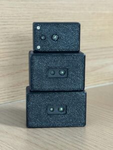
The DTOF Solid State LiDAR HM-LD1 is a compact SPAD dToF LiDAR module designed to output real-time depth images and 3D point cloud data. For UAV developers, its compact housing, 28 g weight, low 1.2 W power consumption, and UART / UDP / UVC interfaces make it suitable for prototyping and embedded deployment in drone obstacle avoidance, altitude hold, terrain following, autonomous navigation, distance detection, inspection, and robotic vision systems.
HM-LD1 supports indoor ranging from 0.5 m to 25 m and outdoor ranging from 0.2 m to 8 m. Product details also describe 0–25 m ranging in indoor or nighttime conditions and 0–8 m in outdoor daytime environments. Its 40 × 30 resolution gives the host system a grid of depth measurements, while the 60° horizontal × 45° vertical field of view helps cover a practical frontal or downward sensing area. The module can display ranging measurement data as point cloud and depth data, which is valuable for software teams building zone detection, obstacle filtering, and navigation functions.
MRP offers SDKs for x86 Windows, x86 Linux, and ARM Linux, enabling development and integration across diverse operating systems and architectures. This is particularly useful for teams moving from PC-based evaluation to embedded deployment on Linux robotics platforms, Raspberry Pi-class systems, or companion computers connected to flight controllers. You can also Download the DTOF SSL HM-LD1 Product Brochure for product documentation.
| DTOF Solid State LiDAR HM-LD1 Specifications | |
|---|---|
| Product Name | DTOF Solid State LiDAR HM-LD1 |
| Product URL | https://myrobotproject.com/product/dtof-solid-state-lidar-hm-ld1/ |
| Dimension | 43.5 mm × 30 mm × 26.5 mm |
| Ranging Capability | Indoor: 0.5–25 m; Outdoor: 0.2–8 m |
| Ranging Accuracy | ±3 cm |
| Field of View | 60° horizontal × 45° vertical |
| Weight | 28 g |
| Resolution | 40 × 30 |
| Frame Rate | 10 fps |
| Interface | UART / UDP / UVC |
| Operating Temperature | -20 ℃ to 60 ℃ |
| Power Consumption | 1.2 W |
| SDK Support | x86 Windows, x86 Linux, ARM Linux |
| Primary Outputs | Real-time depth images and 3D point cloud data |
| Typical Applications | UAV obstacle avoidance, altitude hold, terrain following, autonomous navigation, robot vision, inspection, distance detection, SLAM development |
View Product Details & Pricing ➔
Why 28 g Matters for Drone Design
Every gram matters in UAV design. Payload weight affects flight time, motor selection, battery sizing, thermal behavior, and mission endurance. A 28 g sensor is easier to integrate into smaller airframes than a larger perception payload. For industrial drone manufacturers, low sensor weight reduces the tradeoff between safety features and mission payload. For inspection drones, it helps preserve flight time while still adding active depth perception.
Why 60° × 45° FOV Matters
The HM-LD1 field of view is 60° horizontal × 45° vertical. A wider field of view improves near-field awareness because the sensor observes more than a narrow centerline. In a forward-facing configuration, this helps detect objects entering the flight path from the side or appearing above and below the centerline. In a downward-facing configuration, the field of view can help monitor terrain variation and surface changes below the aircraft. Engineers should still consider placement angle, mounting height, speed, and the required safety envelope.
Why UART / UDP / UVC Interfaces Matter
Interface flexibility reduces integration risk. UART is useful for embedded controllers and straightforward serial communication. UDP is useful for networked systems and embedded computers that process data over Ethernet-style communication. UVC is useful for camera-like streaming to PCs and development boards, which can speed up prototyping in vision software environments. Because HM-LD1 supports UART, UDP, and UVC, developers can integrate it with PCs, Raspberry Pi, flight controller companion systems, and embedded platforms more easily than if only one interface were available.
How to Integrate Compact LiDAR into a Drone
Integrating compact LiDAR into a drone requires mechanical, electrical, software, and control-system planning. A good workflow starts with the mission requirement, not the sensor. Engineers should define what the aircraft must avoid, how quickly it flies, what directions need coverage, and what response is acceptable when an obstacle is detected.
Step 1 — Define the Collision Avoidance Direction
⚙️ A forward-facing module is used for frontal collision avoidance. It is appropriate for drones flying toward walls, trees, racks, bridges, buildings, or inspection targets. A downward-facing module supports altitude hold, landing awareness, and terrain following. Side-facing modules can support wall following, aisle navigation, and confined-space inspection. Multi-sensor configurations can provide broader awareness when the mission requires coverage in multiple directions. The direction should match the highest-risk movement of the drone.
Step 2 — Choose the Interface
⚙️ Interface choice depends on the onboard architecture. UART may be appropriate for simple embedded communication. UDP may be used when the sensor connects to a networked embedded computer. UVC can be convenient when the developer wants camera-like streaming into a PC or Linux vision stack. The HM-LD1’s SDK support for x86 Windows, x86 Linux, and ARM Linux makes it suitable for PC evaluation, Raspberry Pi development, Jetson-class embedded systems, and Linux robotics stacks.
Step 3 — Mount the Sensor Rigidly
⚙️ Mechanical mounting has a major effect on perception quality. The sensor should be mounted rigidly to reduce vibration and maintain a stable coordinate relationship with the UAV body frame. The field of view should remain unobstructed by landing gear, propellers, arms, wires, payloads, or protective housings. Engineers should avoid frame shadowing, reflective parts near the lens, and positions where propeller wash may introduce contamination or vibration. The sensor coordinate frame should be aligned and calibrated relative to the drone body frame so the software correctly interprets obstacle direction.
Step 4 — Process Depth Data
⚙️ Depth processing converts raw measurements into useful navigation information. A common approach is to divide the depth map into zones such as left, center, right, upper, and lower regions. The software can calculate the closest valid object in each zone, filter invalid or noisy measurements, and compare the result with warning and emergency thresholds. More advanced systems may perform clustering, temporal filtering, point cloud transformation, or integration with mapping and SLAM algorithms.
Step 5 — Send Commands to Flight Controller
⚙️ After an obstacle is detected, the companion computer or control logic must communicate with the flight controller. Possible responses include slowing down, stopping, hovering, climbing, descending, yawing away, translating laterally, triggering return-to-home, pausing the mission, or following terrain at a safe distance. The response should be predictable and tested. For industrial drones, overly aggressive avoidance can be as problematic as late avoidance, especially near structures where sudden movement may create a new collision risk.

Obstacle Avoidance Logic and Flight Control
Obstacle avoidance logic transforms sensor data into safe motion. This layer must account for aircraft behavior, sensor characteristics, mission priorities, and operating environment. A compact LiDAR module provides depth data, but the control strategy determines whether that data results in safer flight.
Basic Safety-Zone Logic
A practical approach is safety-zone logic. In a green zone, the path is clear and the UAV continues the mission. In a yellow zone, an object is within a caution distance, so the drone slows down or prepares to reroute. In a red zone, the object is too close, so the drone stops, hovers, climbs, descends, or pauses the mission. These zones should be defined using flight speed, braking distance, processing delay, communication delay, and a reserve safety margin.
Depth Map Grid Interpretation
With 40 × 30 resolution, the HM-LD1 provides a grid of distance measurements across the field of view rather than only one single distance value. This allows the system to evaluate depth distribution across the scene. If the center region is blocked but the left region is clear, the drone may choose a lateral or yaw movement. If the lower region shows an approaching surface, the drone may adjust altitude. If all regions show nearby obstacles, stopping or hovering may be the safest response.
Example Decision Flow
A typical decision flow starts by checking the center safety zone because that region corresponds to the direct flight path. If the center distance is below the emergency threshold, the drone stops or hovers. If the center is blocked but one side is clear, the drone may yaw or translate toward the clear side. If the path is clear, the drone continues the mission. This logic should be implemented with filtering and hysteresis to avoid rapid oscillation caused by noise or momentary measurements.
Terrain Following and Altitude Hold
In a downward-facing installation, LiDAR supports local distance-to-ground measurement. This is different from barometric altitude because it measures the actual surface below the drone. Terrain following uses this local distance to maintain a desired height over slopes, uneven surfaces, crop canopies, roofs, roads, or industrial assets. Altitude hold can improve landing consistency, inspection standoff, and agricultural spray height. Engineers should account for surface angle, reflectivity, vibration, and airflow when tuning downward distance control.
Limitations of Automatic Avoidance
Automatic avoidance has real design limits. Avoidance depends on speed, braking distance, control loop latency, sensor update rate, and aircraft dynamics. Very thin objects such as wires, cables, and small branches may require sensor fusion and careful validation. Outdoor performance depends on lighting, reflectivity, weather, and operating distance. UAV testing must include real-world validation, staged risk reduction, safe test zones, and emergency procedures. LiDAR improves awareness, but it should be integrated as part of a complete safety architecture.
Environmental Performance and Design Limits
Sensor performance is always environment-dependent. Engineers should evaluate LiDAR range, accuracy, stability, and detection reliability under the same conditions expected in the actual mission. The HM-LD1 provides strong specifications for a compact module, but final UAV behavior must be validated with representative targets, flight speeds, lighting conditions, and mounting conditions.
Indoor and Nighttime Range
The HM-LD1 specifies indoor ranging from 0.5 m to 25 m. Product details also describe 0–25 m ranging in indoor or nighttime conditions. This makes it a strong fit for warehouses, tunnels, indoor inspection, logistics centers, factories, and GPS-denied environments. Indoor scenes often contain measurable surfaces such as walls, racks, doors, columns, beams, and equipment. Controlled lighting and lower ambient sunlight can also support stable ranging conditions.
Outdoor Daytime Range
The HM-LD1 specifies outdoor ranging from 0.2 m to 8 m. Product details also mention accurate measurement from 8 m on a clear summer day, assuming approximately 80,000 lux. This outdoor capability supports short-to-medium range UAV collision avoidance and industrial inspection tasks. Engineers should match flight speed to available detection range. A slow inspection drone can often operate safely with shorter detection distance than a fast-moving UAV that needs more stopping distance.
Accuracy and Control Margin
The module specifies ±3 cm ranging accuracy. That is useful for distance detection, altitude hold, and controlled standoff applications. However, control systems should use safety margins larger than raw sensor accuracy. A UAV is moving, vibrating, and responding to wind. Processing and communication delays also consume distance. If an obstacle threshold is set too close to the physical collision point, even an accurate sensor may not provide enough time for avoidance. Industrial designs should use conservative margins and validate them during flight tests.
Temperature and Power
The HM-LD1 operates from -20 ℃ to 60 ℃ and consumes 1.2 W. Low power consumption matters because UAVs are battery-powered systems where every watt affects endurance and thermal design. A low-power sensor also reduces heat management requirements in compact airframes. Temperature range is important for outdoor inspection, warehouse operation, and field robotics where equipment may operate in cold mornings, hot sunlight, or enclosed industrial spaces.
What Engineers Should Test Before Deployment
Before deployment, engineers should test reflective targets, dark objects, outdoor sunlight, indoor lighting, flight speed, vibration, dust, fog, rain if relevant, different approach angles, and mission-specific obstacle types. Testing should include the actual mounting location and aircraft motion because bench performance does not always translate directly to flight performance. Validation should also include false positive behavior, false negative risk, emergency stop response, and interaction with the mission planner.
Buyer Checklist for UAV LiDAR Modules
When selecting a LiDAR module to avoid drone crashes, buyers should compare the sensor against the complete aircraft requirement. A module that works well in a lab may not be ideal if it is too heavy, too power-hungry, too narrow in field of view, unsupported on the target platform, or difficult to mount on the airframe.
- ✅ Is the module light enough for the target UAV payload?
- ✅ Does the range match the drone’s speed and braking distance?
- ✅ Is the field of view wide enough for the desired safety zone?
- ✅ Does the module provide depth map or point cloud data?
- ✅ Are UART, UDP, or UVC interfaces supported?
- ✅ Are SDKs available for the target platform?
- ✅ Can the sensor operate in the required temperature range?
- ✅ Is power consumption suitable for battery operation?
- ✅ Has performance been tested under indoor and outdoor lighting?
- ✅ Can the supplier provide technical support for integration?
The HM-LD1 fits many of these criteria for compact UAV and robotics development. It weighs 28 g, consumes 1.2 W, provides a 60° × 45° field of view, specifies ±3 cm ranging accuracy, outputs 40 × 30 depth data at 10 fps, supports UART / UDP / UVC interfaces, and offers SDK support for x86 Windows, x86 Linux, and ARM Linux. MRP specializes in perception and positioning modules for robots and UAVs, with technical support services for product integration and application development.
Build Safer UAV Obstacle Detection with Compact dToF LiDAR
To avoid drone collisions, UAVs need more than GPS navigation and pilot skill. They need real-time perception that can detect nearby objects, measure distance, and support safe control decisions. Compact dToF LiDAR gives developers a practical sensing layer for obstacle detection, altitude hold, terrain following, landing awareness, inspection standoff, and robotic vision development. The HM-LD1 combines lightweight mechanical design, low power consumption, real-time depth output, and flexible interfaces in a module suitable for UAV and robotics integration.
Here’s the deal: safer autonomous flight is not built from one flashy feature. It comes from dependable sensing, conservative control margins, solid mounting, tested software, and field validation. A compact LiDAR module like HM-LD1 gives drone teams a practical depth-perception building block they can integrate into real aircraft without overloading payload, power, or development complexity.
Explore the DTOF Solid State LiDAR HM-LD1 for compact UAV obstacle detection, or download the HM-LD1 product brochure for detailed specifications.
Sharing a compact dToF sensor we’ve been working with for drone obstacle av…
FAQ: Avoid Drone Collisions with dToF LiDAR
How can drones detect and avoid obstacles such as trees, power lines, or other drones mid-air?
What type of sensor is best for building a drone collision avoidance system?
How can drone manufacturers reduce nuisance flights, crashes, and unsafe operation near people or property?
Can compact dToF LiDAR help a drone avoid obstacles indoors?
Is dToF LiDAR suitable for outdoor drone obstacle avoidance?
How does LiDAR support drone altitude hold and terrain following?
What does 40 × 30 LiDAR resolution mean for UAV obstacle detection?
Why are UART, UDP, and UVC interfaces important for drone developers?
Can LiDAR detect power lines or very thin obstacles?
How much LiDAR range does a drone need to avoid collisions?
📚 References & Further Reading
- Industry Standard: LiDAR and time-of-flight
- Related Guide: drone obstacle avoidance guide