Obstacle Sensing Robot Solutions: Choosing LiDAR, Depth Vision, and SLAM Sensors for Reliable Avoidance
An obstacle sensing robot is only as dependable as the perception hardware and software sitting behind it. Here’s the deal: you can have a beautiful chassis, a strong drive system, and a polished user interface, but if the robot cannot see a pallet, a person, a cable, a chair leg, or a forklift fork in time, the whole machine becomes a shop-floor problem. Whether the platform is an indoor service robot, warehouse AMR, inspection drone, security patrol robot, or autonomous research vehicle, reliable obstacle avoidance starts with one practical requirement: detect the object early enough, accurately enough, and consistently enough for the robot to make a safe navigation decision.
Low-cost ultrasonic or infrared sensors still have their place. In the shop, they are great for demos, educational kits, and simple backup detection. But commercial robots need richer spatial data. They need depth maps, point clouds, field-of-view coverage, frame rate, object distance, minimum and maximum range, environmental tolerance, software support, and clean integration into the navigation stack. A robot does not just need to know that “something is nearby.” It needs to know where the object is, how much clearance remains, whether the path is blocked, and what action is safe.
This guide walks through how to choose obstacle sensing hardware for real robotic systems. We will compare ultrasonic sensing, infrared sensing, 2D LiDAR, 3D LiDAR, depth vision, dToF sensors, and SLAM-ready perception modules. We will also cover how these sensors connect to ROS, embedded Linux platforms, AI obstacle detection, UAV control, local costmaps, and industrial deployment requirements.
For engineering teams evaluating compact 3D sensing modules, we will also look at the DTOF Solid State LiDAR HM-LD1. We will cover real specifications including range, accuracy, FOV, frame rate, resolution, power consumption, weight, interfaces, SDK support, and integration scenarios. Look, the spec sheet matters—but what matters more is whether those specifications line up with the robot’s actual mission.
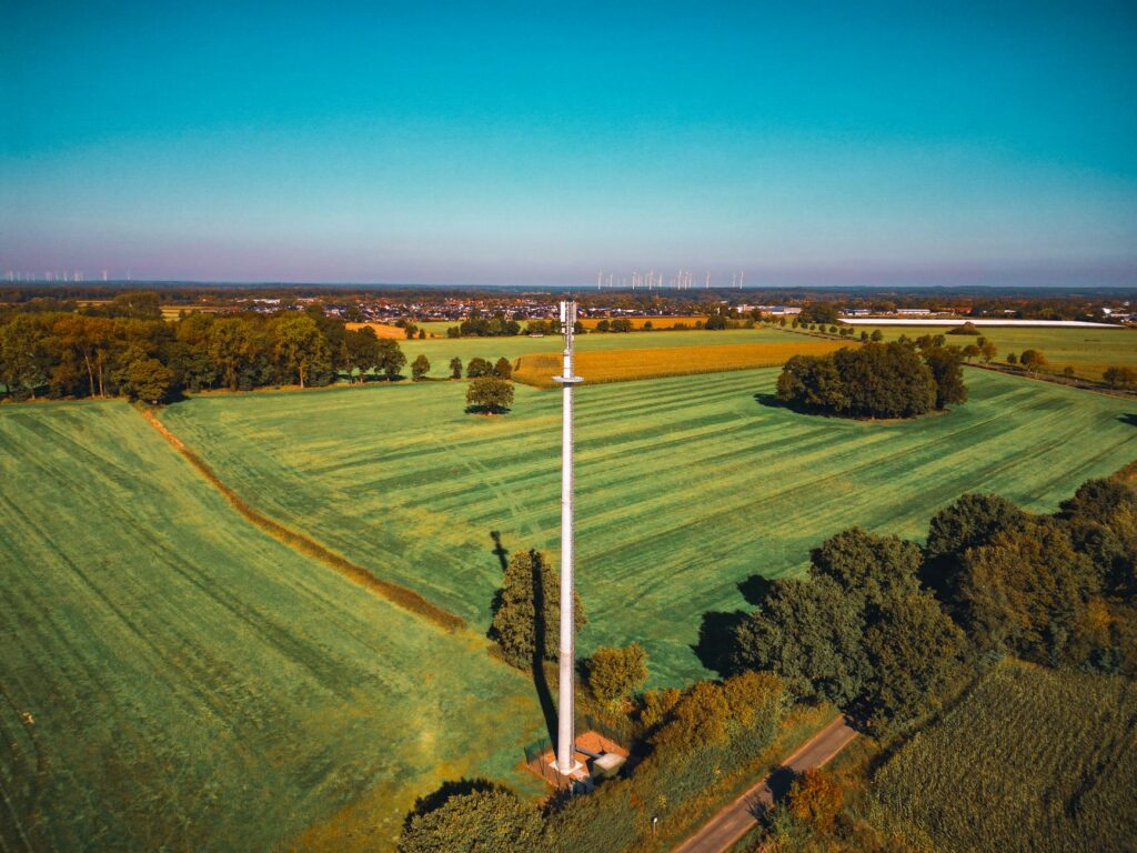
Sharing a compact dToF sensor we’ve been working with for drone obstacle av…
Table of Contents
- 👉 What Is an Obstacle Sensing Robot?
- 👉 Why Reliable Obstacle Sensing Matters in Industrial Robots
- 👉 How Obstacle Detection and Avoidance Work
- 👉 Main Sensor Types for Obstacle Sensing Robots
- 👉 LiDAR vs Depth Vision vs Ultrasonic vs Infrared
- 👉 Why dToF LiDAR Is Becoming Popular for Compact Robots
- 👉 Obstacle Sensing, SLAM, and Autonomous Navigation
- 👉 How to Choose the Right Obstacle Sensing Sensor
- 👉 Product Showcase: DTOF Solid State LiDAR HM-LD1
- 👉 Integration Tips for ROS, Embedded Platforms, and UAVs
- 👉 Industrial Applications of Obstacle Sensing Robots
- 👉 Common Mistakes When Designing Obstacle Avoidance Systems
- 👉 FAQ: Obstacle Sensing Robot Technology
- 👉 Talk to a Robotics Perception Specialist
What Is an Obstacle Sensing Robot?
An obstacle sensing robot is an autonomous or semi-autonomous machine that uses sensors, computing, and control algorithms to detect objects around it and respond before a collision happens. At the most basic level, this could be a small educational robot that stops when an ultrasonic module sees a wall. In an industrial system, though, obstacle sensing is not one little distance value. It is a full robot obstacle detection system that ties together perception, filtering, localization, mapping, risk evaluation, path planning, and motion control.
The difference between obstacle detection and obstacle avoidance is worth spelling out. Detection tells the robot that an object exists at a certain distance or inside a certain zone. Avoidance means the robot understands whether that object blocks the route, whether it is static or moving, whether the robot has enough braking distance, and what motion command is safe. A warehouse robot should not just stop forever when a pallet appears in its route. It should detect the pallet, update its local map, slow down or stop if needed, and then navigate around it if the mission allows.
Obstacle sensing robots include AMRs, AGVs, delivery robots, cleaning robots, UAVs and drones, inspection robots, security patrol robots, agricultural robots, research platforms, and educational robots. Each category has different requirements. A compact indoor robot may need short-range depth sensing and smooth people avoidance. An inspection drone may need lightweight ranging for altitude hold, terrain following, and obstacle detection near structures. A factory AMR may need robust LiDAR obstacle detection, safety-rated sensing, accurate localization, and continuous SLAM map updates.
Core perception outputs may include distance measurement, a depth image, a 3D point cloud, object presence detection, free-space estimation, collision risk scoring, and navigation map updates. These outputs are used by a controller or navigation stack to decide whether to continue, slow down, stop, reroute, or trigger a safety event. Teams building more advanced positioning and navigation stacks may also benefit from this related guide: How to Choose Visual RTK Navigation Module.
Why Reliable Obstacle Sensing Matters in Industrial Robots
Safety and Collision Prevention
Reliable obstacle sensing protects people, goods, robot frames, payloads, dock stations, doors, racks, conveyors, and production uptime. Industrial environments are never as clean as the sales demo. A warehouse aisle may look clear one second and be blocked by a forklift, pallet jack, worker, tote, cable, or temporary storage rack the next. A robot that cannot detect these changes consistently becomes a liability.
Safety is tied directly to the robot’s physical behavior. A fast AMR carrying a heavy payload needs more detection distance and more reliable perception than a slow tabletop robot. A drone flying near bridges, expressways, dams, tanks, or industrial equipment must detect obstacles early enough to hold stable flight and avoid contact. For service and delivery robots operating around people, obstacle sensing must support smooth, predictable behavior—not just panic stops.
Uptime and Operational Efficiency
Obstacle sensing directly affects uptime. False positives cause unnecessary stops, slow missions, and force operators to intervene. False negatives can lead to collisions, damaged goods, safety incidents, and downtime. Poor sensing also hurts fleet reliability because each robot may behave differently depending on lighting, floor finish, reflectivity, payload setup, or traffic conditions.
Commercial buyers should evaluate obstacle sensing as part of total system performance, not as an isolated component. A sensor with excellent range but narrow field of view may still miss side hazards. A camera-based system may work nicely in a lab but struggle in low texture, low light, or glare. A low-cost sensor may reduce the bill of materials but increase engineering cost if the software team has to build heavy filtering, calibration, and exception handling around it.
Commercial Robot Requirements vs Prototype Requirements
| Prototype Robot | Industrial Robot |
|---|---|
| Simple stop-and-turn logic | Path planning and dynamic obstacle avoidance |
| Ultrasonic or IR only | LiDAR, depth vision, SLAM, and sensor fusion |
| Controlled indoor test area | Variable lighting, reflective surfaces, dust, people, and moving vehicles |
| Short runtime expectations | Long-term reliability, maintainability, stable supply, and serviceability |
Industrial perception ecosystems include GNSS, inertial, LiDAR, and positioning suppliers such as u-blox and LiDAR technology providers such as RoboSense. These companies show where the market has gone: reliable autonomy depends on high-quality sensing, positioning, and software integration rather than one isolated component.
How Obstacle Detection and Avoidance Work
Step 1 — Sensor Data Acquisition
The obstacle avoidance pipeline starts with sensor data acquisition. Different sensors capture different physical signals. Ultrasonic sensors estimate distance from acoustic echo timing. Infrared sensors use reflected light intensity or triangulation. Stereo cameras infer depth from image disparity. Structured light sensors project a known pattern and analyze deformation. Time-of-Flight sensors estimate distance from light travel time. 2D LiDAR provides planar scan data, while 3D LiDAR and depth modules generate point clouds or depth images.
Raw data must be time-stamped, synchronized, filtered, and transformed into the robot coordinate frame. In real robots, timing matters. A sensor reading that arrives late can represent where an obstacle was, not where it is now. If the robot is moving, sensor data must line up with odometry, IMU, and control-loop timing. That is why integration quality often matters just as much as sensor hardware quality.
Step 2 — Distance and Geometry Estimation
After acquisition, the system estimates distance and geometry. A simple sensor may output one range value. A depth camera may output a depth map where each pixel contains distance. A 3D LiDAR may output a point cloud with X, Y, and Z coordinates. The navigation stack can convert these measurements into occupancy grids, voxel maps, local costmaps, object boundaries, and free-space estimates.
For dToF sensors, each measurement estimates distance by calculating the time light takes to travel from the emitter to an object and return to the receiver. Since light travels extremely fast, the electronics and signal processing need to be precise. The practical benefit is that dToF can provide active distance measurement in a compact module, supporting real-time depth perception for small robots, embedded platforms, and UAVs.
Step 3 — Obstacle Classification and Risk Assessment
Advanced robots do more than detect geometry. They classify risk. AI obstacle detection may identify people, vehicles, pallets, doors, shelves, boxes, animals, or unknown objects. Semantic segmentation can label ground, walls, free space, and obstacles. Motion tracking can distinguish static structures from moving people or forklifts. The robot can then adjust behavior based on object type and predicted motion.
AI is not a replacement for reliable depth data. A camera model may classify an object, but the navigation system still needs distance, speed, and safe clearance. A strong autonomous robot perception system combines depth sensing, filtering, AI classification, SLAM, and motion planning. Risk zones should account for robot speed, braking distance, payload, floor traction, turning radius, and safety policy.
Step 4 — Path Planning and Motion Control
Once obstacles are detected and assessed, the robot chooses a motion response. It may stop, slow down, reroute, follow a corridor, avoid a local obstacle, rebuild a map, trigger an alarm, or request human assistance. Navigation stacks often use global and local planners. The global planner determines the route from the current location to the mission target. The local planner handles near-field obstacles and converts the desired path into velocity commands.
Common planning concepts include Dynamic Window Approach, Timed Elastic Band, velocity obstacles, and model predictive control. You do not need the same planner for every robot. A small service robot, inspection crawler, AMR, and UAV may all require different control strategies. What matters is that the sensor data is accurate, timely, and compatible with the planner’s map representation.
Main Sensor Types for Obstacle Sensing Robots
Ultrasonic Sensors
Ultrasonic sensors are common in educational and hobby robotics because they are inexpensive, simple to wire, and easy to understand. They emit sound waves and measure the time required for an echo to return. For a low-speed prototype, they can support basic stop detection or wall following.
The limitations are significant for commercial systems. Ultrasonic sensors have poor angular resolution, can struggle with soft or angled surfaces, and may miss narrow objects. Scanning with a servo is slow and mechanically less robust. Multiple ultrasonic sensors can interfere with one another if not scheduled carefully. For professional obstacle sensing robots, ultrasonic sensors are better used as secondary or backup sensing rather than the primary perception layer.
Infrared Sensors
Infrared sensors are useful for short-range presence detection, cliff detection, line following, edge detection, and docking assistance. They are compact, low power, and easy to integrate with microcontrollers. Many cleaning robots and small mobile platforms use IR sensors for close-range safety functions.
IR sensing is affected by surface reflectivity and ambient light. Dark surfaces may return weak signals, while reflective surfaces may create confusing readings. Direct sunlight can reduce performance. Infrared sensors generally do not provide rich spatial geometry, so they are not sufficient as the only perception layer for industrial navigation.
2D LiDAR
2D LiDAR is widely used in AMRs and AGVs because it provides accurate planar scan data. A horizontally mounted 2D LiDAR can support mapping, localization, and front obstacle detection. Many SLAM systems were built around 2D LiDAR because the data is compact, geometrically useful, and relatively easy to process.
The main limitation is scan plane coverage. A 2D LiDAR may miss obstacles above or below its measurement plane. Forklift forks, hanging cables, table edges, low blocks, ramps, and overhanging shelves can fall outside the scan height. For this reason, many robots combine 2D LiDAR with depth cameras, 3D LiDAR, bump sensors, cliff sensors, or additional side sensors.
3D LiDAR and Solid-State LiDAR
3D LiDAR provides richer spatial geometry than a single-plane scanner. It captures height, shape, and depth distribution, making it useful for obstacle avoidance, inspection, mapping, terrain following, robotic vision development, and SLAM support. Solid-state LiDAR designs reduce or remove rotating mechanical assemblies, which can simplify integration and improve suitability for compact robots and drones.
Compact dToF LiDAR modules are especially attractive where size, weight, and power matter. Instead of relying on a single range value, these modules can deliver depth images and point cloud data. That makes them useful as a robot obstacle avoidance sensor when the system needs to understand whether an object is low, high, wide, narrow, near, or far.
Stereo Depth Cameras
Stereo depth cameras use two camera viewpoints to estimate depth from image disparity. They are valuable when the robot needs both depth and visual context. For example, a robot may need to identify boxes, people, doors, shelves, signs, or manipulation targets while also estimating distance.
Stereo systems can struggle in low-texture scenes, repetitive patterns, low light, and glare. They also require more image processing than simple range sensors. They remain powerful tools for robotics development, AI perception, manipulation, and indoor navigation when environmental conditions are appropriate.
Structured Light and ToF Depth Cameras
Structured light and ToF depth cameras are active sensing systems. Structured light projects a known pattern and measures how it deforms on surfaces. ToF depth cameras estimate distance using light travel timing or phase-based methods. These sensors can provide per-pixel distance measurement, which is useful for presence detection, manipulation, navigation, people detection, volume measurement, and obstacle sensing.
Performance depends on the sensor design and environment. Some active depth sensors perform very well indoors but lose range outdoors in bright sunlight. Engineers should compare indoor range, outdoor range, operating temperature, interface options, power consumption, and software support before selecting a module.
Sensor Fusion Systems
Sensor fusion combines multiple sensing sources such as LiDAR, IMU, cameras, GNSS/RTK, wheel odometry, depth sensors, and inertial modules. Fusion is more robust than any single sensor because each sensing modality has strengths and weaknesses. A camera may classify objects, LiDAR may provide accurate geometry, IMU may stabilize motion estimates, and wheel odometry may support short-term localization.
For embedded development, teams often need a compute platform that can handle sensor input, filtering, and navigation logic. If your team is prototyping perception pipelines, you may consider development hardware such as the RISC-V Dev Board HM-RV3 as part of the broader embedded robotics architecture.
LiDAR vs Depth Vision vs Ultrasonic vs Infrared
Choosing the right sensor for an obstacle sensing robot requires matching sensing physics to the mission. There is no universal best sensor. A slow educational robot may work with ultrasonic sensing. A warehouse AMR may require 2D LiDAR plus 3D depth coverage. A UAV may prioritize weight, power, and outdoor ranging. A service robot may benefit from depth vision and AI people detection.
| Sensor Type | Best For | Strengths | Limitations | Typical Use in Obstacle Sensing Robots |
|---|---|---|---|---|
| Ultrasonic | Low-cost short-range detection | Simple, inexpensive, easy to prototype | Low resolution, slow scanning, weak small-object detection | Basic stop detection, educational robots, backup sensing |
| Infrared | Very short-range detection | Compact, low power, simple integration | Affected by reflectivity and ambient light | Cliff detection, edge detection, close-range presence sensing |
| 2D LiDAR | Planar mapping and navigation | Accurate scan data, strong for SLAM | May miss obstacles outside scan plane | AMR localization, mapping, front obstacle detection |
| 3D LiDAR / dToF LiDAR | Depth perception and 3D obstacle detection | Point cloud output, real-time distance data, compact options | Resolution and range vary by module | Robot avoidance, drones, terrain following, inspection |
| Depth Camera | 3D vision and object-aware perception | Depth image plus visual context | Performance depends on lighting and scene texture | AI perception, manipulation, indoor navigation |
When to Use LiDAR
Use LiDAR when distance reliability, mapping, and geometry are more important than visual texture. LiDAR obstacle detection is valuable when the robot must detect surfaces and free space consistently. For AMRs, AGVs, inspection platforms, and outdoor robots, LiDAR can provide repeatable range data that is well suited to costmaps, SLAM, and collision avoidance.
When to Use Depth Vision
Use depth vision when the robot needs spatial depth plus object recognition. A robot that must detect people, boxes, doors, shelves, packages, or manipulation targets may benefit from a depth sensor combined with RGB vision or AI perception. Depth vision is especially useful for service robots, research platforms, and indoor autonomous systems that need semantic understanding.
When Ultrasonic or Infrared Is Still Useful
Ultrasonic and infrared sensors still have a place in robot design. They can be useful as secondary sensing for bump protection, dock detection, cliff detection, edge detection, and emergency backup. The key is not to expect them to provide the same spatial understanding as LiDAR or depth vision. In industrial robots, they are usually part of a layered safety and perception strategy.
Why dToF LiDAR Is Becoming Popular for Compact Robots
What dToF Means
dToF means direct Time-of-Flight. The sensor emits light pulses and directly measures how long the reflected light takes to return. Since the speed of light is known, distance can be calculated from the measured time interval. This approach makes dToF LiDAR modules attractive for compact robots that need active distance sensing without relying on scene texture.
SPAD-Based Sensing
SPAD stands for Single-Photon Avalanche Diode. At a high level, SPAD-based receivers are sensitive to very small amounts of returning light, which helps compact depth modules detect reflected signals. SPAD dToF technology can support real-time depth imaging and short-to-medium-range perception in a small form factor. For robot designers, the practical value is a compact sensor that can output distance information across a field of view rather than only one point.
Why Solid-State Matters
Solid-state LiDAR avoids rotating mechanical assemblies. Benefits can include smaller size, lower weight, easier integration, reduced mechanical wear, and better suitability for drones and compact robots. In applications where vibration, packaging space, weight, and power consumption matter, a solid-state dToF module can be easier to mount and protect than a larger mechanical scanning system.
Ideal Use Cases for Compact dToF LiDAR
Compact dToF LiDAR is suitable for front obstacle detection on small AMRs, UAV altitude hold, terrain following, smart inspection, security zone monitoring, human presence detection, robotic vision development, and SLAM support in compact systems. It is also useful where a robot needs a depth-aware view of the environment but cannot carry a large sensor or high-power compute system.
Obstacle Sensing, SLAM, and Autonomous Navigation
What SLAM Adds to Obstacle Sensing
SLAM stands for Simultaneous Localization and Mapping. It enables the robot to build or update a map while estimating its own position. Obstacle sensing provides real-time environmental input; SLAM turns that input into spatial understanding. Without localization and mapping, a robot may detect obstacles but still fail to navigate efficiently from one place to another.
Local Obstacle Avoidance vs Global Navigation
Global navigation determines the route from point A to point B. Local obstacle avoidance handles the immediate environment around the robot. A costmap represents occupied or risky space, and sensor data updates this costmap continuously. If a person steps into the path, the local planner may slow down or stop while the global plan remains unchanged. If an aisle is blocked by a pallet, the robot may update the map and request a new route.
Why 3D Data Improves Navigation
2D data can miss overhanging shelves, table edges, forklift forks, hanging cables, low obstacles below scan height, and sloped or uneven terrain. 3D depth data helps robots understand height, shape, and free space. A depth sensor for robot navigation can identify whether an obstacle is on the floor, at bumper height, above the robot, or within a safe clearance zone.
Multi-Sensor Navigation Stack
A practical navigation stack may combine a dToF LiDAR or depth camera for obstacle sensing, an IMU for motion estimation, wheel odometry for dead reckoning, visual odometry or RTK for localization, a SLAM algorithm for mapping, and a navigation planner for motion. For robots that require high-precision outdoor positioning, see How to Choose Visual RTK Navigation Module.
How to Choose the Right Obstacle Sensing Sensor
1. Ranging Distance
Start with the robot’s maximum speed and stopping distance. A sensor must detect obstacles far enough ahead for the robot to process data, make a decision, and brake safely. Indoor service robots may need shorter ranges, while outdoor robots and drones may need longer detection margins. Also consider minimum range. Some sensors have a near-field blind zone, which can matter for docking, close maneuvering, and low-speed inspection.
2. Accuracy and Repeatability
Accuracy affects clearance margins, docking, shelf alignment, aisle navigation, manipulation, and obstacle boundary estimation. Repeatability matters because a robot should not make different decisions when encountering the same object under similar conditions. Centimeter-level accuracy can be valuable for compact robots operating near walls, equipment, people, or narrow corridors.
3. Field of View
Horizontal FOV determines how much area the robot sees left to right. Vertical FOV determines whether it can detect floor obstacles, ramps, overhangs, or height variation. A wider FOV reduces blind zones, but the robot may still need multiple sensors for 360-degree coverage. Engineers should design field of view around robot geometry, turning behavior, reverse motion, and braking distance.
4. Resolution and Frame Rate
Resolution affects how much shape detail the robot can perceive. Low resolution may be enough for presence detection, while higher resolution supports shape recognition, edge detection, and segmentation. Frame rate affects response time. A sensor operating at 10 fps provides new data every 100 milliseconds, which may be acceptable for many compact robots but must be evaluated against robot speed, compute latency, and planner update rate.
5. Environmental Adaptability
Robots may operate in sunlight, nighttime, indoor lighting, reflective surfaces, dark surfaces, dust, rain, and temperature variation. Outdoor sunlight can reduce the range of active optical sensors. Reflective metal, glass, black objects, and angled surfaces may create edge cases. Always evaluate the sensor in the actual operating environment, not only in a controlled lab.
6. Interface and Software Support
Interface options affect integration time. UART can be useful for embedded controllers and flight controllers. UVC can simplify connection to PC-class systems. UDP can be useful where network-style data transport is preferred. SDK availability for Windows, Linux, and ARM Linux can reduce driver work and help teams move from prototype to deployment.
7. Power, Size, and Weight
Power, size, and weight are especially important for UAVs, small AMRs, battery-powered robots, wearable robotics, and compact inspection platforms. A sensor that consumes less power extends battery life and reduces thermal constraints. A lighter module is easier to mount on a drone or small mobile robot without affecting balance or flight time.
8. Total System Cost
The lowest-cost sensor is not always the lowest-cost system choice. A cheap sensor may require more filtering, more calibration, more mechanical protection, more redundancy, or more manual intervention. Procurement teams should consider integration labor, support burden, reliability, long-term supply, software compatibility, and performance in real environments.
Product Showcase: DTOF Solid State LiDAR HM-LD1
The DTOF Solid State LiDAR HM-LD1 is a compact 3D sensing module designed for obstacle avoidance, distance detection, autonomous navigation, UAV sensing, smart inspection, and robotic vision development. Based on SPAD dToF technology, it outputs real-time depth images and 3D point cloud data, making it suitable for engineers who need more spatial information than simple ultrasonic or infrared sensors can provide.
The HM-LD1 is designed for compact robotic systems where space, weight, and power consumption matter. At 28 g and 1.2 W, it can be integrated into small AMRs, UAVs, embedded prototypes, and robotic vision platforms. Its 60° horizontal × 45° vertical FOV gives the robot a depth-aware view of the scene rather than a single distance point, while its 40 × 30 depth resolution and 10 fps frame rate provide real-time spatial updates for obstacle detection and navigation logic.
View Product Details & Pricing ➔
Download DTOF SSL HM-LD1 Product Brochure

| DTOF Solid State LiDAR HM-LD1 Specifications | |
|---|---|
| Product Name | DTOF Solid State LiDAR HM-LD1 |
| Technology | SPAD dToF solid-state LiDAR |
| Dimension | 43.5 mm × 30 mm × 26.5 mm |
| Ranging Capability | Indoor: 0.5–25 m; Outdoor: 0.2–8 m |
| Ranging Accuracy | ±3 cm |
| Field of View | 60° horizontal × 45° vertical |
| Resolution | 40 × 30 |
| Frame Rate | 10 fps |
| Interface | UART / UDP / UVC |
| Operating Temperature | -20 ℃ to 60 ℃ |
| Power Consumption | 1.2 W |
| Weight | 28 g |
| Supported Development Platforms | SDKs for x86 Windows, x86 Linux, and ARM Linux |
| Typical Applications | Obstacle avoidance, distance detection, autonomous navigation, SLAM support, UAV altitude hold, terrain following, smart inspection, robotic vision development, zone intrusion monitoring |
Point Cloud and Depth Map Output
The HM-LD1 can provide ranging measurement data displayed as point cloud and depth data. For an obstacle sensing robot, this is valuable because the navigation algorithm can work with more than a single distance value. A depth image can support fast forward obstacle detection, while point cloud data can support geometry processing, costmap updates, SLAM experiments, and robotic vision development.
Long Measurement Range
The module’s ranging measurement is designed to be highly accurate, with real details specifying indoor ranging from 0.5 m to 25 m and outdoor ranging from 0.2 m to 8 m. The product description also notes usefulness for measuring distances to objects that are difficult for people to approach, such as bridges, expressways, and dams. This makes it relevant not only for mobile robots but also for smart inspection systems and distance measurement applications.
Compact and Lightweight Design
With a listed size of 43.5 mm × 30 mm × 26.5 mm and a weight of 28 g, the HM-LD1 is well suited for devices with limited space for depth sensors. This includes autonomous mobile robots, compact research robots, UAVs, and embedded inspection platforms. Low weight is particularly important for drones because every gram can influence payload capacity, endurance, and flight distance.
Advanced 3D Sensing with Robust Environmental Adaptability
HM-LD1 is a solid-state LiDAR module based on SPAD dToF technology, delivering real-time depth images and 3D point cloud data for accurate environmental perception. It supports obstacle avoidance, distance detection, autonomous navigation, smart inspection, and robotic vision development. With UVC, UDP, and UART interfaces, it can be integrated with PCs, Raspberry Pi-class platforms, flight controllers, and embedded systems for both prototyping and deployment.
Multi-Scenario dToF LiDAR Applications
This dToF LiDAR module supports applications for drones, robots, cameras, and security systems. It can enable UAV altitude hold and terrain following, assist robot navigation and obstacle avoidance, support SLAM, and contribute to autofocus, user presence detection, object recognition, volume measurement, and zone intrusion monitoring. Its SDK support for x86 Windows, x86 Linux, and ARM Linux helps engineering teams integrate the module across multiple development environments.
Integration Tips for ROS, Embedded Platforms, and UAVs
ROS and Robotics Middleware
In ROS or ROS 2 systems, depth data can be published as depth images, point clouds, range messages, or custom sensor messages. Engineers should define coordinate frames carefully, publish accurate time stamps, and verify transforms between the sensor, robot base, IMU, camera frame, and map frame. Visualization in RViz helps validate whether the point cloud appears in the correct position and whether obstacles align with the real environment.
For navigation, sensor data is often converted into local costmaps. The costmap marks occupied or risky zones and gives the local planner a representation of nearby hazards. Filtering may remove ground points, noise, invalid measurements, or objects outside the robot’s relevant height range. Engineers should tune obstacle inflation radius, persistence time, minimum and maximum range, and clearing behavior to match robot dynamics.
Embedded Linux Integration
Embedded Linux integration requires attention to CPU load, memory usage, data transport, driver stability, watchdog handling, and power budgeting. ARM Linux support is especially useful for compact robots because many edge compute platforms use ARM processors. UART may be preferred for simpler embedded communication, while UVC or UDP may be easier for higher-level depth or point cloud streaming depending on the software stack.
If your team is prototyping embedded perception pipelines, consider pairing sensing modules with a development platform such as the RISC-V Dev Board HM-RV3. The key is to validate sensor drivers, data latency, compute load, and recovery behavior before moving to field deployment.
UAV Integration
UAV integration places strict limits on weight, power consumption, vibration resistance, and mounting position. A depth sensor may support altitude hold, terrain following, landing assistance, forward obstacle detection, and distance measurement near structures. Engineers must also account for sunlight exposure, propeller vibration, airframe flex, cable strain, and sensor field of view relative to flight direction.
For drones, sensor placement is especially important. A forward-facing sensor may help avoid walls or structures, while a downward-facing sensor may support altitude hold and landing. Terrain following requires not only range data but also filtering and control tuning so that the aircraft responds smoothly rather than reacting abruptly to noisy measurements.
Calibration and Mounting
Mechanical integration can determine whether a good sensor performs well in the robot. Mounting height, tilt angle, vibration isolation, cable routing, enclosure design, lens cleanliness, and coordinate alignment all matter. A sensor mounted too low may be blocked by the robot chassis. A sensor tilted incorrectly may miss low obstacles or overemphasize the floor. A dirty window may degrade optical performance.
Engineers should define the sensor-to-robot transform accurately and verify it through testing. In ROS, this typically means publishing the correct static transform and checking the data in visualization tools. During field tests, include edge cases such as black objects, reflective surfaces, angled objects, glass, moving people, low obstacles, and bright sunlight.
Industrial Applications of Obstacle Sensing Robots
Warehouse AMRs and AGVs
Warehouse AMRs and AGVs operate around pallets, workers, forklifts, racks, conveyor stations, and temporary obstructions. Obstacle sensing supports safe navigation, dynamic rerouting, docking, aisle driving, and fleet productivity. Depth data is especially useful when the robot must detect hazards at different heights, such as pallet overhangs, forklift forks, and objects protruding into the aisle.
Inspection Robots
Inspection robots may work near bridges, dams, tunnels, pipelines, industrial plants, utility structures, and other environments that are difficult or unsafe for people to approach. Depth sensing helps these robots maintain distance from surfaces, detect structural features, avoid collisions, and measure object distance. Compact dToF LiDAR can be useful when the platform is small and power constrained.
UAVs and Drones
Drones use obstacle sensing for terrain following, altitude hold, landing support, forward obstacle detection, and distance measurement. In inspection and mapping missions, a UAV may need to fly near walls, towers, bridges, roofs, or industrial equipment. A lightweight depth module can support situational awareness without adding excessive payload mass.
Service and Delivery Robots
Service and delivery robots operate around people, furniture, doors, curbs, bags, pets, and unpredictable obstacles. Smooth avoidance is important because users expect the robot to behave naturally. Depth sensors help detect legs, furniture edges, open doors, floor objects, and obstacles that may not be captured reliably by a single planar scan.
Security and Zone Monitoring
Depth sensors can support user presence detection, zone intrusion monitoring, object recognition, and distance-aware security functions. Compared with basic motion detection, depth sensing can provide position and distance context. This helps systems distinguish whether an object is inside a protected zone and how it is moving through the monitored area.
Common Mistakes When Designing Obstacle Avoidance Systems
Mistake 1 — Choosing a Sensor Only by Price
Low-cost sensors can increase engineering cost if they require complex filtering or fail in real environments. The true cost of a robot obstacle avoidance sensor includes integration, software development, field failures, maintenance, and support. A slightly higher-performance sensor may reduce total cost by improving reliability and shortening development time.
Mistake 2 — Ignoring Field of View
A high-accuracy sensor with a narrow FOV may still miss obstacles outside its detection cone. Engineers should map blind zones around the robot and consider forward, side, rear, low, and high obstacles. Multiple sensors may be required if the robot turns, reverses, docks, or operates around people.
Mistake 3 — Assuming Indoor Performance Equals Outdoor Performance
Sunlight, reflectivity, and outdoor operating conditions can change optical sensor behavior significantly. Active optical sensors often have different indoor and outdoor ranges. Outdoor testing should include bright sunlight, dark objects, reflective metal, angled surfaces, and long detection distances.
Mistake 4 — Treating AI as a Replacement for Good Depth Data
AI models are only as reliable as the sensor data and training context behind them. A camera model may detect a person, but the navigation stack still needs accurate distance, localization, and motion planning. Good obstacle avoidance depends on reliable depth data, sensor fusion, costmaps, and control logic.
Mistake 5 — Not Testing Edge Cases
Edge cases often determine field reliability. Test black objects, reflective metal, glass, angled surfaces, small obstacles, moving people, low obstacles, overhanging obstacles, bright sunlight, low light, dusty environments, vibration, and dirty sensor covers. A robot that only works in a clean laboratory is not ready for industrial deployment.
Mistake 6 — Poor Mechanical Mounting
Vibration, tilt, occlusion, and dirty covers can reduce performance even when the sensor itself is good. Mechanical design should protect the sensor while preserving field of view and optical clarity. Cable routing should prevent strain, and mounting should maintain calibration over time.
FAQ: Obstacle Sensing Robot Technology
What is the best sensor for an obstacle sensing robot: ultrasonic, infrared, camera, or LiDAR?
How does AI obstacle detection in robots actually work?
How can I add 360-degree obstacle scanning to a robot?
Can an obstacle sensing robot work outdoors?
Is LiDAR enough for autonomous navigation?
What field of view does an obstacle sensing robot need?
How important is frame rate for obstacle avoidance?
What is the difference between a depth map and a point cloud?
Why do some sensors have different indoor and outdoor ranges?
Can I use one front-facing sensor for full obstacle avoidance?
What specifications matter most when sourcing an obstacle sensing module?
Talk to a Robotics Perception Specialist
Choosing the right obstacle sensing robot architecture depends on your robot’s speed, size, operating environment, navigation stack, and safety requirements. If you are developing an AMR, UAV, inspection robot, service robot, or embedded perception system, our team can help you evaluate dToF LiDAR, depth sensing, SLAM integration, and platform compatibility.
Contact Us for Obstacle Sensing Robot Solutions
📚 References & Further Reading
- Industry Standard: u-blox | RoboSense
- Related Guide: How to Choose Visual RTK Navigation Module | DTOF Solid State LiDAR HM-LD1 | RISC-V Dev Board HM-RV3 | Contact Us