


What Are LiDAR Sensors? How They Work, Key Specs, and the Right Choice for Robots
If a robot is going to avoid a pallet, hold a safe distance from a wall, navigate an aisle, or estimate its height above a landing surface, it needs dependable distance information. A camera can show the robot what is in front of it, but getting reliable depth from a camera may depend on lighting, surface texture, stereo geometry, or a fairly heavy perception algorithm. LiDAR takes a more direct approach: it sends out light, measures the return, and uses that timing or modulation information to estimate distance.
That distance data may come back as a single range, a two-dimensional scan, a depth image, or a three-dimensional point cloud. Robot software can then use it for obstacle avoidance, mapping, localization, inspection, altitude control, presence detection, and automation. Here’s the deal: LiDAR is not a magic window into the environment. It is a measurement instrument, and every measurement instrument has operating limits.
Asking “what are LiDAR sensors?” is only the starting point. The useful engineering questions are more specific. What is the smallest object the system must detect? How much sunlight will hit the sensor? What happens when the target is black, glossy, transparent, wet, or sharply angled? How much time does the robot have to stop? What interface, power budget, field of view, and mechanical envelope does the design allow?
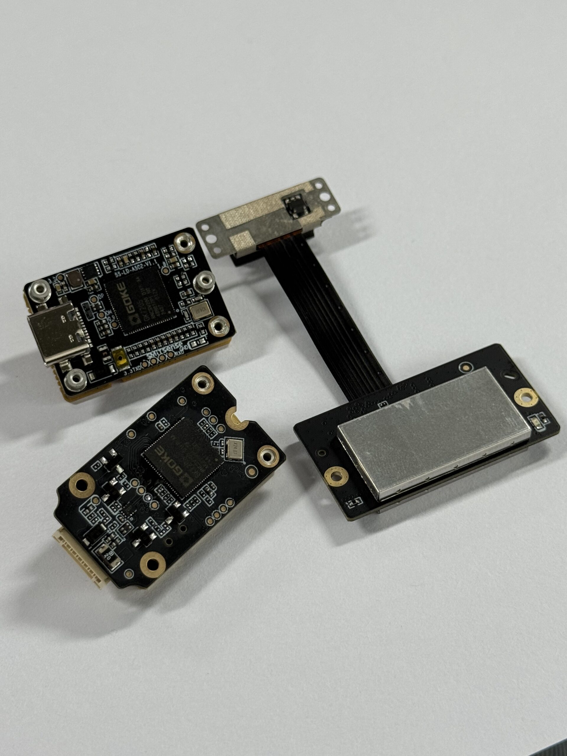
This guide covers the operating principle, major LiDAR architectures, data formats, specifications, environmental limits, integration concerns, and selection process. It also uses the compact HM-LD1 solid-state dToF LiDAR as a practical example of how a real product should be evaluated before it is installed on a robot or drone.
Short answer: A LiDAR sensor is an active optical sensing device that emits laser or infrared light, detects reflections from surrounding surfaces, and uses the returned signal to estimate distance. Depending on its architecture, it may output a single distance, a two-dimensional scan, a depth image, or a three-dimensional point cloud.
Table of Contents
- 👉 What Is a LiDAR Sensor?
- 👉 How Do LiDAR Sensors Work?
- 👉 Major Types of LiDAR Sensors
- 👉 What Data Does a LiDAR Produce?
- 👉 Key LiDAR Specifications
- 👉 Environmental Factors and Measurement Limits
- 👉 LiDAR vs. Other Sensors
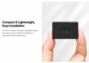
- 👉 Robot and Drone Applications
- 👉 Hardware and Software Integration
- 👉 HM-LD1 Product Specifications
- 👉 How to Choose a LiDAR Sensor
- 👉 Prototype and Validation Checklist
- 👉 Limitations and Common Mistakes
- 👉 Conclusion
- 👉 Frequently Asked Question
What Is a LiDAR Sensor?
A LiDAR sensor uses emitted light and measured reflections to determine the distance between the sensor and surrounding surfaces. LiDAR is commonly expanded as Light Detection and Ranging. It is an active sensing technology because it supplies its own optical illumination instead of depending entirely on ambient light.
LiDAR meaning and basic operation
A typical measurement starts when an emitter sends a pulse or modulated optical signal toward the scene. Some of that energy reaches an object and reflects back toward the receiver. The receiver optics and photodetector collect the return, and onboard electronics estimate how far the light traveled. That range is then associated with a direction, calibrated optical ray, or detector pixel.
One measurement tells the system very little by itself. Repeating the process over many directions or across an array creates useful spatial information. A mobile robot can use those measurements to identify open floor space, estimate wall locations, build a local map, or trigger a stop command when an obstacle enters a defined zone.
What a LiDAR sensor measures
LiDAR primarily measures geometry. It can indicate that a surface exists at a particular distance and direction, but it does not automatically know whether that surface is a person, pallet, vehicle, wall, branch, or dock edge. Identification normally requires perception software, machine-learning models, rule-based segmentation, or sensor fusion with cameras and other devices.
LiDAR, rangefinders, and depth sensors
A laser rangefinder may report one distance along one direction. A two-dimensional scanning LiDAR measures a series of ranges across a plane. A three-dimensional LiDAR distributes measurements through a volume, while an array-based depth sensor produces an image-like grid in which each pixel represents range. The terminology overlaps, so look past the marketing label and verify the actual optical architecture and data output.
How Do LiDAR Sensors Work?
1. The emitter transmits light
The process begins with a laser, VCSEL, or other controlled optical emitter. Near-infrared wavelengths are common because they are invisible to users and can be paired with suitable detectors and optical filters. Different products use different wavelengths, pulse energies, modulation schemes, illumination patterns, and optical powers.
2. Light reflects from the target
The target has a major effect on the return. A matte, diffusely reflecting surface sends light in many directions and often provides a stable signal. Glass, mirrors, water, polished metal, dark coatings, and steeply angled surfaces can transmit, absorb, or redirect much of the emitted energy. An object can therefore be inside the stated range and still produce weak or invalid data.
3. The receiver detects the return
Receiver optics collect returning photons and direct them to a photodetector. SPAD devices, photodiodes, optical filters, amplification, and embedded signal processing may be used to separate the intended return from ambient optical noise. Bright sunlight matters because it adds background photons and can reduce the signal-to-noise ratio, especially for distant or dark targets.
4. Travel time is converted into distance
Distance = (speed of light × round-trip travel time) ÷ 2
The division by two matters because the measured interval includes the trip from the sensor to the target and the return trip from the target to the receiver. Direct time-of-flight, or dToF, systems estimate the timing of returned pulses or photons. Indirect time-of-flight systems infer range from the phase difference of modulated light. FMCW LiDAR uses coherent frequency-modulated methods and can potentially measure range and relative velocity. Triangulation sensors use geometric displacement and are generally intended for shorter-range measurements.
5. Measurements become spatial data
Each range must be assigned to a calibrated direction or pixel. Sensor firmware or host software can then transform that measurement into X, Y, and Z coordinates relative to the sensor. For robotic work, those coordinates must be transformed again into the robot base, camera, inertial, vehicle, or map frame. In the shop, this is where many otherwise good prototypes start showing errors: the sensor works, but the coordinate frame is wrong.
Suggested visual: direct time-of-flight ranging principle showing emitted light, a target reflection, and return detection.
Major Types of LiDAR Sensors
Single-point LiDAR
A single-point sensor measures one direction or a small region. Common uses include altitude measurement, autofocus, tank or material-level sensing, docking, and straightforward forward proximity detection. It is compact and power-efficient, but it does not provide broad environmental coverage by itself.
Two-dimensional scanning LiDAR
A 2D scanner measures ranges across a plane, often by rotating or steering a beam. It is widely used for indoor mobile-robot localization and planar obstacle detection. Mounting height is critical. A horizontal scan can miss floor hazards, overhanging objects, table surfaces, low shelves, and obstacles above or below the scan plane.
Mechanical 3D LiDAR
Mechanical 3D systems rotate an optical assembly to obtain broad spatial coverage. They can deliver dense point clouds and wide horizontal coverage for mapping and autonomous navigation. The tradeoffs are familiar to anyone who has packaged moving hardware: size, weight, cost, sealing, vibration, mechanical wear, and connector placement all become more complicated.
MEMS and hybrid solid-state LiDAR
Some systems use small mirrors or restricted-motion beam-steering mechanisms. Vendors may call these solid-state or hybrid solid-state, so the label should be checked against the actual design. These systems can reduce the size of the scanning mechanism while retaining controlled beam movement.
Flash and array-based solid-state LiDAR
Flash or area-based sensors illuminate a region and measure returns with a detector array. They can produce depth images without a large rotating scanner, which makes them attractive for embedded vision, drones, compact robots, presence sensing, and fixed forward or downward perception.
| Architecture | Measurement principle | Potential advantages | Common considerations |
|---|---|---|---|
| dToF | Measures optical return timing | Direct range measurement and useful operating range | Ambient light, reflectivity, timing, and detector design |
| iToF | Measures phase shift in modulated light | Dense depth imaging and compact integration | Phase ambiguity, multipath effects, and outdoor conditions |
| FMCW | Uses coherent frequency-modulated measurement | Potential range and relative-velocity information | Optical and processing complexity |
| Triangulation | Uses geometric displacement | Accurate short-range profiling | Usually optimized for shorter distances |
What Data Does a LiDAR Produce?
Distance values
The simplest output is a measured range. A reliable interface should also distinguish valid measurements from saturated, low-confidence, out-of-range, or otherwise invalid values. Treating invalid data as zero distance can cause false collision alarms; treating it as unlimited free space can be much worse.
Depth maps
A depth map is an image-like matrix whose pixel values represent distance rather than visible color. A 40 × 30 depth resolution contains 1,200 potential depth samples per frame before invalid points are removed. That is measurement resolution, not camera-grade visual detail.
Point clouds
A point cloud expresses measurements as X, Y, and Z coordinates. Organized point clouds retain the original depth-image arrangement, while unorganized point clouds are stored as lists of points. Timestamps and coordinate frames are essential when either the robot or the sensor is moving.
Confidence and signal information
Depending on the product and protocol, the sensor may also provide confidence, amplitude, signal strength, status, or validity fields. These values help application software reject weak returns and identify operating problems. Confirm the exact fields in the current interface documentation rather than assuming that every depth module reports the same information.
From measurement to robot action
Raw LiDAR data usually needs filtering, time alignment, coordinate transformation, segmentation, and conversion into an obstacle layer, local map, or control input. A planner selects a path or response, and a controller commands the actuators. The LiDAR is an important perception component, but it is not the complete autonomy system.
Key LiDAR Specifications Engineers Must Compare
Minimum and maximum range
Maximum range is meaningful only when the target, reflectivity, lighting, angle, and detection threshold are stated. Indoor, nighttime, and full-daylight performance should be separated. Minimum range matters just as much because an object inside the near blind zone may not be measured reliably.
Accuracy, precision, repeatability, and resolution
Accuracy describes how close a measurement is to the true distance. Precision or repeatability describes how consistent repeated measurements are. Range resolution is the smallest distinguishable distance increment, while spatial resolution describes the number or angular density of measurement locations. These values are not interchangeable.
Horizontal and vertical field of view
Field of view determines the angular region observed by the sensor. A wide FOV covers more space, but it does not automatically increase detail. Plot the FOV from the actual mounting position and include chassis occlusion, installation tilt, minimum range, and the dimensions of critical obstacles.
Angular and spatial resolution
Object detection depends on how many measurement rays actually strike the object. A thin cable, pallet fork, branch, chair leg, or platform edge may be difficult to detect at range even when it lies inside the stated FOV. Select resolution from the smallest safety-critical or mission-critical object.
Frame rate and latency
Frame rate indicates how often measurement frames are produced, but it does not equal end-to-end latency. The total response includes optical acquisition, sensor processing, transport, buffering, host processing, planner delay, control delay, actuator response, and braking. Required detection distance must include all those delays and a safety margin.
Wavelength and emitter architecture
Wavelength affects detector selection, target response, ambient-light interaction, filtering, and laser-safety engineering. A wavelength or power-consumption number alone does not establish an eye-safety classification. Request documented safety and compliance information for the exact production configuration.
Reflectivity and ambient-light tolerance
Bright diffuse targets usually return more optical energy than dark or absorptive materials. Retroreflective surfaces can produce exceptionally strong returns, while glass and mirrors can redirect or transmit light. A lux-qualified outdoor range is more useful than an unqualified claim, but it still cannot represent every sun angle and surface condition.
Interface and bandwidth
UART is useful for straightforward embedded communication, while UDP supports networked data delivery. UVC can expose compatible depth output through video-oriented software. Verify protocol details, bandwidth, packet-loss behavior, serialization overhead, timestamps, supported operating systems, and host CPU load.
Power, thermal limits, size, and weight
Power consumption affects battery life and enclosure temperature. Weight affects UAV payload and flight endurance, while dimensions and connector clearance determine whether the device fits the mechanical design. Operating temperature does not independently prove resistance to dust, water, shock, vibration, condensation, or solar heating.
Environmental Factors and Real-World Measurement Limits
Bright sunlight
Sunlight introduces background photons that compete with the active return. Effective range can decrease as signal-to-noise ratio falls, particularly for distant, dark, small, or angled targets. Test the sensor at the actual mounting angle during the brightest expected operating conditions.
Rain, fog, dust, and airborne particles
Airborne particles can scatter emitted light, create false near returns, and attenuate the signal traveling to and from the intended object. Performance depends on particle density, wavelength, distance, processing, and filtering. General statements about outdoor operation should not replace application testing.
Glass, mirrors, black surfaces, and water
Clear glass may transmit light, reflect a partial return, or generate multiple paths. Mirrors and polished metal can direct the return away from the receiver. Black materials may absorb more energy, while water can behave differently with angle, surface condition, and wavelength. Invalid-depth handling is therefore a core software requirement.
Interference and enclosure effects
Multiple nearby active optical sensors may create cross-talk under some conditions. Protective windows can also alter performance through reflections, dirt, scratches, coatings, condensation, or incorrect spacing. Temperature changes can affect electronics, optics, mounting alignment, and calibration.
Engineering rule: A datasheet maximum range is not a guaranteed detection distance for every object. Validate representative targets at realistic angles, speeds, lighting levels, temperatures, and contamination conditions.
LiDAR vs. Cameras, Radar, and Ultrasonic Sensors
| Technology | Primary strength | Common limitation | Typical robotic role |
|---|---|---|---|
| LiDAR | Direct geometric depth | Optical surface and weather sensitivity | Mapping, obstacle detection, ranging |
| RGB camera | Color, texture, and semantic information | Lighting and metric-depth challenges | Recognition, inspection, teleoperation |
| Stereo or depth camera | Dense local depth plus imagery | Texture, sunlight, and compute constraints | Manipulation and near-field perception |
| Radar | Long-range and adverse-weather operation | Lower spatial detail in many systems | Velocity and long-range detection |
| Ultrasonic | Low-cost short-range proximity | Wide beam and limited spatial detail | Docking and near-field detection |
LiDAR is often the better primary sensor when the application depends on direct geometry, obstacle distance, local mapping, or operation in visually low-texture environments. Cameras are generally stronger when color, text, labels, or semantic classification matters. Radar is attractive for long-range velocity measurement and difficult weather, while ultrasonic sensors offer economical short-range coverage.
Most robust systems use complementary sensing rather than declaring one technology the universal winner. Optical sensing suppliers such as Domisensor illustrate the broader perception-sensor ecosystem. LiDAR can also complement GNSS, RTK, and positioning systems available from navigation technology providers such as CHC Navigation. These external links provide industry context and are not sources for the HM-LD1 specifications below.
LiDAR Applications in Robots, Drones, and Industrial Systems
Mobile-robot obstacle avoidance
LiDAR measurements can populate local obstacle zones used by a navigation planner. Successful avoidance depends on FOV coverage, minimum range, object size, stopping distance, measurement validity, and mounting position. A forward sensor may need complementary side, rear, bumper, or near-field coverage.
Localization and SLAM
Simultaneous localization and mapping uses sensor observations and motion estimates to construct a map while estimating the robot’s position within it. Results depend on environmental geometry, odometry, timestamps, calibration, algorithms, and sensor quality. LiDAR supplies local geometry; it does not eliminate the need for good motion estimation and well-managed timing.
UAV altitude hold and terrain following
A downward-facing LiDAR can estimate height above the measured surface and support altitude hold or terrain following. The design must account for minimum range, ground reflectivity, slope, vegetation, propeller vibration, landing gear, sunlight, payload weight, and flight-control latency.
Inspection and volume measurement
Depth and point-cloud data can assist inspections of warehouses, facilities, bridges, expressways, dams, and difficult-to-access structures. Volume measurement requires calibrated geometry, controlled viewpoints, sufficient resolution, overlap between frames, and management of occlusions. A compact sensor alone should not be represented as a complete certified inspection system.
Presence detection and zone monitoring
Depth data can detect occupancy, movement, or intrusion into defined three-dimensional zones. Low-resolution depth may reveal less visual detail than an RGB camera, but privacy performance depends on the complete data pipeline, retention policy, and system configuration.
Autofocus and camera assistance
Independent range measurements can support autofocus, trigger logic, subject-presence detection, or camera exposure decisions. LiDAR and cameras are often complementary: one provides geometry while the other supplies visual appearance and semantic detail.
How to Integrate a LiDAR with a Robot or Drone
1. Confirm electrical requirements
Verify supply voltage, power budget, startup behavior, connector pinout, logic levels, grounding, cable length, and protection requirements from current documentation. Do not derive electrical compatibility from an interface name alone.
2. Select the communication interface
UART provides simple embedded communication with a low pin count. UDP is useful for networked delivery and flexible host placement, but the application must manage packet loss and timing. UVC can suit software that consumes compatible video-like depth streams. Confirm the actual protocol behavior in the product documentation.
3. Choose the host platform
A PC offers development convenience, while Raspberry Pi, Jetson, and embedded Linux computers provide smaller deployment options. A flight controller or microcontroller may have tighter processor, memory, and bandwidth limits. Interface compatibility does not guarantee that every host can process the complete data stream efficiently.
4. Install the SDK or driver
Published HM-LD1 support includes x86 Windows, x86 Linux, and ARM Linux SDKs. ROS and OpenCV may serve as higher-level development layers where suitable integration support is available, but general Linux support should not be confused with a verified, maintained, prebuilt package.
5. Calibrate the coordinate frame
Measure the sensor’s translation and rotation relative to the robot base, camera, inertial unit, or flight frame. Even a few degrees of orientation error can shift projected obstacles, distort maps, and produce incorrect altitude or ground estimates.
6. Filter and validate measurements
Implement invalid-depth handling, confidence thresholds where available, temporal filters, outlier rejection, ground removal, and application-specific zones. Filtering should suppress noise without hiding fast-moving or small critical objects.
7. Measure end-to-end latency
Timestamp acquisition, host receipt, perception output, planner response, and actuator command. A 10 fps sensor has a nominal 100-millisecond frame interval, but buffering and processing can make the complete response longer.
8. Design a stable mount
The mount should resist vibration and flex while preserving optical-window clearance, thermal paths, cable strain relief, and connector access. Check that the chassis, propellers, payload, wheels, and landing gear do not obstruct the FOV.
- ⚙️ Confirm electrical compatibility before connecting the module.
- ⚙️ Preserve timestamps and document every coordinate-frame transform.
- ⚙️ Define explicit behavior for invalid, missing, or stale measurements.
- ⚙️ Measure the complete perception-to-actuation delay on the actual machine.
HM-LD1 Compact 3D dToF LiDAR: Real Product Specifications
The HM-LD1 illustrates how the preceding specifications combine in a compact solid-state depth sensor. It is described as a SPAD direct time-of-flight LiDAR that delivers real-time depth images and 3D point-cloud data for robot perception, obstacle avoidance, distance measurement, UAV altitude sensing, autonomous navigation, SLAM development, inspection, presence detection, volume measurement, zone monitoring, autofocus, and embedded vision.
| Specification | HM-LD1 value | Engineering significance |
|---|---|---|
| Sensing technology | Solid-state SPAD dToF LiDAR | Produces active depth measurements without a large rotating scanner. |
| Depth resolution | 40 × 30 | Provides 1,200 potential depth samples per frame before invalid-point filtering. |
| Indoor ranging capability | 0.5–25 m in structured tables | Medium-range indoor or nighttime perception within the published conditions. |
| Outdoor ranging capability | 0.2–8 m at 80 klux | Declares a daytime envelope under bright ambient light. |
| Ranging accuracy | Approximately ±3 cm | Supports distance and depth tasks subject to target and environmental conditions. |
| Field of view | 60° horizontal × 45° vertical | Covers a forward or downward three-dimensional region. |
| Frame rate | 10 fps | Delivers up to ten depth frames per second; system latency remains separate. |
| Wavelength and emitter | 940 nm VCSEL | Uses near-infrared active illumination for dToF ranging. |
| Interfaces | UART, UDP, UVC | Provides embedded, networked, and video-class integration options. |
| Operating temperature | −20°C to 60°C | Published operating range, not proof of complete environmental protection. |
| Power consumption | 1.2 W | Relevant to batteries, thermal design, and mobile-system runtime. |
| Weight | 28 g | Useful for payload-sensitive robot and UAV designs. |
| SDK platforms | x86 Windows, x86 Linux, ARM Linux | Supports desktop and embedded development platforms. |
Mechanical integration note: Published HM-LD1 materials contain more than one enclosure-dimension value. One structured table reports 43.5 × 30 × 26.5 mm, while another product description reports 43.5 × 43.5 × 28.5 mm. The alternative entry also places resolution under a dimensions heading without listing enclosure size.
Request the current mechanical drawing, connector location, mounting references, and clearance specification before designing a production enclosure. The narrative description also states 0–25 m for indoor or nighttime operation, whereas the structured tables state a 0.5 m indoor minimum. Use the current approved documentation for final design decisions.
The HM-LD1’s 28 g mass and 1.2 W published power consumption make it interesting for small robots, embedded equipment, and UAV payloads. Its 60° × 45° field of view is useful for a targeted forward or downward sensing zone, but it is not all-around coverage. The 40 × 30 depth output can support broad obstacle zones, altitude sensing, presence detection, and development work, although thin objects at long range may still be undersampled.
Download the DTOF SSL HM-LD1 product brochure or read the engineering comparison of HM-LD1 vs. Sony AS-DT1. Published specifications should be checked against the latest current product documentation before procurement or production release.
How to Choose the Right LiDAR Sensor for a Robot
Step 1: Define the smallest critical object
Identify whether the system must detect a human leg, pallet fork, cable, branch, landing edge, vehicle, wall, or another object. The dimensions and orientation of that target determine the spatial or angular resolution needed at the required distance.
Step 2: Calculate required detection distance
Combine robot speed, object speed, sensor delay, communication delay, processing time, control time, braking distance, and a suitable safety margin. The useful detection range under worst-case conditions must exceed this value.
Step 3: Define the environmental envelope
Separate warehouse use from operation near open doors, full sunlight, nighttime, fog, rain, dust, reflective floors, or dirty optical windows. Evaluate published ranges only under their stated conditions.
Step 4: Determine coverage
Choose horizontal and vertical FOV from mounting height, tilt, near-field blind zones, chassis obstructions, and required surrounding coverage. A fixed 60° horizontal FOV does not provide 360-degree awareness.
Step 5: Match resolution and update rate to motion
Low-resolution 3D depth can suit broad obstacle zones, presence detection, or altitude sensing, but it may not resolve thin objects at long range. Frame rate must be evaluated within the complete motion-control loop.
Step 6: Evaluate interfaces and software
Confirm protocol documentation, electrical compatibility, SDK architecture, sample code, operating-system support, update process, timestamps, error reporting, and reconnect behavior. Verify ROS or OpenCV integration instead of assuming it from general Linux support.
Step 7: Confirm power and mechanical constraints
Review battery capacity, thermal load, payload mass, mounting stiffness, optical clearance, connector access, cable routing, and enclosure protection. Request an approved mechanical drawing when published dimensions conflict.
Step 8: Review safety and compliance documents
Request applicable laser classification, EMC, environmental, regulatory, quality, and production documentation. Do not infer certification from wavelength, emitter type, or power consumption.
Step 9: Prototype with representative targets
Test black fabric, glossy metal, glass, reflective material, floor edges, angled surfaces, direct sunlight, contamination, moving objects, and communication failures. Testing should reproduce actual mounting geometry and speed.
Step 10: Evaluate supplier and lifecycle support
Confirm sample availability, supply continuity, firmware versioning, mechanical revisions, calibration procedures, customization options, technical support, and change-notification processes.
When HM-LD1 is a logical candidate: Consider it when the design requires a published 28 g compact 3D depth module, 60° × 45° FOV, 40 × 30 depth output, approximately ±3 cm accuracy, 1.2 W power consumption, and outdoor ranging up to 8 m under the stated 80 klux condition. Validate object size, speed, reflectivity, latency, and environment before selection.
- ✅ Choose from the actual detection problem, not the product headline.
- ✅ Compare minimum range, FOV, resolution, latency, and target performance together.
- ✅ Treat environmental testing as part of selection, not as an afterthought.
- ✅ Confirm mechanical drawings and software support before committing to production.
LiDAR Prototype and Validation Checklist
Optical tests
- ⚙️ Confirm minimum-range behavior and near-field blind zones.
- ⚙️ Measure useful range for representative black, white, matte, glossy, glass, and reflective targets.
- ⚙️ Vary target angle, size, partial occlusion, sunlight, and mixed indoor-outdoor lighting.
- ⚙️ Repeat testing with a dirty, scratched, or condensed protective window where applicable.
Dynamic tests
- ⚙️ Test maximum robot speed, crossing objects, and approaching objects.
- ⚙️ Measure complete acquisition-to-actuation latency and emergency stopping distance.
- ⚙️ Evaluate dropped frames, delayed packets, communication interruption, and recovery.
Mechanical and environmental tests
- ⚙️ Inspect vibration, mount flex, connector retention, cable strain, and thermal expansion.
- ⚙️ Check self-occlusion, landing gear, propellers, wheels, payloads, and chassis edges.
- ⚙️ Test the intended temperature, contamination, weather, and enclosure-window conditions.
Software and production tests
- ⚙️ Validate invalid-data handling, timestamps, coordinate transforms, startup, and reconnection.
- ⚙️ Measure CPU load, memory use, packet loss, and SDK or firmware compatibility.
- ⚙️ Evaluate unit-to-unit variation, incoming inspection, calibration, end-of-line verification, replacement, and field service.
LiDAR Limitations and Common Engineering Mistakes
Selecting by maximum range alone
Range without target reflectivity, lighting, angle, object size, and detection criteria is incomplete. Outdoor-qualified range and indoor range should never be merged into one unconditional value.
Confusing accuracy with resolution
A LiDAR may estimate the range to a measured wall accurately while lacking sufficient spatial samples to detect a thin cable. Accuracy describes measured distance, not guaranteed object detectability.
Treating frame rate as latency
Acquisition, transport, buffering, filtering, planning, control, and braking all contribute to response time. A 10 fps output does not prove that the robot reacts within 100 milliseconds.
Assuming every object returns valid data
Glass, mirrors, black fabric, water, polished metal, steep angles, fog, dust, and dirt can produce weak, redirected, scattered, or invalid measurements. Systems need explicit invalid-data behavior and complementary safeguards.
Ignoring minimum range and mounting calibration
Near-field blind zones can allow close obstacles to go unmeasured. Incorrect mounting transforms can shift obstacles, distort maps, and corrupt altitude estimates. Both issues must be addressed during mechanical design and calibration.
Using one general-purpose LiDAR as the only safety mechanism
Safety-related equipment may require redundancy, diagnostics, validated stopping functions, fail-safe behavior, and compliance with applicable machinery or robotics standards. A general perception module should not automatically be treated as a safety-rated protective device.
Choosing LiDAR by the Application, Not the Headline Range
What are LiDAR sensors in practical engineering terms? They are active optical instruments that convert reflected light into geometric distance data. Their outputs can range from a single distance to a depth map or 3D point cloud, but successful deployment depends on much more than maximum range.
The correct choice must account for minimum range, critical object size, field of view, accuracy, spatial resolution, frame rate, total latency, target reflectivity, ambient light, weather, interface support, software maturity, weight, power, temperature, mounting, and compliance requirements.
HM-LD1 is a practical candidate for compact robots, drones, embedded vision systems, and fixed depth-sensing applications that can operate within its published 40 × 30 resolution, 60° × 45° FOV, 10 fps frame rate, approximately ±3 cm accuracy, and declared indoor and outdoor range limits. Before production integration, request the current brochure, protocol documentation, SDK, mechanical drawing, laser-safety information, and qualification data. Then test the sensor with representative targets and operating conditions.
Frequently Asked Questions About LiDAR Sensors
These answers address the practical questions engineers usually ask after learning what LiDAR sensors are and deciding whether a particular architecture fits a robot, drone, navigation system, inspection platform, or industrial machine.
Request Your Trial Sample (Exclusive Discount Code Included)
Are you developing the next generation of autonomous mobile robots (AMRs), delivery drones,or smart automation systems? Whether you are a fast-growing startup, an established engineering firm, or leading a specialized robotics project, finding high-precision sensors that fit your budget shouldn’t be your biggest hurdle.
At MyRobotProject.com, we believe exceptional perception technology should be accessible to projects of every size. To help you accelerate your prototype development and field testing,we are opening an exclusive discount program for first-time sample orders of our dTOF Solid-State Lidar Sensors.
Why Choose Our dTOF Solid-State Lidar?
Direct Time-of-Flight (dTOF) solid-state technology offers the reliability, speed, and precision needed for high-performance spatial awareness without the mechanical wear-and-tear of traditional rotating Lidar sensors.
Decent Quality Under Budget: Premium-grade performance engineered to respect your Bill of Materials (BOM) constraints.
Solid-State Reliability: Built for long service life, shock resistance, and demanding operational environments.
Versatile Applications: Ideal for obstacle avoidance, precision hovering, mapping, and micro-navigation in robotics and drone platforms.
Claim Your First-Trial Sample Order Discount
We want to empower your development cycle right from day one. If you are ordering your very first trial sample, we are offering an exclusive online introductory discount tailored to your project scope.
How to Apply:
Send an Email to [email protected]
Include the Following Details:
Your Company / Firm Name (or Project Name)
Your Estimated Project Quantity / Target Volume
Mention that this is your very first trial order
Include Promo Code: MRP-202607 in your subject line or email body.
Fast-Track Guarantee: Our technical sales team will review your project details and respond with your customized discount quote in less than 24 hours.
Ready to Build?
Don’t let budget constraints slow down your technical validation. Reach out today with code MRP-202607 and let’s bring your robot or drone project to life!
Can LiDAR sensors work reliably outdoors in bright sunlight?
Is a LiDAR sensor difficult to integrate with a robot, drone, Raspberry Pi, or Jetson?
How accurate are LiDAR sensors for obstacle avoidance and navigation?
What is the difference between a depth map and a point cloud?
Does higher LiDAR resolution always mean better robot perception?
Can LiDAR see through glass, fog, rain, or dust?
Can a LiDAR sensor replace a camera?
Is solid-state LiDAR better than mechanical LiDAR?
What frame rate does a robot’s LiDAR need?
Can one LiDAR sensor provide complete 360-degree obstacle coverage?
📚 References & Further Reading
- ✅ Industry Standard: Domisensor optical sensing resources and CHC Navigation positioning technologies
- ✅ Related Guide: RoboBaton Mini tutorial, HM-LD1 vs. Sony AS-DT1, and GPS RTK for robotics, drones, and surveying






