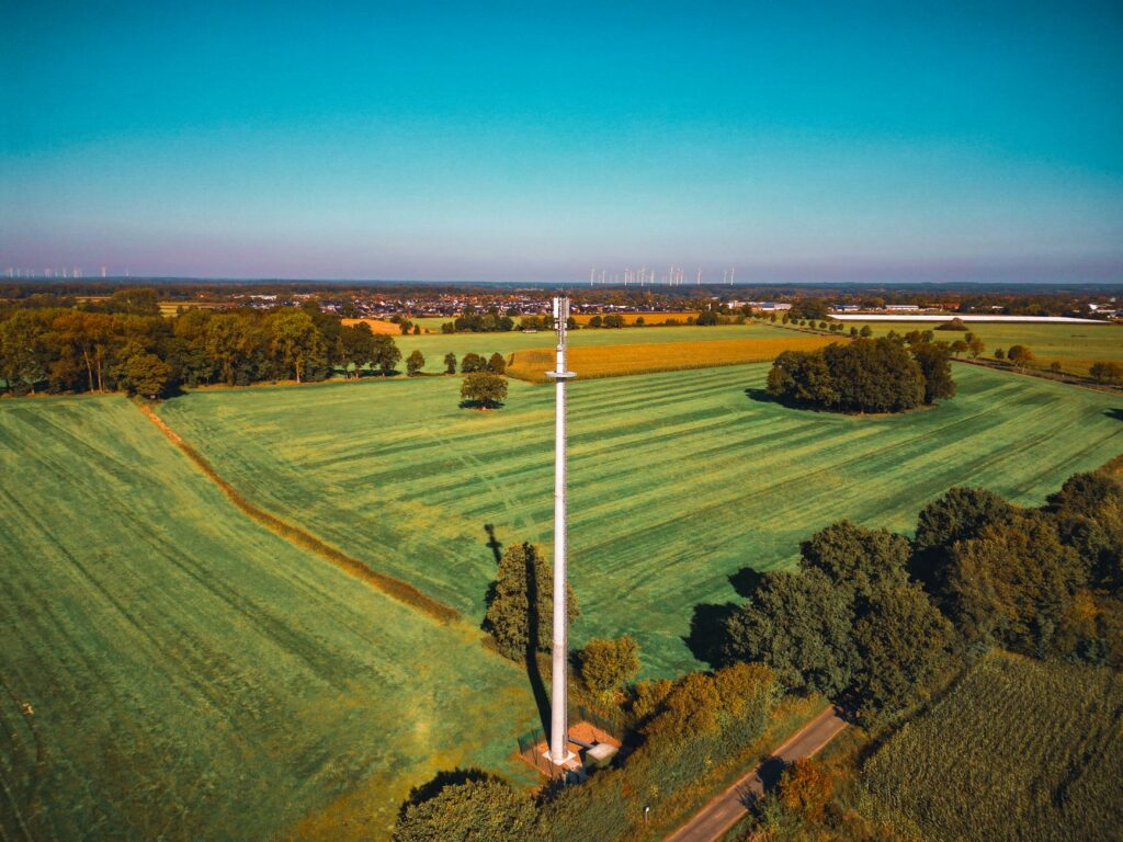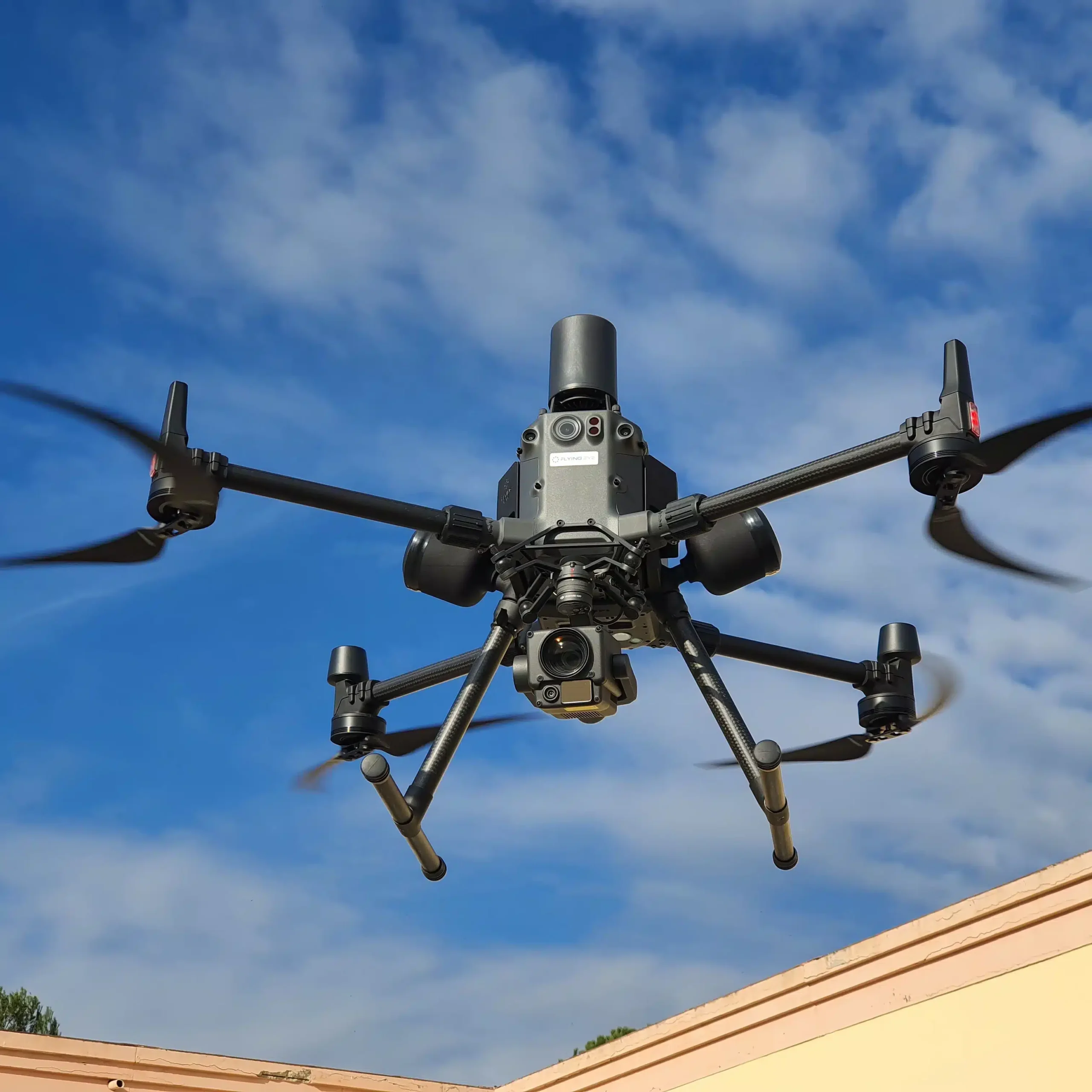
Best RTK Drone for Surveying: Compare Accuracy, Cost and Base Station Options
Choosing the best RTK drone for surveying takes more than lining up manufacturer specifications and picking the lowest advertised accuracy number. Here’s the deal: a receiver may promise centimeter-level positioning under ideal conditions, while the finished map still comes out wrong because of correction-link dropouts, poor satellite geometry, sloppy camera timing, rolling-shutter distortion, bad base coordinates or a mismatched coordinate reference system. For surveyors, engineering teams and UAV integrators, the real question is not simply, “Does this drone have RTK?” The better question is, “Can this entire workflow produce repeatable, defensible coordinates on the sites where we actually work?”
This guide breaks down the technical and commercial factors that matter in the field: horizontal and vertical accuracy, RTK fix continuity, camera requirements, payload weight, NTRIP versus a local base station, LoRa range, positioning update rate, software compatibility and total system cost. It also looks at two GNSS integration options—the lightweight HM-D20 UAV module and the HM-D13 field RTK receiver—and explains when it makes sense to buy a ready-to-fly survey platform, build a custom aircraft, use RTK with PPK backup or stick with a conventional ground-control workflow.
Table of Contents
- 👉 RTK Drone Selection at a Glance
- 👉 What Is an RTK Drone?
- 👉 How RTK Drone Accuracy Should Be Evaluated
- 👉 RTK vs PPK vs Ground Control Points
- 👉 How to Choose the Best RTK Drone
- 👉 Base Station, CORS, NTRIP and LoRa Options
- 👉 HM-D20 and HM-D13 Product Comparison
- 👉 RTK Drone Cost and Total Cost of Ownership
- 👉 How to Add RTK to a Custom UAV
- 👉 Recommended RTK Survey Workflow
- 👉 Best RTK Configuration by Application
- 👉 Limitations and Field Risks
- 👉 Procurement Checklist
- 👉 Final Recommendation
- 👉 Frequently Asked Questions
Quick answer: For most buyers, the best RTK drone is the one that combines a survey-grade camera, dependable exposure-event geotagging, stable fixed-solution performance and a correction method that works at the actual job site. A network-connected system is usually the fastest option where CORS coverage and cellular service are reliable. On remote or repeat projects, a local base station often earns its keep.
Working definition: An RTK drone is a UAV equipped with a real-time kinematic GNSS rover that receives correction data from a local base station or a CORS/NTRIP network. A proper survey setup also needs accurate camera timing, a suitable mapping sensor, sound coordinate management and independent checkpoints.
RTK Drone Selection at a Glance
Look, the best RTK drone is not automatically the aircraft with the smallest centimeter figure on the sales page. It is the complete package that stays fixed during the mission, assigns the right coordinate to each camera exposure, works with the correction source available on site and produces repeatable deliverables without blowing up the project budget.
| Buyer or operating condition | Best-fit configuration | Why it fits | Main issue to verify |
|---|---|---|---|
| Survey company wanting rapid deployment | Ready-to-fly RTK mapping drone | Integrated camera, flight planning, event timing and manufacturer support | Camera quality, processing compatibility and total ownership cost |
| Custom UAV developer | Lightweight all-in-one module such as the HM-D20 | 38.2 g listed weight with integrated GNSS, antenna and communication architecture | Flight-controller compatibility and camera-event synchronization |
| Remote project without dependable cellular service | Local RTK base with radio corrections | Independent of public mobile coverage | Radio range, terrain, legal frequency and base coordinates |
| Urban site with reliable CORS coverage | NTRIP-capable rover | Less field equipment and faster setup | Cellular availability, datum, mount point and baseline conditions |
| High-consequence survey deliverables | RTK plus PPK resilience and checkpoints | Adds post-processing recovery and independent validation | Raw-data support, event timing and processing workflow |
| Multiple rovers on a recurring site | One-to-many local base architecture | A shared correction source can reduce duplicated infrastructure | Radio capacity, rover compatibility and correction bandwidth |
Important: “Centimeter-level” receiver accuracy is not a guarantee of centimeter-level map accuracy. Final output also depends on the camera, image sharpness, flight plan, block geometry, coordinate system, surface conditions, processing settings and quality-control observations.
Check HM-D20 UAV Integration Specifications
Review HM-D13 Base and Rover Options
What Is an RTK Drone?
An RTK drone carries a GNSS rover receiver that observes satellite signals while receiving correction information from a reference source. That reference may be a local base station sitting on a known control point or a continuously operating reference station reached through the internet. By working with carrier-phase measurements and resolving integer ambiguities, the rover can produce a fixed RTK solution that is substantially more precise than ordinary standalone GNSS.
RTK rover, correction source and communication link
In the shop, we treat an RTK drone as a system with three core pieces. First comes the aircraft-side rover, including the receiver and antenna. Second is the correction source, whose coordinates must be known or established correctly. Third is the communication link that carries correction data to the aircraft, usually cellular NTRIP or a local radio such as LoRa.
A receiver specification by itself does not make a survey system. The aircraft still needs a suitable camera or mapping sensor, a flight controller, a dependable method for tying each exposure to GNSS time, mission-planning software and a processing workflow that does not scramble the datum, geoid or coordinate transformation.
Fixed, float and standalone positioning
- ✅ Fixed RTK: Integer ambiguities have been resolved. This is normally the status required for high-precision aerial mapping.
- ⚠️ Float RTK: Ambiguities remain unresolved or only partially resolved. Accuracy can be materially worse and is often less predictable.
- ⚠️ Standalone or differential GNSS: The rover does not have a valid fixed carrier-phase solution. Do not treat this as equivalent to verified RTK.
A solid survey workflow logs the solution state associated with every image event. Seeing a green RTK indicator before takeoff only proves what the receiver was doing at that moment. It does not prove that every photograph was captured while the system remained fixed.
Why RTK improves photogrammetry
Accurate camera-center coordinates can strengthen the photogrammetric block, speed up image alignment and reduce dependence on a dense field of ground control points. RTK also improves repeatability on recurring construction, stockpile and agricultural missions. What it does not do is eliminate the need for independent checkpoints when the accuracy of an orthomosaic, point cloud or elevation model has to be demonstrated.
How RTK Drone Accuracy Should Be Evaluated
Receiver position is not the same as deliverable accuracy
A serious accuracy review should separate four different things: the position calculated by the receiver, the physical location of the antenna phase center, the camera exposure-center position and the coordinates measured in the final deliverable. Each step can add its own error. Mixing them together is how impressive receiver numbers get turned into weak survey claims.
The GNSS antenna is usually mounted above or behind the camera rather than directly at the optical center. That physical separation is the lever arm. If the measured lever-arm offset and aircraft attitude are not handled correctly, an accurate antenna coordinate can still produce a biased camera coordinate. Timing adds another problem. A moving aircraft covers real distance between the instant the shutter fires and the epoch recorded in the position log.
Understanding 1 cm + 1 ppm
The HM-D20 and HM-D13 list horizontal RTK accuracy of 1.0 cm + 1 ppm and vertical accuracy of 1.5 cm + 1 ppm. The ppm term grows with baseline length. At a 1 km baseline, 1 ppm contributes roughly 1 mm. At 10 km, it contributes around 10 mm. At 20 km, it contributes about 20 mm.
That quick calculation is useful, but it is not the whole error budget. It does not include multipath, base-coordinate error, atmospheric conditions, camera timing or photogrammetric reconstruction. Vertical positioning is also usually weaker than horizontal positioning. Before comparing products, ask whether the accuracy figure is RMS, a confidence interval, a controlled test result or some other statistical measure.
Factors affecting field accuracy
- ⚙️ Satellite geometry and the number of usable constellations
- ⚙️ Multipath from buildings, vehicles, metal roofs and other reflective surfaces
- ⚙️ Tree canopy, terrain masking and partial sky obstruction
- ⚙️ Ionospheric and tropospheric conditions
- ⚙️ Distance between the rover and the reference station
- ⚙️ Correction age, latency, packet loss and reconnect behavior
- ⚙️ Antenna gain, orientation, mounting and nearby electronics
- ⚙️ Vibration, power-supply noise and electromagnetic interference
- ⚙️ Camera shutter type, focus, exposure and image interval
- ⚙️ Exposure-event timestamp latency
- ⚙️ Flight height, aircraft speed, overlap and ground sample distance
- ⚙️ Camera calibration and overall photogrammetric geometry
- ⚙️ Datum, reference-frame, coordinate-epoch, geoid and transformation errors
Is a 10 Hz update rate sufficient?
Both supplied receivers list a maximum update rate of 10 Hz. That means a properly configured receiver can output as many as ten position updates per second. It does not mean every image automatically gets the right coordinate. At 10 m/s, a timing error of 0.1 seconds represents roughly one meter of along-track travel. For survey work, use hardware event marking or a thoroughly tested timestamping method whenever the system supports it.
RTK vs PPK vs Ground Control Points
| Method | When corrections are applied | Main advantage | Main limitation | Best use |
|---|---|---|---|---|
| RTK | During the mission | Immediate fixed positions and efficient field operation | Depends on a reliable real-time correction link | Sites with stable cellular or radio corrections |
| PPK | After the mission | Can recover a precise trajectory despite correction-link interruptions | Requires raw observations, event timing and compatible software | Remote, long-corridor or interference-prone projects |
| GCP-based mapping | During photogrammetric processing | Strong control and independent block constraint | Additional field labor and visible targets are required | Conventional survey control or non-RTK aircraft |
| RTK/PPK plus checkpoints | Real time and/or post-processing | Operational resilience with independent validation | More equipment and workflow discipline | High-value, contractual or regulated deliverables |
RTK can reduce the number of ground control points, but it should not be sold as a reason to eliminate every ground observation. A checkpoint independently tests the finished output. A GCP constrains the photogrammetric model. The same point cannot honestly serve as both control and an independent checkpoint in one accuracy assessment.
Combining RTK and PPK is useful when a correction dropout could trigger an expensive return visit. Just do not assume PPK support because a receiver handles RTK or outputs NMEA and UBX messages. You still need raw observation recording, accurate exposure-event timing, compatible base data and processing software that can use those records.
How to Choose the Best RTK Drone for Surveying
Camera and shutter performance
The camera matters every bit as much as the GNSS receiver. A mechanical or global shutter is generally the safer choice for aerial photogrammetry because a rolling shutter exposes different image rows at different times. Compare sensor size, lens quality, distortion, image interval, exposure control, focus stability and access to a hardware exposure signal.
A centimeter-grade coordinate cannot rescue a blurry photograph. It also cannot repair unstable focus or severe rolling-shutter distortion after the fact. The camera needs enough ground resolution to identify the required features while still giving the aircraft practical coverage and endurance.
Payload, endurance and coverage
Receiver weight affects flight time, center of gravity and usable payload. The HM-D20 has a listed mass of 38.2 g, which makes it relevant for small custom UAVs. The installed system will weigh more once wiring, mounting hardware, weather protection and supporting electronics are included. Test endurance with the complete payload rather than relying on bare-module weight.
Constellation and frequency support
The supplied HM-D20 and HM-D13 specifications list L1/L5 dual-frequency RTK and support for GPS, BeiDou, Galileo, QZSS, GLONASS and IRNSS. Multi-constellation tracking can improve satellite availability around partial obstructions. The signals actually available still depend on location, antenna response, firmware configuration and what the base station or correction network transmits.
Correction compatibility
Procurement teams should verify accepted correction messages, NTRIP client behavior, CORS credentials, mount-point compatibility, SIM requirements, cellular bands, reconnect logic and receiver behavior after correction loss. If LoRa is involved, confirm the exact radio frequency and local spectrum rules. A listed default of 915 MHz is not automatically legal everywhere.
Flight and processing software
The platform should fit the organization’s real production environment. Check terrain following, corridor mapping, crosshatch missions, oblique capture, event logs, coordinate-system export and quality reporting. For high-volume operators, raw GNSS access, API support, offline operation and recurring software-license costs can be just as important as the aircraft hardware.
Mapping payload ecosystem
Photogrammetry works well on visible, textured surfaces. LiDAR may be the better tool for certain vegetation, structural and terrain jobs. Teams comparing payloads can review this guide to what LiDAR technology is and the detailed dToF versus iToF sensor guide. Developers working on obstacle detection and autonomous navigation may also find the guide to stereo vision camera navigation useful.
Component research may include established photonics suppliers such as ams OSRAM and LiDAR manufacturers such as Ouster. These are contextual references, not blanket endorsements. Timing, field of view, mass, power draw, software and mechanical compatibility still have to be proven at the system level.
Base Station, CORS, NTRIP and LoRa Options
Local RTK base station
A local base can sit on a known survey point, or its coordinates can be established through an observation procedure appropriate to the job. It gives the crew control over the correction source, keeps the baseline short and may serve several rovers on a recurring site. It is especially useful where cellular coverage is poor or a third-party service cannot be trusted to remain available.
Here’s the catch: the base coordinates must be good enough for the required absolute accuracy. A short average of an autonomous position may produce a tidy-looking, internally consistent project that is shifted in the real coordinate system. Crews also need to measure antenna height correctly, secure the base, provide stable power and preserve a clear radio path.
CORS and NTRIP
NTRIP delivers GNSS correction data over the internet. A CORS provider may send corrections from a physical reference station or create a network solution such as a virtual reference station. Network RTK can save setup time and reduce field equipment, but the crew still needs to verify coverage, mount-point type, reference frame, coordinate epoch, subscription cost and reconnect behavior.
Test cellular coverage at the actual site. A colored coverage map from a carrier is not a field test. Project records should identify the correction service, mount point and reference system used so the work can be audited or repeated later.
LoRa correction links
The supplied HM-D20 and HM-D13 specifications list a default LoRa frequency of 915 MHz, communication range up to 6 km, one-base-to-one-or-multiple-rover networking and a maximum listed rover count of 4096. Treat the 6 km number as a product specification, not a guaranteed operating radius.
Terrain, antenna elevation, buildings, trees, interference, aircraft orientation, transmit settings and local power limits all affect usable range. The 915 MHz configuration may not be permitted in every country. Select the proper regional hardware, run a site-specific range test and monitor correction age during the mission.
Practical correction-source decision
- ✅ Choose NTRIP where reliable cellular service and a compatible CORS network are available.
- ✅ Choose a local base for remote work, recurring sites, short baselines or stronger control over the correction source.
- ✅ Choose RTK with PPK resilience when real-time continuity is uncertain and the hardware explicitly supports raw-data processing.
- ✅ Use independent checkpoints whenever the deliverable needs a documented accuracy statement.
HM-D20 and HM-D13 RTK Receiver Product Comparison
Product disclosure: The HM-D20 and HM-D13 are GNSS/RTK positioning components intended for UAV, robotic and field-system integration. They are not ready-to-fly drones. They do not include an airframe, propulsion system, mapping camera, flight controller or photogrammetry package. Confirm the selected 4G or LoRa variant, included accessories, environmental rating, correction format and firmware functions before ordering.
| Specification | HM-D20 RTK GNSS module | HM-D13 RTK GNSS receiver |
|---|---|---|
| Positioning capability | L1/L5 dual-frequency RTK | L1/L5 dual-frequency RTK |
| Horizontal accuracy | 1.0 cm + 1 ppm | 1.0 cm + 1 ppm |
| Vertical accuracy | 1.5 cm + 1 ppm | 1.5 cm + 1 ppm |
| Maximum update rate | 10 Hz | 10 Hz |
| RTK time to first fix | 45 seconds | 45 seconds |
| Satellite systems | GPS, BeiDou, Galileo, QZSS, GLONASS, IRNSS | GPS, BeiDou, Galileo, QZSS, GLONASS, IRNSS |
| Tracking channels | 200 | Not stated in the supplied specification |
| Cold start / hot start | 28 seconds / 1 second | 28 seconds / 1 second |
| Antenna system gain | 40 dB | 40 dB |
| 4G correction option | CORS / NTRIP | CORS / NTRIP |
| LoRa default frequency | 915 MHz | 915 MHz |
| Listed LoRa range | Up to 6 km | Up to 6 km |
| LoRa networking | One base station to one or multiple rovers | One base station to one or multiple rovers |
| Maximum listed rovers | 4096 | 4096 |
| Dimensions / weight | Φ54.5 × 53 mm / 38.2 g | Φ152 × 67.9 mm / 550 g for the listed base-station configuration |
| Operating voltage | 5 V ±0.5 V | 5 V |
| Data and interface | 8-pin / NMEA / UBX | 5-pin XH2.54 / NMEA / UBX |
| Magnetometer | QMC5883L using SCL/SDA | Not stated in the supplied specification |
| Best-fit role | Lightweight UAV, autonomous vehicle or robotic rover integration | Field receiver or local-base-oriented deployment |
Specifications may change. Confirm the selected hardware, radio and communication variant before purchase.
HM-D20: Lightweight RTK GNSS Module for Drone Integration
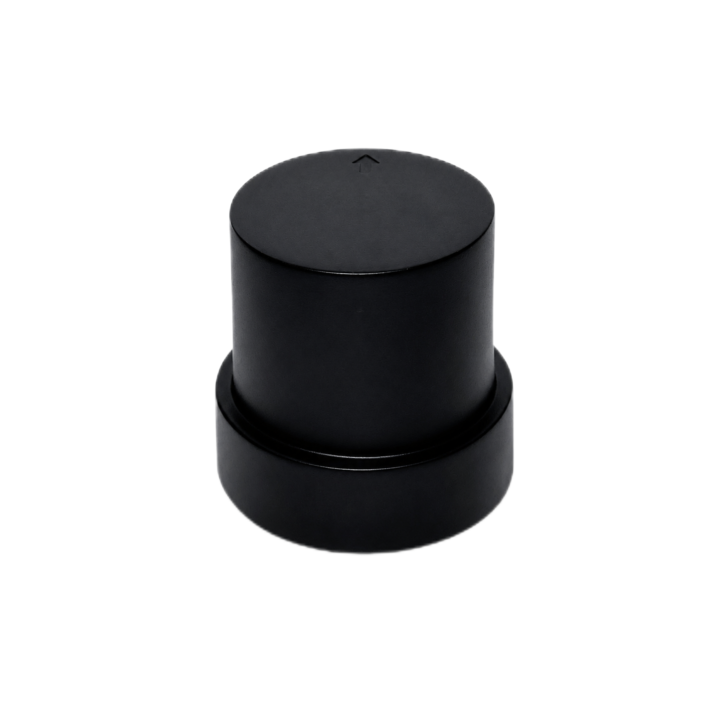
Of the two products discussed here, the HM-D20 is the more natural aircraft-side choice. It combines a helical antenna, GNSS positioning and communication architecture in a package measuring Φ54.5 × 53 mm and weighing 38.2 g. The listed 5 V ±0.5 V supply, 8-pin interface, NMEA and UBX support, 200 tracking channels and QMC5883L magnetometer make it relevant for custom UAV, autonomous vehicle, robotics and mapping projects.
The module supports L1/L5 dual-frequency RTK with listed horizontal accuracy of 1.0 cm + 1 ppm, vertical accuracy of 1.5 cm + 1 ppm, a maximum 10 Hz update rate and a 45-second RTK time to first fix. Supported satellite systems include GPS, BeiDou, Galileo, QZSS, GLONASS and IRNSS. Cold and hot starts are listed at 28 seconds and 1 second, with antenna system gain of 40 dB.
Correction options include a 4G version for CORS/NTRIP and a LoRa version with a default frequency of 915 MHz. Listed LoRa range is up to 6 km, with one base supporting one or multiple rovers and a maximum stated rover count of 4096. Those are product specifications. Real-world link performance has to be tested where the system will operate.
Do not assume the HM-D20 automatically handles camera geotagging just because it outputs GNSS data. A custom survey aircraft still needs exposure-event synchronization, lever-arm calibration, flight-controller integration, clean power and a mapping camera that can hold focus and capture sharp images. Documentation is available for the HM-D20 GNSS RTK receiver module.
View Product Details & Pricing ➔
HM-D13: Field Receiver and Base-Station-Oriented RTK Deployment
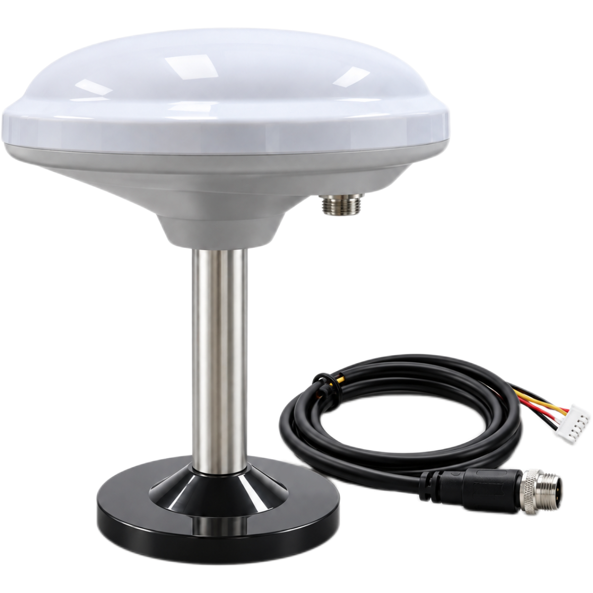
The HM-D13 is a multiband RTK survey receiver intended for field mapping, robots, UGVs, USVs, agriculture and UAV support. Its listed base-station configuration measures Φ152 × 67.9 mm and weighs 550 g. In practical terms, that makes it better suited to ground-side infrastructure than a weight-sensitive small drone, although the broader architecture can support several autonomous-platform applications.
The HM-D13 shares the listed L1/L5 dual-frequency RTK capability, 1.0 cm + 1 ppm horizontal accuracy, 1.5 cm + 1 ppm vertical accuracy, 10 Hz maximum update rate and 45-second RTK time to first fix. It supports GPS, BeiDou, Galileo, QZSS, GLONASS and IRNSS. Cold and hot starts are listed at 28 seconds and 1 second, and antenna system gain is 40 dB.
Operating voltage is listed at 5 V. Data connectivity uses a 5-pin XH2.54 interface with NMEA and UBX. Correction options include CORS/NTRIP through a 4G version or LoRa with the same listed 915 MHz default frequency, up-to-6 km range, one-to-many networking and 4096 maximum listed rovers.
Product information also describes outdoor operation from -40°C to 85°C and water-resistance support for wet conditions. Ask for the exact environmental rating, enclosure specification and certification for the configuration being purchased. A general water-resistance statement is not the same thing as a documented IP rating.
View Product Details & Pricing ➔
RTK Drone Cost and Total Cost of Ownership
Product pricing changes with communication variant, accessories, quantity and region, so current numbers should come from the product page or a formal quotation. More important, do not compare systems using the receiver or aircraft price alone. The inexpensive unit on the purchase order can become the expensive unit after engineering, software and repeat field visits are counted.
- ⚙️ Airframe and propulsion: Include motors, propellers, landing gear, redundancy and actual payload limits.
- ⚙️ RTK rover and antenna: Include the receiver, mounting, connectors and correction interface.
- ⚙️ Mapping payload: Account for the camera, LiDAR, multispectral sensor or other payload.
- ⚙️ Correction source: Include a local base, CORS subscription, SIM card and radio hardware.
- ⚙️ Software: Include flight planning, photogrammetry, point-cloud processing and recurring licenses.
- ⚙️ Power and spares: Count batteries, chargers, field power, replacement cables and propellers.
- ⚙️ Integration engineering: Budget for mechanical design, wiring, firmware, timing work and testing.
- ⚙️ Training and validation: Include staff time, test sites, checkpoints and documentation.
- ⚙️ Maintenance and compliance: Include repairs, calibration, insurance and regulatory obligations.
- ⚙️ Remobilization risk: Estimate the cost of returning after a failed correction link, missing log or bad image set.
Total ownership cost = acquisition + integration + correction service + software + batteries and maintenance + processing hardware or cloud use + training + expected remobilization cost.
A low-cost custom UAV can get expensive fast if the engineering team has to develop exposure synchronization, vibration isolation, correction handling and coordinate export from scratch. On the other hand, custom systems can reduce fleet-scale cost and offer more payload flexibility when the organization already has experienced engineers and a repeatable integration process.
How to Add RTK to a Custom UAV
Mechanical integration
The GNSS antenna needs a clear view of the sky, stable orientation and reasonable separation from motors, high-current wiring, switching regulators and powerful transmitters. The mounting should be rigid enough to preserve the measured lever arm while controlling vibration. It also needs protection from weather, propeller contact and hard landings without blocking satellite reception.
Measure the three-dimensional offset between the antenna reference point and the camera exposure center. Write down the axis convention. In the shop, sign errors and swapped axes are common enough that they should be treated as expected integration risks rather than rare mistakes.
Electrical integration
The HM-D20 requires a listed 5 V ±0.5 V supply, while the HM-D13 lists 5 V. Use a clean regulated source with secure connectors and proper grounding. Do not assume an available flight-controller power rail has enough current capacity or acceptable noise. Test voltage stability with the motors, payload and radios operating under representative load.
Data and correction integration
The HM-D20 uses a listed 8-pin interface with NMEA and UBX. The HM-D13 uses a 5-pin XH2.54 interface with NMEA and UBX. Confirm signal voltage levels, pin assignments, baud rate, message selection, update rate, correction input path, time source and flight-controller driver support before connecting hardware.
The finished system should log position, RTK solution state, correction age and exposure events. Every image must be tied to the correct GNSS epoch. Hardware event input is preferred when available, but any timing method can work only after its latency and repeatability have been measured.
Magnetometer considerations
The HM-D20 includes a QMC5883L magnetometer using SCL/SDA. Motors, power conductors, steel hardware and switching currents can distort the magnetic field around the sensor. Test heading performance with the complete aircraft powered, armed and operating. A clean bench calibration may look perfect and still fail once current starts flowing through the propulsion system.
Integration validation protocol
- ⚙️ Perform an open-sky static test and review fixed-solution stability.
- ⚙️ Interrupt the correction link and document float status, reconnect time and recovery behavior.
- ⚙️ Run a restrained power-system and electromagnetic-interference test.
- ⚙️ Conduct a hover test and inspect vibration, heading and GNSS logs.
- ⚙️ Run a dynamic trajectory test at representative flight speed.
- ⚙️ Fly repeated mapping missions over surveyed checkpoints.
- ⚙️ Review RTK status and correction age for every recorded image event.
- ⚙️ Verify datum, geoid, coordinate transformation and vertical units.
- ⚙️ Test failover, geofence and return-to-home behavior.
- ⚙️ Record firmware, configuration, antenna offsets and software versions.
Recommended RTK Drone Survey Workflow
- ⚙️ Define tolerances: Set horizontal and vertical deliverable requirements before buying or configuring equipment.
- ⚙️ Select the coordinate system: Document the horizontal reference frame, vertical datum, geoid, coordinate epoch and units.
- ⚙️ Review the site: Identify airspace restrictions, terrain, obstructions, reflective structures and weak cellular areas.
- ⚙️ Select corrections: Confirm NTRIP coverage or choose a secure base location with open sky and a workable radio path.
- ⚙️ Verify base coordinates: Use known survey control or an approved observation procedure matched to the required tolerance.
- ⚙️ Measure antenna height: Record the antenna reference point, measurement method and units.
- ⚙️ Confirm fixed status: Wait for a fixed solution and check correction age before launching.
- ⚙️ Place checkpoints: Distribute independent checkpoints across the site and through the available elevation range.
- ⚙️ Plan image geometry: Set forward overlap, side overlap, flight height, speed and oblique coverage for the surface being mapped.
- ⚙️ Monitor the mission: Watch solution state, correction age, satellite count, battery health and camera operation.
- ⚙️ Preserve records: Keep base, rover, flight, image-event and correction-source logs.
- ⚙️ Process consistently: Apply the intended coordinate system, camera model and transformation settings.
- ⚙️ Inspect the model: Review alignment, residuals, surface noise, image quality and weak geometry.
- ⚙️ Validate externally: Compare final coordinates against checkpoints that were not used in the adjustment.
- ⚙️ Archive the quality record: Store settings, firmware versions, logs, checkpoint results and processing reports.
Best RTK Configuration by Application
Topographic mapping
Use a survey-appropriate camera, dependable exposure timing, RTK/PPK resilience where available and checkpoints spread across elevation changes. For topographic work, vertical accuracy, surface visibility and vegetation are often more important than the receiver’s nominal horizontal number.
Construction progress
Prioritize repeatable flight plans, stable coordinate control, quick processing and compatibility with change-detection tools. A permanent local base or verified site-control network can be useful for recurring work, provided the coordinates and physical stability of the installation are managed.
Corridor and utility mapping
Long linear missions need endurance, terrain following and careful correction planning. As the aircraft gets farther from a local base, the ppm term increases and radio continuity may become harder to maintain. Cross-track lines or oblique images can improve geometry where the site and flight rules allow them.
Agriculture
Coverage rate, multispectral compatibility and repeatable georeferencing are the main concerns. Be clear about whether the operation needs relative repeatability, absolute positioning or both. General crop mapping and automated machine guidance may have very different accuracy and latency requirements.
Stockpile and volume measurement
Use enough overlap and oblique imagery to capture steep faces while maintaining a safe stand-off distance. RTK can improve repeatability between surveys, but shiny, uniform or textureless material can still give photogrammetry trouble. Good coordinates do not create image texture where none exists.
Custom robotics and multi-rover sites
The one-base-to-multiple-rover architecture listed for the HM-D20 and HM-D13 can support fleet deployments. The stated maximum of 4096 rovers is a networking specification. Practical capacity still depends on correction bandwidth, required update rate, interference, radio settings and the operator’s ability to manage that many field devices.
RTK Drone Limitations and Field Risks
| Risk | Possible consequence | Mitigation |
|---|---|---|
| Correction dropout | Float or standalone image positions | Improve the link, shorten the baseline and use PPK fallback where supported |
| Multipath | Biased or unstable coordinates | Use open-sky base placement and avoid reflective obstructions |
| Wrong datum | Consistent but displaced output | Verify reference frame, coordinate epoch, geoid and transformation |
| Incorrect base coordinates | The entire project is shifted | Use surveyed coordinates or an approved observation method |
| Poor event timing | A position is assigned to the wrong exposure time | Use hardware event marking and test system latency |
| Rolling shutter | Geometric distortion | Use a suitable shutter, slower flight or a validated correction model |
| Magnetic interference | Heading instability | Improve placement and test under operating power |
| LoRa obstruction | Reduced range and aged corrections | Raise antennas, improve line-of-sight and perform a radio survey |
| Weak imagery | Noisy or failed reconstruction | Correct focus, exposure, overlap, shutter and flight height |
| No checkpoints | Unsupported accuracy claim | Reserve surveyed points for independent validation |
RTK can make positioning faster and more repeatable. It does not replace professional judgment, aviation compliance, legal survey requirements or project-specific quality assurance. If a deliverable has contractual or public-safety consequences, the validation plan matters just as much as the receiver specification.
RTK Drone Procurement Checklist
- ✅ Is the item a complete aircraft, rover module, base station or correction service?
- ✅ What are the specified horizontal and vertical fixed-RTK accuracies?
- ✅ Are those values stated as RMS, CEP, confidence level or another metric?
- ✅ Which GNSS frequencies and constellations are supported?
- ✅ How reliably does the receiver hold a fixed solution in the target environment?
- ✅ Does the system support CORS/NTRIP and the correction messages you need?
- ✅ Is a local base included, optional or sold separately?
- ✅ Which radio frequency is used, and is it legal in the operating country?
- ✅ What range has been demonstrated under conditions similar to the job site?
- ✅ Can the receiver record raw observations for a complete PPK workflow?
- ✅ Is camera-event timing hardware-based and documented?
- ✅ Is the camera shutter suitable for moving aerial mapping?
- ✅ What are the actual payload, endurance and wind limitations?
- ✅ Which mission-planning and processing platforms are supported?
- ✅ Can the operator export solution-state, correction-age and quality logs?
- ✅ Which datum, geoid and coordinate-transformation tools are available?
- ✅ What environmental protection and operating-temperature range are documented?
- ✅ Are an SDK, sample code, manuals and firmware updates available?
- ✅ What is the expected three-year or five-year ownership cost?
- ✅ How will the final output be checked against independent survey points?
Final Recommendation: Which RTK Configuration Is Best?
Best for a survey company seeking low integration risk: Choose a ready-to-fly mapping drone with a survey-appropriate camera, verified exposure synchronization, supported processing software and documented RTK/PPK capability. It usually costs more up front, but it reduces engineering time and commissioning risk.
Best for a lightweight custom UAV: The HM-D20 is the stronger fit of the two supplied components because it weighs 38.2 g and combines antenna, positioning and communication functions in a compact package. The engineering team still needs to validate flight-controller compatibility, correction input, event timing, power quality and lever-arm calibration.
Best for remote or recurring operations: A local base gives the crew more control than CORS/NTRIP when cellular service is unreliable. The HM-D13’s listed base-station configuration makes it more relevant to that ground-side role.
Best for urban operations with dependable network coverage: An NTRIP-capable rover can reduce field equipment and setup time, provided the CORS reference frame, mount point, service area and reconnect behavior are understood.
Best for high-consequence deliverables: Use RTK with raw-data and PPK resilience where those functions are explicitly supported, then verify the work with independently surveyed checkpoints. The best RTK drone is the one that can prove the accuracy of its deliverables—not the one with the brightest fixed-status icon.
Before selecting a receiver or aircraft, document the required accuracy, camera payload, expected baseline, correction availability, coordinate system and integration interfaces. Then compare the available HM-D20 and HM-D13 configurations against that job definition and test the chosen system under realistic operating conditions.
View HM-D20 for Lightweight UAV Integration
View HM-D13 for Field RTK Deployment
Frequently Asked Questions About RTK Drones
What is the best RTK drone for photogrammetry on a limited budget?
Do I need an RTK base station, or can I use an NTRIP provider?
Can I add RTK to a minidrone or custom FPV mapping drone?
Does an RTK drone guarantee centimeter-level map accuracy?
Is RTK better than PPK for drone surveying?
Can RTK drones eliminate ground control points?
Will a LoRa RTK correction link work reliably at 6 km?
Is a 10 Hz GNSS update rate sufficient for drone mapping?
📚 References & Further Reading
-
- Industry Standard: ams OSRAM photonics and sensing resources
- Product Reference: HM-D20 all-in-one RTK GNSS module
- Product Reference: HM-D13 RTK GNSS receiver