


LiDAR Sensor UAV Buying Guide: Lightweight dToF Sensing for Drones
Here’s the deal: selecting a LiDAR sensor for a UAV is not as simple as buying the unit with the longest advertised range. On an aircraft, every gram, watt, frame, connector, and degree of field of view matters. Those details affect flight endurance, obstacle coverage, controller latency, center of gravity, and ultimately whether the finished drone behaves predictably. A sensor that looks excellent on a test bench may lose usable range in direct sunlight. A survey-grade unit may deliver impressive data but still be too heavy, power-hungry, or complicated for a compact navigation drone.
This guide explains how lightweight direct time-of-flight, or dToF, sensing works and how to compare UAV LiDAR modules for altitude hold, terrain following, proximity detection, obstacle avoidance, autonomous landing, inspection, and robotic perception. It also takes a practical look at the HM-LD1 solid-state dToF LiDAR, a 28 g depth sensor with a 60° × 45° field of view, 40 × 30 depth resolution, 10 fps output, and UART, UDP, and UVC connectivity. Use the buying criteria, integration checklist, specification table, and application guidance below to decide whether it fits your aircraft, mission, and operating environment.
Table of Contents
- 👉 What Is a UAV LiDAR Sensor?
- 👉 How dToF LiDAR Works on a Drone
- 👉 Major UAV LiDAR Applications
- 👉 UAV LiDAR Buying Criteria
- 👉 Sunlight, Reflectivity, and Real-World Range
- 👉 HM-LD1 Specifications
- 👉 Payload, Power, and Flight-Time Planning
- 👉 FOV, Resolution, and Frame Rate
- 👉 Interfaces and UAV Integration
- 👉 Mounting and Calibration
- 👉 LiDAR Compared with Other Drone Sensors
- 👉 Where HM-LD1 Fits Best
- 👉 Pre-Purchase Validation Checklist
- 👉 Final Recommendation
- 👉 Frequently Asked Questions
What Is a UAV LiDAR Sensor?
A UAV LiDAR sensor emits optical energy, measures the returned signal, and converts that measurement into distance, depth, or point-cloud data. LiDAR stands for light detection and ranging, but that label covers several product categories with very different outputs, ranges, payload requirements, and integration demands. Before comparing specifications, define the measurement job. In the shop, that first step prevents a lot of expensive rework.
Not Every Drone LiDAR Performs the Same Job
A single-point rangefinder reports distance in one direction and may be perfectly adequate for basic altitude or proximity measurement. A multi-zone solid-state depth sensor measures many regions across a field of view, allowing the host system to distinguish local surfaces, clearance areas, and coarse obstacle shapes. A scanning mapping LiDAR gathers denser spatial data. A complete survey payload goes further by combining a scanner with precision positioning, inertial sensing, timing, storage, and post-processing software.
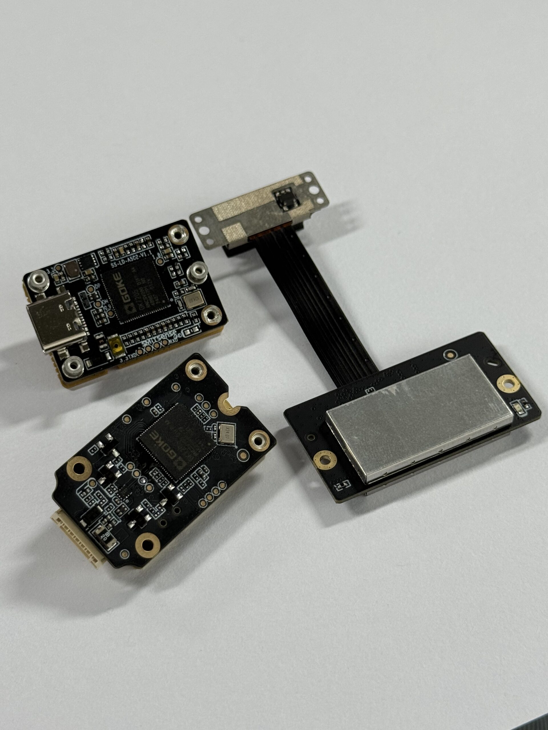
Look, comparing all of those categories by maximum range alone will lead you straight into a bad buying decision. A 40 × 30 depth module provides spatial information that a one-dimensional rangefinder cannot, but it does not deliver the point density, operating altitude, or georeferenced output expected from a survey-grade airborne scanner. The right choice depends on whether the aircraft needs local perception or a professional mapping deliverable.
Depth Data Versus Survey Data
Depth data is normally interpreted in the sensor or vehicle coordinate frame. It can tell a controller that a surface is a certain distance below the aircraft or that an object occupies the left side of the forward field of view. That is useful information for navigation and clearance logic, but it is not automatically a survey product.
Survey data usually has to be transformed into an accurate geographic coordinate system. That process commonly requires precision GNSS, a high-grade inertial measurement unit, exact timestamp synchronization, boresight calibration, trajectory processing, georeferencing, point-cloud correction, and specialized export tools. HM-LD1 is primarily a compact depth-perception module. It can support local ranging and robotic perception, but it should not be presented as a complete UAV surveying system.
How dToF LiDAR Works on a Drone
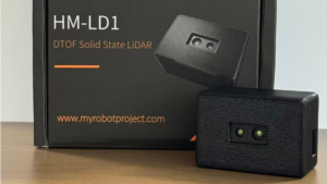
Time-of-Flight Measurement Principle
Direct time-of-flight sensing measures how long emitted light takes to travel to a target and return to the receiver. The basic relationship is distance = speed of light × round-trip time ÷ 2. The division by two matters because the measured interval includes both the outbound and return paths.
The equation is simple. Building a dependable airborne measurement system around it is not. Practical performance depends on timing precision, optical design, receiver sensitivity, target reflectivity, ambient illumination, calibration, filtering, and the angle at which the emitted light strikes the surface. Those variables are why indoor and outdoor range figures need to be evaluated separately.
What SPAD Technology Contributes
HM-LD1 uses SPAD dToF technology. A SPAD, or single-photon avalanche diode, is designed to detect extremely low optical signal levels. The system accumulates and processes photon-arrival events to estimate the return timing associated with a target. A strong optical return is generally easier to separate from noise. Bright ambient light adds background photons, which the sensor and its processing chain must reject.
Because HM-LD1 measures multiple zones, it can produce a depth image instead of reporting a single distance. Those measurements can also be represented as 3D point-cloud data. For a compact module, that opens the door to region-based proximity logic, environmental perception, robotic navigation, and visual development tools.
Why Solid-State Construction Matters
A solid-state architecture is attractive when compact dimensions, low mass, moderate electrical power, and installation without a mechanically rotating scanner are priorities. That makes the format relevant to small drones, mobile robots, and embedded systems with tight payload limits. Still, “solid-state” is not a substitute for a vibration specification. It does not automatically prove shock resistance, service life, or environmental durability. Aircraft-level vibration, thermal, shock, and endurance testing remain necessary.
Major Applications for a LiDAR Sensor on a UAV
Altitude Hold and Low-Altitude Ranging
A downward-facing drone LiDAR sensor can provide a direct distance-to-surface measurement that supplements pressure-based altitude estimates. This can help during low-altitude inspection, indoor flight, takeoff, landing, and operations where local clearance matters more than elevation above sea level. Test it over the actual surfaces used in the mission. Water, glass, dark roofing, vegetation, steep slopes, and glossy finishes do not all return light the same way.
Terrain Following
Terrain following takes more than reading the center zone and sending that number to the autopilot. The processing system may need to select a valid region of interest, reject outliers, estimate surface slope, compensate for aircraft roll and pitch, and smooth noisy readings without adding too much control lag. A 60° × 45° field of view provides multiple depth zones across the scene, but the observed footprint grows with distance and changes as the aircraft rotates.
Obstacle Avoidance and Proximity Detection
Forward-, rear-, side-, or downward-facing modules can monitor selected areas around a drone. One forward sensor does not provide full aircraft protection because it only sees objects within its optical field of view. Multiple modules, or fusion with cameras, radar, ultrasonic sensors, and other LiDAR devices, may be needed. Thin wires, small branches, dark composites, and objects covering only a few depth zones deserve dedicated testing.
Landing Assistance
Depth images can help estimate distance to an approaching surface, identify major height changes, and monitor local clearance during descent. The module supplies measurements; it is not a complete or certified autonomous landing system. Flight software still has to determine which zones are valid, assess surface consistency, compensate for attitude, and define safe behavior when readings disappear or conflict.
Infrastructure and Robotic Inspection
HM-LD1 can support short-range perception near bridges, expressways, dams, warehouses, enclosed industrial spaces, and structures that are difficult or hazardous for people to approach. Its published outdoor range is up to 8 m under the stated conditions. That makes it relevant to local inspection and proximity awareness, but it is not equivalent to a long-range airborne mapping scanner.
SLAM and Sensor Fusion
Low-resolution depth data can contribute to experimental SLAM, local occupancy analysis, or navigation when combined with an IMU, camera, wheel odometry, GNSS, or other measurements. Results depend on scene geometry, aircraft motion, frame rate, estimator design, calibration, and synchronization. The point-cloud output is useful, but its presence does not guarantee dependable SLAM. Benchmark the complete perception pipeline under realistic motion and lighting.
How to Choose a LiDAR Sensor for a UAV
1. Define the Detection Task
Start by deciding whether the project needs one-dimensional altitude, multi-zone obstacle detection, terrain profiles, landing support, indoor navigation, outdoor inspection, or dense survey mapping. Then define how the data will be used: visualization, pilot assistance, development testing, or autonomous closed-loop control. Those are not interchangeable jobs, and each carries a different validation burden.
2. Separate Indoor and Outdoor Range
Do not pull the largest number from the data sheet and call it the working range. HM-LD1 is specified for 0.5–25 m indoors and 0.2–8 m outdoors. Product information also associates the longer figure with indoor or nighttime operation and the 8 m figure with daytime outdoor conditions. Strong sunlight, unfavorable targets, and installation geometry can reduce the usable distance.
3. Evaluate Field of View and Blind Zones
Review horizontal and vertical FOV along with minimum range, fuselage edges, propellers, landing gear, brackets, cables, and protective windows. HM-LD1 has a 60° horizontal by 45° vertical FOV. If several sensors are installed, calculate their overlap and remaining blind zones. Nominal angles on a drawing do not automatically create complete protection around a moving aircraft.
4. Match Resolution to Object Size
A 40 × 30 output contains 1,200 depth zones. Detection depends on how many zones a target occupies, not merely whether the target falls inside the nominal field of view. A broad wall can cover many zones. A cable, twig, or narrow pole may cover too little of the scene for reliable detection. Test the smallest required obstacle at the longest required range.
5. Check Update Rate Against Vehicle Speed
HM-LD1 provides 10 fps, which corresponds to nominal frame spacing of about 100 milliseconds. At 5 m/s, a drone travels roughly 0.5 m during one nominal frame interval. That occurs before communication, filtering, decision-making, controller response, and physical maneuver time are included. It is a useful planning example, not a guaranteed stopping-distance calculation.
6. Budget Mass and Power
The module weighs 28 g and consumes 1.2 W. The installed system may also need a bracket, cable, converter, protective cover, companion computer, and thermal provisions. Include every one of those parts in the payload and energy budget. Also account for where the sensor sits relative to the aircraft’s center of gravity.
7. Verify Interfaces and Software
HM-LD1 supports UART, UDP, and UVC. SDK support is listed for x86 Windows, x86 Linux, and Arm Linux. That sounds flexible, and it is, but connectivity is only the first layer. Before committing to the module, request protocol documentation and verify packet structure, timestamps, data units, invalid-zone handling, host compatibility, startup behavior, and software licensing.
8. Review Environmental and Supply Requirements
Compare the published operating range with the temperature inside the actual enclosure. Review vibration, contamination, condensation, optical-window behavior, connector retention, lead times, technical support, product-change controls, and OEM or ODM requirements. Unless an ingress-protection rating is documented, do not assume the module is weatherproof.
How Sunlight, Reflectivity, and Target Geometry Affect Range
Ambient Light
Strong sunlight adds optical background energy at the receiver and can reduce the signal-to-noise ratio of the returned pulse. HM-LD1 product information describes measurement to 8 m outdoors on a clear summer day under an assumed 80,000 lux condition. Treat that as a referenced test context, not a universal guarantee. Aircraft orientation, direct solar exposure, target properties, optical contamination, and processing thresholds can all change the result.
Target Reflectivity
Light-colored or optically reflective surfaces often return a stronger signal than dark, absorptive, or irregular materials. A favorable target measured in a controlled test should not be used to predict performance on matte black composites, wet asphalt, foliage, glass, or water. In the shop, qualify the sensor with the darkest and least cooperative target the mission must detect.
Angle of Incidence
A surface viewed nearly perpendicular to the optical path may return more energy toward the receiver than one viewed at a steep angle. Drone pitch, roll, yaw, terrain slope, and mounting direction all influence the usable geometry. Even a nominally flat surface can contain edges or mixed-depth regions that produce different values across neighboring zones.
Weather and Optical Contamination
Fog, rain, spray, dust, condensation, and a dirty cover can attenuate, scatter, or prematurely reflect emitted light. If the sensor sits behind a protective window, test that window for optical transmission, internal reflections, distortion, crosstalk, temperature effects, and contamination. Do not infer an IP rating or all-weather capability without documentation.
HM-LD1 Solid-State dToF LiDAR Specifications
The HM-LD1 solid-state dToF LiDAR provides real-time depth images and 3D point-cloud data in a 28 g module intended for drones, mobile robots, cameras, security systems, embedded products, and development platforms. Potential uses include UAV altitude hold, terrain following, distance detection, obstacle avoidance, autonomous-navigation development, robotic vision, autofocus, presence detection, object recognition, volume measurement, and zone monitoring.
The module supports UART, UDP, and UVC interfaces for connection to flight controllers, PCs, Raspberry Pi systems, and embedded hosts. SDKs are offered for x86 Windows, x86 Linux, and Arm Linux. The supplier also describes in-house research and development, integration support, direct manufacturing, stable supply, and customized OEM or ODM services for project-specific requirements.
| Parameter | HM-LD1 Specification | UAV Buying Relevance |
|---|---|---|
| Sensing technology | Solid-state SPAD dToF LiDAR | Produces multi-zone depth data without a mechanically rotating scanner. |
| Dimensions | 43.5 × 30 × 26.5 mm | Must fit the airframe while maintaining an unobstructed optical path. |
| Weight | 28 g | Affects payload margin, center of gravity, and endurance. |
| Indoor ranging capability | 0.5–25 m | Relevant to warehouses, enclosed spaces, nighttime operation, and indoor robotics. |
| Outdoor ranging capability | 0.2–8 m | Must be validated under expected sunlight, target, angle, and weather conditions. |
| Ranging accuracy | ±3 cm | Sensor-level accuracy under specified conditions; vehicle-level error may be higher. |
| Field of view | 60° horizontal × 45° vertical | Determines angular coverage and observed area at a given distance. |
| Resolution | 40 × 30 | Provides 1,200 depth zones for environmental perception. |
| Frame rate | 10 fps | Influences sensing latency and suitability for vehicle speed. |
| Interfaces | UART, UDP, and UVC | Supports embedded, networked, and PC-oriented integration paths. |
| Operating temperature | -20°C to 60°C | Must be compared with the internal temperature of the final enclosure. |
| Power consumption | 1.2 W | Contributes to battery load and thermal planning. |
| Software support | x86 Windows, x86 Linux, and Arm Linux SDKs | Supports desktop development and embedded deployment workflows. |
| Data products | Depth image and 3D point-cloud data | Can feed visualization, proximity logic, navigation, and perception software. |
View Product Details & Pricing ➔
Engineering teams can also review the HM-LD1 product brochure before requesting protocol details, samples, integration support, or volume quotations.
Payload, Power, and Flight-Time Planning
The listed sensor weight is not the total installed mass. For planning, calculate installed sensing mass = module + bracket + fasteners + cable + converter + protective cover + allocated companion-computing mass. HM-LD1 starts at 28 g, but the aircraft will feel the complete installation, not the catalog number.
Use the same discipline for electrical planning: total electrical load = sensor power + interface hardware + processing hardware + conversion losses. HM-LD1 consumes 1.2 W, but an onboard companion computer may draw several times more. Avoid promising a fixed flight-time penalty because the result depends on battery voltage, propulsion efficiency, airframe mass, aerodynamic drag, and mission profile.
Center of Gravity Matters as Much as Weight
A 28 g module mounted well ahead of the aircraft’s center of gravity may affect handling more than the same module installed near the center. A forward-facing arrangement may force battery repositioning, structural changes, or controller retuning. Check every normal operating configuration, including alternate batteries and payload combinations.
Electrical Noise and Regulation
Confirm supply requirements in the current electrical documentation. Review regulated power, grounding, cable routing, connector retention, startup current, voltage dips, and interference from motors and electronic speed controllers. Look, the listed power consumption does not tell you the required supply voltage, so do not infer one from the other.
Thermal Conditions
The specified operating range is -20°C to 60°C. Internal sensor temperature can differ substantially from ambient air temperature, especially inside a sealed nose enclosure exposed to sunlight or mounted near a processor. Measure temperature during representative ground operation and flight. Ground testing matters because the aircraft may receive less cooling while sitting powered on before takeoff.
Understanding FOV, Resolution, and Frame Rate
Converting FOV into Scene Coverage
Nominal scene coverage can be estimated with coverage width = 2 × distance × tan(horizontal FOV ÷ 2) and coverage height = 2 × distance × tan(vertical FOV ÷ 2). At 5 m, a 60° horizontal FOV produces a nominal width of about 5.77 m. A 45° vertical FOV produces a nominal height of about 4.14 m.
Those numbers describe the angular footprint, not guaranteed detection at every location within a perfect rectangle. Optical behavior, zone boundaries, object size, reflectivity, mounting obstruction, and processing rules determine the usable coverage.
What 40 × 30 Resolution Means
A 40 × 30 output contains 1,200 depth zones. That is useful for compact spatial sensing of surfaces, gross shapes, obstacle regions, and clearance areas. It should not be marketed as high-resolution survey LiDAR. The projected area represented by each zone grows with distance, so small objects become harder to distinguish farther away.
Why 10 fps Must Be Evaluated with Vehicle Speed
At 10 fps, nominal frame spacing is 100 milliseconds. Effective control delay also includes acquisition, transfer, decoding, filtering, decision logic, autopilot communication, and the aircraft’s physical response. Engineers should measure the entire path from acquisition to flight-controller action. The system also needs a defined response when a frame is invalid, delayed, duplicated, stale, or missing.
UART, UDP, and UVC Integration for UAV Platforms
UART for Embedded Control
UART can work well with embedded microcontrollers and flight controllers where serial communication is preferred. Confirm electrical voltage levels, connector pinout, baud rate, packet length, checksum handling, effective update rate, timestamps, and startup sequence. A resource-constrained autopilot may not be able to process the full depth frame directly. In that case, use a companion computer to filter the data and send simplified range or avoidance messages to the flight controller.
UDP for Networked Processing
UDP can support a networked companion computer with relatively low transport overhead. It does not inherently guarantee delivery, packet order, or retransmission. Software should monitor sequence information where available, identify packet loss, reject stale frames, and trigger safe behavior when communication quality drops.
UVC for PC and Linux Development
UVC can simplify host connection in video-oriented development workflows. Confirm how the system encodes depth values, calibration data, invalid measurements, and metadata. A host recognizing a UVC device only proves that the connection exists. It does not prove the application is interpreting depth units and status information correctly.
SDK and Computing Platform Support
SDKs are offered for x86 Windows, x86 Linux, and Arm Linux. Raspberry Pi and other embedded Linux systems are candidate hosts, subject to compatibility and performance testing. Teams planning onboard perception can also review emerging processing options in the article on the SpacemiT K3 RISC-V AI CPU. That reference does not mean the HM-LD1 SDK has been certified for that specific processor.
Mounting, Coordinate Alignment, and Calibration
Choose the Sensor Orientation
Common arrangements include downward mounting for altitude and terrain measurements, forward mounting for obstacle monitoring, angled-downward mounting for approach and landing, and side mounting for wall or structure clearance. If the aircraft needs awareness in several directions, one module may not be enough.
Prevent Physical Obstruction
Keep propellers, landing gear, wires, brackets, fuselage edges, and covers outside the useful field of view. Evaluate the aircraft under vibration and load, not only in static CAD. Flexible landing gear, moving cables, loose covers, and airframe deflection can create intermittent returns that are frustrating to diagnose.
Define Coordinate Frames
Navigation software may work with sensor, aircraft body, IMU, camera, and world coordinate frames. The translation and rotation between those frames must be known before depth points can be used for control. Incorrect axis conventions, signs, or units can create dangerous directional errors even when the raw sensor measurements are valid.
Perform Boresight and Offset Calibration
Use known planar targets and measured positions to estimate rotational misalignment and sensor-origin offset. For downward ranging, account for the distance between the LiDAR optical origin and the aircraft’s chosen altitude reference. Recheck calibration after a mount change, structural repair, or hard landing.
Compensate for Pitch and Roll
Slanted line-of-sight distance is not always the same as vertical height. Applications that require vertical altitude should use attitude information and the appropriate coordinate transformation. LiDAR provides local range or depth, while global positioning may come from GNSS or RTK. For positioning context, see the guide to the HM-D20 precision RTK module. RTK and LiDAR solve different parts of the navigation problem.
LiDAR Versus Cameras, Radar, Ultrasonic Sensors, and Survey Payloads
| Sensor Type | Main Output | Typical UAV Strength | Main Buying Limitation |
|---|---|---|---|
| Multi-zone dToF LiDAR | Depth image or local point cloud | Direct short-range depth in a compact format | Sunlight, reflectivity, range, and resolution constraints |
| Stereo camera | Images and estimated depth | Rich visual data and passive sensing | Texture, lighting, calibration, and computation |
| Monocular camera | Images and algorithmically inferred depth | Low mass and detailed appearance information | Scale and depth may depend on models or motion |
| Radar | Range and, in some systems, velocity or angle | Tolerance of some difficult visibility conditions | Angular resolution and integration complexity vary |
| Ultrasonic | Short-range distance | Simple proximity measurement | Wide beam, limited range, airflow, and surface effects |
| Survey LiDAR payload | Dense georeferenced point cloud | Professional mapping and measurement deliverables | Higher cost, mass, power, and processing requirements |
Buyers comparing active LiDAR with image-based depth sensing can also examine the P100R 3D depth camera. Cameras provide richer visual context, while direct time-of-flight sensing supplies explicit optical range measurements. On robust platforms, complementary sensors are often combined rather than forcing one technology to handle every target, lighting condition, and weather scenario.
The broader sensing market includes automotive and industrial developers such as Innoviz Technologies, while precision navigation ecosystems include GNSS and positioning providers such as Bynav Technology. These categories show why an autonomous platform commonly combines perception, positioning, inertial data, and control. Neither link should be interpreted as an endorsement of or partnership with HM-LD1.
Where HM-LD1 Fits—and Where It Does Not
Strong Candidate Applications
- ✅ Compact UAV altitude measurement within validated conditions
- ✅ Terrain-following development within the available range
- ✅ Short-range obstacle and clearance zones
- ✅ Indoor or nighttime navigation research
- ✅ Landing-assistance prototypes
- ✅ Robotic and infrastructure inspection
- ✅ Embedded depth perception and proximity warning
- ✅ AMR navigation, occupancy monitoring, and presence detection
- ✅ Object-recognition, volume-measurement, and zone-monitoring experiments
Applications Requiring Additional Evaluation
High-speed flight, operation near maximum range in direct sunlight, thin obstacle detection, dark targets, rain, fog, dust, spray, safety-critical autonomous avoidance, enclosed optical installations, and multi-sensor synchronization all require application-specific testing. Published specifications are the starting point. They are not a substitute for system qualification.
Applications That Usually Need Another Sensor Class
Dense topographic surveying, forestry point-cloud acquisition, corridor mapping, and georeferenced engineering deliverables usually require a higher-resolution scanning LiDAR payload integrated with precision GNSS, an IMU, accurate timing, and specialized trajectory-processing software. HM-LD1 may provide local awareness on the same aircraft, but it should not be selected as a direct replacement for the survey payload.
Pre-Purchase UAV LiDAR Validation Checklist
Mission Requirements
- ⚙️ Define the minimum and maximum required detection distances.
- ⚙️ Specify indoor, nighttime, shaded outdoor, or direct-sunlight operation.
- ⚙️ Identify the smallest, darkest, and most steeply angled required targets.
- ⚙️ Document maximum aircraft speed and angular rate.
- ⚙️ Clarify whether the output is for monitoring, assistance, or autonomous control.
Mechanical Requirements
- ⚙️ Confirm that 43.5 × 30 × 26.5 mm is compatible with the enclosure.
- ⚙️ Obtain the current mechanical drawing before designing production hardware.
- ⚙️ Assess the 28 g module and complete installation against payload and center-of-gravity limits.
- ⚙️ Keep the full 60° × 45° FOV clear of the airframe and wiring.
- ⚙️ Verify bracket stability under representative vibration and shock.
Electrical and Software Requirements
- ⚙️ Confirm regulated electrical requirements using current manufacturer documentation.
- ⚙️ Include the 1.2 W sensor consumption in the complete energy budget.
- ⚙️ Select UART, UDP, or UVC according to host and bandwidth requirements.
- ⚙️ Confirm that the host architecture and operating system match available SDK support.
- ⚙️ Measure end-to-end latency and detect invalid, missing, delayed, or saturated measurements.
Environmental and Supplier Requirements
- ⚙️ Keep installed sensor temperature within -20°C to 60°C.
- ⚙️ Test expected sunlight, target reflectivity, incidence angle, and contamination.
- ⚙️ Assess fog, dust, water, condensation, and optical-cover effects.
- ⚙️ Request the latest brochure, protocol documentation, and sample availability.
- ⚙️ Review lead times, production continuity, technical support, quality documentation, and OEM or ODM requirements.
Recommended inquiry data: Share aircraft weight, speed, mounting direction, target material, ambient-light range, host platform, interface preference, and required detection distance when requesting an HM-LD1 evaluation. That information lets the supplier assess the application much more accurately than a request based only on maximum range.
Is HM-LD1 the Right LiDAR Sensor for Your UAV?
HM-LD1 is a strong candidate when a UAV project needs compact, low-power, multi-zone depth sensing for short- to medium-range perception. Its 28 g mass, 1.2 W power consumption, 40 × 30 depth output, 60° × 45° FOV, 10 fps frame rate, and UART, UDP, and UVC interfaces make it relevant to altitude sensing, terrain following, proximity detection, landing assistance, indoor navigation, and inspection development.
Here’s the practical bottom line: HM-LD1 is not a dense survey-mapping payload, and its outdoor 0.2–8 m range must be validated against actual sunlight, target reflectivity, mounting angle, aircraft speed, and safety margin. Before locking down the airframe, confirm the current mechanical drawing, power requirements, communication protocol, environmental protection strategy, and end-to-end latency.
Download the HM-LD1 Brochure
Need an application review? Send your target range, outdoor light level, aircraft speed, payload limit, installation direction, host platform, and interface preference to request integration guidance, sample availability, or an OEM/ODM discussion.
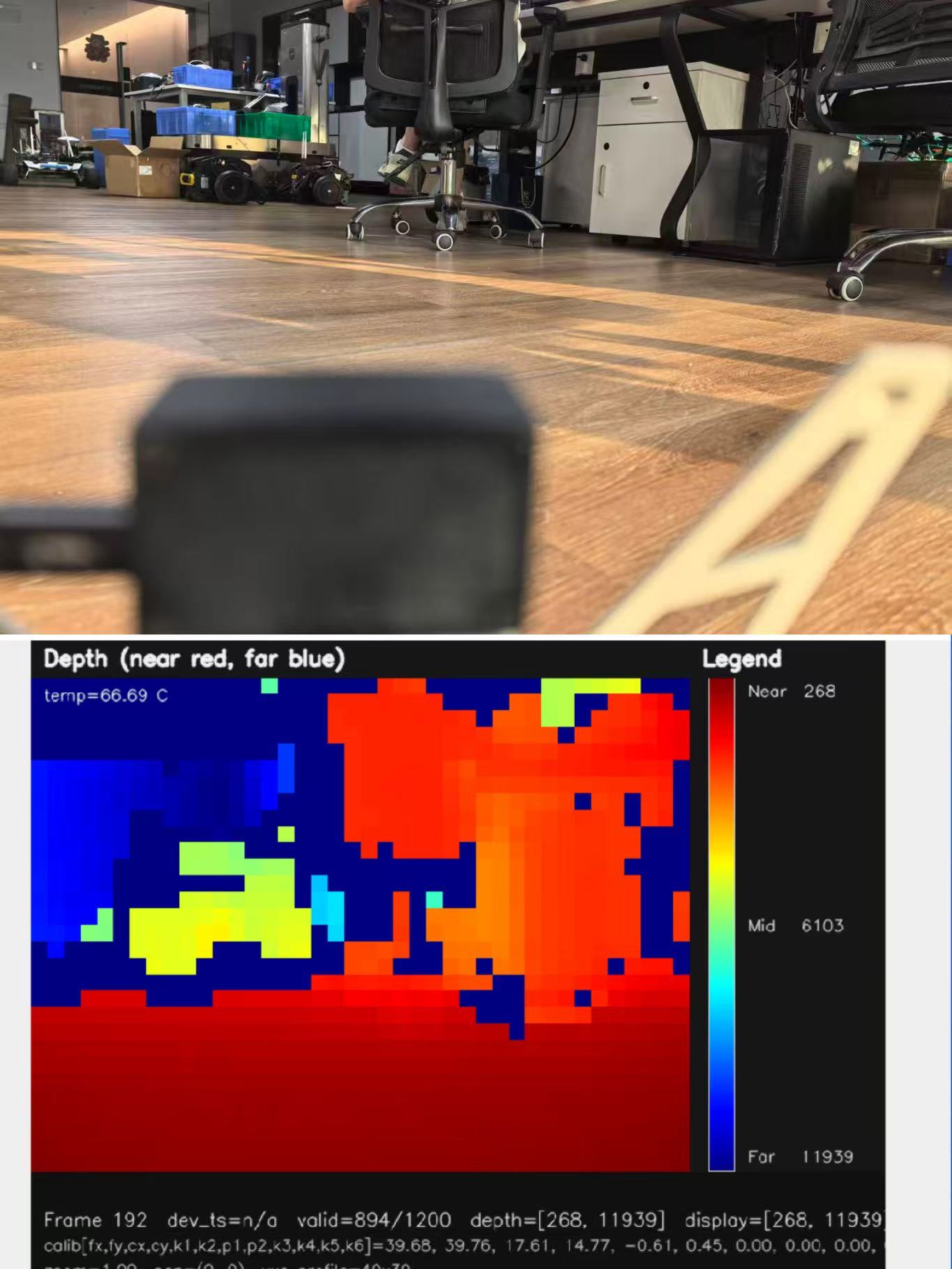
Frequently Asked Questions About UAV LiDAR Sensors
Will the LiDAR sensor maintain reliable range in bright outdoor sunlight?
Is HM-LD1 light and efficient enough for UAV integration?
Can a 40 × 30 LiDAR sensor replace a survey-grade UAV mapping LiDAR?
Is 10 fps fast enough for drone obstacle avoidance?
Can HM-LD1 connect directly to a flight controller?
Does ±3 cm accuracy mean the drone can always hold altitude within 3 cm?
Can more than one HM-LD1 be installed on the same UAV?
What information should be provided when requesting a LiDAR recommendation?
📚 References & Further Reading
- Industry Standard: Innoviz Technologies for broader LiDAR industry context, and Bynav Technology for precision positioning ecosystem context.
- Related Guide: HM-D20 precision RTK module, P100R 3D depth camera, and SpacemiT K3 RISC-V AI CPU.






