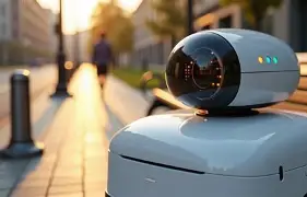
DToF iToF Sensor Guide: How to Choose the Right ToF LiDAR Module for Robots, Drones, and AMRs
3D perception is no longer optional for robots, drones, autonomous mobile robots, inspection platforms, and industrial vision systems. In the shop, this usually shows up as a simple question with a not-so-simple answer: “Which depth sensor should we build around?” Whether you are designing an AMR for warehouse navigation, a UAV for low-altitude inspection, or an embedded device that must detect people and objects, one of the most important sensor decisions is often misunderstood: DToF vs iToF. When comparing dtof itof sensing technologies, the question is not simply which one is “better.” The real question is which one gives your robot, drone, or AMR the right mix of range, sunlight tolerance, frame rate, resolution, field of view, power consumption, and integration flexibility.
Here’s the deal: both DToF and iToF are Time-of-Flight technologies, but they behave differently once you put them on a moving machine in a real warehouse, yard, plant floor, or inspection job. A sensor that looks great on a bench can get noisy when it sees sunlight, black rubber, shiny metal, glass, vibration, dust, or fast motion. This guide explains the engineering difference between Direct Time-of-Flight and Indirect Time-of-Flight, then translates those differences into practical selection criteria for robotics and industrial buyers.
You will learn how DToF and iToF sensors measure distance, where each technology performs best, what mistakes to avoid, and how to evaluate a real module such as the DTOF Solid state LiDAR HM-LD1, a compact SPAD dToF solid-state LiDAR module designed for obstacle avoidance, distance detection, depth mapping, 3D point cloud output, and embedded integration through UART, UDP, or UVC.
Look, the right sensor choice is not about winning a terminology debate. It is about keeping the robot from clipping a pallet, helping a drone hold altitude over rough ground, giving an AMR enough stopping distance, and making sure your software team can actually read and use the depth data without fighting the hardware for weeks.
We’ve recently been testing the HM-LD1 compact dToF LiDAR in a variety of r…
Table of Contents
- 👉 Quick Answer: DToF vs iToF for Robots, Drones, and AMRs
- 👉 What Is Time-of-Flight 3D Sensing?
- 👉 How DToF Sensors Work
- 👉 How iToF Sensors Work
- 👉 DToF vs iToF: Technical Comparison Table
- 👉 How to Choose a ToF Sensor for Robotics and AMRs
- 👉 Choosing DToF or iToF for Drones and UAVs
- 👉 Industrial Use Cases: Obstacle Avoidance, SLAM, Inspection, and Safety
- 👉 Recommended DToF LiDAR Module: HM-LD1
- 👉 Integration Guidelines: Interfaces, SDKs, and Embedded Platforms
- 👉 Common Mistakes When Selecting DToF or iToF Sensors
- 👉 FAQ: DToF, iToF, ToF LiDAR, and Robotics Integration
- 👉 Conclusion: Which ToF Sensor Should You Choose?
Quick Answer: DToF vs iToF for Robots, Drones, and AMRs
Quick answer: For robotics, drones, and AMRs, DToF is usually the better choice when the application requires longer-distance measurement, outdoor performance, obstacle detection, and compact LiDAR-style navigation. iToF is often a better fit for short-range 3D imaging, indoor depth cameras, AR, gesture control, and applications where high pixel resolution at close range matters more than maximum range.
DToF stands for Direct Time-of-Flight. It measures the direct travel time of emitted light pulses as they leave the sensor, reflect from a target, and return to the receiver. iToF stands for Indirect Time-of-Flight. It measures distance by comparing the phase shift between emitted modulated light and the reflected signal received by the sensor.
In practical terms, DToF is often stronger for longer range, outdoor ranging, sunlight-tolerant robotic navigation, distance detection, and UAV altitude or terrain-following use cases. iToF is often strong for short-range depth imaging, smart cameras, gesture recognition, AR, and indoor 3D imaging. For teams evaluating camera-style depth perception, compare this with the 3D Depth Camera P100R. For mobile robots, drones, AMRs, and inspection platforms, DToF is frequently preferred when distance reliability and environmental robustness matter more than high-resolution short-range imaging.
Here’s how I would frame it for an engineering review: if the machine is moving through changing environments and you care about reliable distance readings at several meters, start your evaluation with DToF. If the machine is mostly looking at nearby objects indoors and needs a dense camera-like depth image, iToF deserves a close look.
What Is Time-of-Flight 3D Sensing?
Time-of-Flight Distance Measurement in Simple Terms
Time-of-Flight sensing calculates distance by observing how light behaves after it is emitted toward a target. A light source, typically infrared, sends energy into the scene. The light reflects from objects such as pallets, walls, floors, people, machines, racks, or terrain. A receiver detects the returned signal, and the system converts that signal into distance data.
The exact calculation depends on the ToF method. DToF focuses on the direct travel time of pulses. iToF focuses on phase relationship. In both cases, timing precision is critical because light travels extremely fast. Even a very small timing error can become a meaningful ranging error. This is why emitter quality, receiver sensitivity, optics, calibration, and signal processing are all important.
Look at it this way: the sensor is not guessing distance from appearance. It is measuring a light-based event and converting that measurement into depth. That is why ToF sensors are so useful when a robot needs usable range data, not just a pretty image.
Why ToF Sensors Are Used in Robotics and Industrial Automation
Robotics teams use ToF sensors because they provide direct depth information, not just a flat image. Depth information helps robots estimate how far away an obstacle is, detect nearby people, support docking, maintain distance from a wall, measure object presence, build local maps, and support safety-zone monitoring. In UAVs, ToF distance feedback can help with altitude hold, landing assistance, terrain following, and low-altitude obstacle avoidance.
Industrial automation applications also benefit from ToF depth data. A depth sensor can support volume measurement, object detection, zone intrusion monitoring, smart access control, inspection systems, and machine vision tasks where distance is more important than color texture. For a broader background on LiDAR concepts and ranging systems, see Wikipedia’s LiDAR overview.
ToF vs Camera-Only and Ultrasonic Sensing
Camera-only systems can be powerful, but they often depend on lighting, surface texture, visual features, and algorithmic interpretation. Ultrasonic sensors are simple and inexpensive, but they usually have wide beams, lower spatial resolution, and less useful 3D structure. ToF sensors provide direct depth measurement and can be designed as compact LiDAR-style modules that output depth maps or 3D point cloud data. This makes them valuable when a robot needs distance information in real time rather than only image recognition.
In the shop, ultrasonic sensors are still handy for rough presence detection, and RGB cameras are excellent for classification and scene understanding. But when you need a machine to know that an object is 1.2 meters away, 3.7 meters away, or inside a stop zone right now, ToF depth sensing can save a lot of engineering pain.
How DToF Sensors Work
Direct Time Measurement of Light Pulses
DToF sensors emit short light pulses, often using infrared laser or VCSEL illumination, and measure the time between pulse emission and photon return. The basic distance formula is: distance equals the speed of light multiplied by time-of-flight, divided by two. The division by two is necessary because the light travels from the sensor to the object and then back to the receiver.
This direct timing method is why DToF is attractive for ranging tasks. Instead of estimating distance from image scale or visual appearance, the sensor measures a physical travel-time event. In robotics, this can provide robust information for determining whether an obstacle is close enough to require slowing, stopping, steering, or triggering a warning zone.
Here’s the deal with DToF: it is fundamentally built around timing. That makes it a natural fit for distance measurement, especially when the job is less about recognizing a detailed object shape and more about knowing where solid surfaces are in front of the machine.
SPAD-Based DToF and Photon Detection
Many modern compact DToF modules use SPAD technology. SPAD means Single-Photon Avalanche Diode. SPAD receivers are sensitive enough to detect very weak returned light signals, which is useful when the target is distant, dark, angled, or only partially reflective. SPAD arrays can support solid-state LiDAR architectures because they allow photon detection without requiring a large rotating scanner.
In SPAD-based DToF systems, signal processing often uses statistical methods such as histogram processing to estimate the most likely target distance from the returned photons. This helps separate useful reflections from noise and ambient light. Companies such as ams OSRAM are part of the broader optical sensing and illumination ecosystem used in modern ToF and LiDAR applications.
That photon-level sensitivity is a big reason compact DToF modules have become interesting for mobile platforms. You can get useful depth information from a small package, provided the module has the right optics, emitter design, filtering, firmware, and data interface for the job.
Strengths of DToF for Robotics
DToF is often selected for robotics because it can be effective for medium-to-longer-range obstacle detection, outdoor distance measurement, and LiDAR-style perception in compact platforms. A DToF module can help AMRs detect objects in front of the vehicle, support UAV altitude feedback, assist terrain following, and provide depth information for industrial inspection. Depending on module design, DToF can output point cloud data, depth images, or simplified distance zones.
DToF is also attractive where sunlight tolerance matters. Outdoor robots and drones must operate under changing ambient light conditions, including direct sun, reflections from concrete or metal, and shadows. A well-designed DToF sensor can maintain practical ranging in these environments, although actual performance still depends on optical design, emitter power, receiver sensitivity, filtering, and target reflectivity.
For engineering teams, the big DToF advantages usually come down to these field-level benefits:
✅ Better fit for medium- and longer-range robotic distance measurement than many short-range depth camera approaches.
✅ Stronger candidate for outdoor robots, drones, and inspection platforms that need usable readings in high ambient light.
✅ Compact solid-state options that avoid rotating towers and reduce mechanical complexity.
✅ Useful output formats such as depth maps and 3D point clouds, depending on the module.
✅ Good match for obstacle avoidance, approach control, altitude assistance, zone monitoring, and embedded 3D sensing.
Limitations of DToF
DToF is not automatically superior in every category. Some iToF depth cameras may offer higher camera-like pixel resolution at close range. DToF optical design and timing electronics can also be demanding. Multi-path reflections, highly reflective surfaces, low-reflectivity materials, and environmental contamination can still affect measurement quality. Engineers must match field of view, resolution, frame rate, and interface to the actual perception stack instead of assuming that the DToF label alone guarantees success.
Look, no sensor is magic. A DToF module still needs a clean optical window, stable power, solid mounting, proper calibration, and realistic software thresholds. If your robot is driving through dust, steam, glare, rain, or polished metal environments, you need to test those conditions instead of trusting a single maximum-range number.
How iToF Sensors Work
Phase-Shift Distance Measurement
iToF sensors use modulated light rather than measuring each pulse’s direct return time. The emitter sends out light with a known modulation pattern. When the light reflects from a target and returns to the sensor, the system compares the phase of the received signal with the phase of the emitted signal. That phase shift is converted into distance.
This method is common in 3D cameras and short-range depth sensors. Because iToF can be implemented in camera-like sensor formats, it is often used where the system needs a dense depth image for close-range interaction, object segmentation, user presence detection, or indoor vision.
In plain terms, iToF behaves more like a depth camera. That is not a bad thing. It can be exactly what you want when the scene is nearby, controlled, and image-like depth detail matters.
Strengths of iToF Sensors
iToF is often strong in short-range depth imaging. It can be compact, cost-effective in high-volume applications, and useful for camera-style 3D depth maps. Common applications include AR and VR, gesture control, face detection, smart cameras, indoor robotics, object recognition, and machine vision tasks where the required range is relatively short and the lighting environment is controlled.
If an application needs to understand the shape of a nearby hand, face, package, or small object, iToF may be a strong candidate. The higher depth image resolution available in some iToF modules can help with segmentation and close-range recognition tasks.
For close-range applications, iToF has several practical advantages:
✅ Good fit for indoor 3D depth cameras and camera-like perception systems.
✅ Useful for gesture recognition, AR, smart cameras, people detection, and short-range machine vision.
✅ Often available in compact modules with higher pixel resolution for nearby scenes.
✅ Strong choice when image-like depth detail matters more than long-distance ranging.
Limitations of iToF for Mobile Robots and Outdoor Systems
iToF can experience range ambiguity because phase measurement repeats over distance, a phenomenon often described as phase wrapping. Outdoor sunlight can reduce signal-to-noise ratio, and multi-path interference can distort distance readings when light reflects from multiple surfaces before returning to the sensor. These issues do not make iToF unsuitable in every robot, but they must be evaluated carefully for mobile robots, AMRs, and UAVs that operate in variable lighting and require reliable obstacle detection at several meters or more.
In the shop, this is where teams get into trouble. They pick a high-resolution short-range depth camera, mount it on a mobile robot, then discover that the useful range collapses under sunlight or the depth output gets unreliable on shiny industrial surfaces. That does not mean iToF is poor technology. It means it was probably selected for the wrong job.
DToF vs iToF: Technical Comparison Table
“DToF vs iToF” is not a one-dimensional comparison. A better selection process weighs range, frame rate, resolution, field of view, sunlight tolerance, power budget, mechanical size, software access, output data format, and target environment. The table below summarizes the most important differences for robotics, drones, AMRs, embedded vision, and industrial automation.
| Selection Factor | DToF Sensor | iToF Sensor | Best Fit |
|---|---|---|---|
| Measurement Principle | Measures direct return time of light pulses | Measures phase shift of modulated light | DToF for direct ranging; iToF for phase-based depth imaging |
| Typical Range | Often stronger for medium to longer range | Often optimized for short to medium range | DToF for obstacle detection and navigation |
| Outdoor Performance | Generally better sunlight tolerance when properly designed | Can be more sensitive to ambient light | DToF for drones, AMRs, and outdoor inspection |
| Depth Image Resolution | Can be lower depending on module architecture | Often available in higher camera-like pixel resolutions | iToF for close-range 3D imaging |
| Robotics Navigation | Strong fit for ranging, obstacle avoidance, and compact LiDAR perception | Useful for close-range perception and object detection | DToF for navigation-critical use cases |
| Power and Size | Can be compact and efficient depending on design | Also compact, especially in camera modules | Application-dependent |
| Common Applications | Robots, drones, AMRs, industrial distance detection, safety zones | AR, gesture recognition, smart cameras, indoor 3D vision | Choose based on operating distance and environment |
For a wider discussion of LiDAR selection in robotics and drones, see our guide to LiDAR 3D scanners for robotics, drones, and industrial vision.
That table is a good starting point, but do not treat it like a purchasing checklist by itself. The final call should come from testing the actual sensor on the actual platform. Put it at the intended mounting height. Aim it through the actual protective window. Run it in the actual lighting. Test the actual floor, pallet, wall, black plastic, stainless steel, cardboard, and human-leg cases your robot will see.
How to Choose a ToF Sensor for Robotics and AMRs
1. Start With the Required Detection Range
Begin by calculating how far ahead the robot must detect obstacles. An indoor AMR moving slowly in a controlled aisle may need reliable detection over a few meters, while a faster platform may require 10 meters or more to allow braking and path replanning. Docking applications may need short-range accuracy, while warehouse aisle navigation may need medium-range perception. Outdoor robots need stronger sunlight performance and must be tested against target materials with different reflectivity.
Here’s the practical method: work backward from vehicle speed and stopping distance. If the robot cannot stop safely after the sensor first sees an obstacle, the sensor range is not enough. That includes compute latency, frame rate, filtering delay, motor response, tire traction, payload mass, and worst-case floor conditions.
2. Match Field of View to Robot Geometry
Field of view determines what part of the scene the sensor can observe. A wider FOV helps detect obstacles near the front corners of a robot, while a narrower FOV may support longer-distance targeting but can miss side obstacles. Sensor height, tilt angle, mounting position, and blind zones matter. Low-profile robots may need multiple modules to cover the front, sides, and low obstacles. Engineers should model the sensor’s viewing volume against the robot’s footprint and expected obstacle types.
In the shop, field of view mistakes are common. A sensor may have enough range on paper, but if it is mounted too high, tilted poorly, or blocked by the robot housing, it may miss low obstacles, ramps, forks, feet, cables, and pallet edges. FOV is not just a spec-sheet number. It is a geometry problem.
3. Evaluate Point Cloud and Depth Map Output
A simple distance value may be enough for presence detection, but complex robots often need richer data. Depth maps are useful for vision algorithms because they present distance as a two-dimensional array. Point cloud output is useful for 3D clustering, obstacle classification, local mapping, and terrain analysis. For AMR navigation, a 3D point cloud can be converted into occupancy grids, height maps, or obstacle zones. SDK access and data format documentation can reduce integration time significantly.
Ask your software team what they actually want to consume. Some teams need raw depth frames. Some want point clouds. Some want a filtered zone output. Others want confidence data, timestamps, calibration parameters, or access to frame metadata. The earlier you confirm the output format, the less time you waste writing glue code later.
4. Check Interfaces and Embedded Compatibility
Interface selection affects system architecture. UART is useful for microcontrollers, flight controllers, and low-bandwidth ranging packets. UDP is useful for networked robot computers and multi-sensor systems. UVC is attractive for PCs, Linux systems, and Raspberry Pi-style development because it can behave like a video-class device. For industrial deployment, also check whether the supplier supports Windows, Linux, and ARM Linux SDKs, because many robot controllers are based on embedded Linux platforms.
For a clean integration review, check these interface items early:
⚙️ Required bandwidth for depth maps, point clouds, or zone data.
⚙️ Timestamp behavior and synchronization with other sensors.
⚙️ Driver support for the final processor, not just a Windows demo laptop.
⚙️ Cable length, connector reliability, and EMI exposure in the robot body.
⚙️ Error handling when packets drop, frames freeze, or the sensor reboots.
5. Consider Mechanical Integration
Mechanical integration should include module dimensions, weight, mounting method, heat dissipation, cable routing, vibration exposure, lens protection, and environmental sealing. Robots and UAVs are not lab benches. They encounter shock, dust, thermal changes, sunlight, cleaning processes, and mechanical stress. A compact solid-state module can simplify packaging, but it still needs a clean optical window and stable mounting alignment.
Do not leave the mechanical package until the end. A beautiful sensor can perform poorly if it is hidden behind tinted plastic, exposed to dust buildup, mounted near vibration sources, or thermally trapped inside a sealed enclosure. Optical windows need the right material, cleanliness, angle, and anti-reflection behavior. Mechanical design affects sensing performance more than many teams expect.
6. Validate Accuracy Where It Matters
Accuracy should be judged at the distances that matter to the application. A docking robot may care most about readings under one meter. A drone may care about altitude readings from two to eight meters. An AMR may care about reliable detection at stopping distance. Do not only check the best-case accuracy printed on a data sheet. Measure repeatability, noise, missed pixels, and drift across real targets.
For industrial use, test bright targets, dark targets, angled surfaces, shrink wrap, black rubber, reflective tape, stainless steel, concrete, cardboard, painted metal, people, and anything else the robot may encounter. If the machine will operate near sunlight, open dock doors, forklifts, dust, or welding glare, include those conditions in the test plan.
Choosing DToF or iToF for Drones and UAVs
Altitude Hold and Terrain Following
Drones need fast and reliable distance feedback, especially during takeoff, landing, low-altitude flight, and operation near uneven terrain. A downward-facing ToF sensor can support altitude hold by measuring distance to the ground. Terrain following requires stable readings over grass, concrete, soil, metal, and other surfaces with different reflectivity. DToF is often attractive in UAV applications when outdoor range and sunlight tolerance are important.
Here’s the deal with UAVs: the sensor does not get a quiet life. It sees vibration, prop wash, changing sun angle, fast altitude transitions, and ground surfaces that do not reflect light the same way. A bench test over a white board is not enough. Test over grass, asphalt, concrete, gravel, painted floors, and dark soil if those surfaces matter to the mission.
Obstacle Avoidance for Low-Altitude Flight
Forward, downward, or side-facing modules can help detect obstacles during low-altitude flight. The correct FOV depends on flight speed, braking distance, and expected obstacle geometry. A wide FOV improves coverage but may reduce angular detail. A higher frame rate can improve reaction time, but the control system must also process the data quickly. Sensor fusion with IMU, optical flow, cameras, radar, or other distance sensors can improve reliability.
For drone obstacle avoidance, you need to think like a controls engineer. The sensor has to see the obstacle early enough, report it fast enough, and provide data the flight controller can use without delay. If the aircraft is moving quickly, a slow depth stream may be too late even if the range number looks good.
Payload Weight and Power Budget
Every gram affects flight time, and every watt affects battery endurance. This is why compact solid-state modules are useful for UAV development. A non-rotating module reduces mechanical complexity and can be easier to mount in a small airframe. Later in this guide, the HM-LD1 is presented as a 28 g, 1.2 W DToF LiDAR module suitable for space- and weight-constrained robotic and UAV development.
When selecting a ToF sensor for UAV work, keep the short list practical:
✅ Low mass so the aircraft keeps reasonable flight time.
✅ Low power draw so the sensor does not punish the battery budget.
✅ Outdoor ranging capability under strong ambient light.
✅ Stable output during vibration and fast movement.
✅ Interface compatibility with the flight controller or onboard computer.
Industrial Use Cases: Obstacle Avoidance, SLAM, Inspection, and Safety
AMR and Mobile Robot Obstacle Avoidance
AMRs must detect pallets, racks, human legs, cables, ramps, low objects, boxes, and unexpected debris. A compact DToF module can act as an additional perception layer that complements 2D LiDAR, cameras, bumpers, ultrasonic sensors, and safety-rated devices. It can help identify objects that may be missed by a single planar scanner, especially when height information matters.
Look, one flat scan plane does not always tell the whole story. A pallet fork, overhanging load, low black object, or cable on the floor can sit outside the best part of a single sensor’s coverage. Depth sensing gives the robot another way to understand what is actually in front of it.
SLAM and Environmental Perception
DToF point clouds can support mapping and local perception, but the quality of SLAM depends on range, resolution, FOV, frame rate, mounting position, and algorithm design. Many practical robots combine depth sensing with IMU data, wheel odometry, cameras, or 2D LiDAR. For readers comparing broader scanning architectures, see our LiDAR scanner guide.
For SLAM, be careful with expectations. A compact fixed-FOV DToF module may be excellent for local obstacle detection and 3D perception, but full 360-degree map building may require multiple sensors, a rotating scanner, or sensor fusion. The right architecture depends on whether you need local safety awareness, navigation support, full mapping, or object-level perception.
Industrial Inspection and Hard-to-Reach Structures
Industrial inspection often requires distance measurement to objects that are difficult or unsafe for people to approach. The HM-LD1 product description highlights usefulness for measuring distances to structures such as bridges, expressways, and dams. It also describes outdoor measurement up to 8 meters in clear summer day conditions assuming 80,000 lux. For inspection robots and UAVs, this kind of compact ranging can support standoff distance control, object approach, and structural measurement workflows.
In inspection work, standoff distance matters. If a drone is inspecting a bridge, dam, pipe rack, tank, tunnel wall, or overhead structure, keeping a controlled distance can improve image quality and reduce collision risk. A compact DToF sensor can become part of that distance-control loop.
Zone Intrusion and Smart Security
Depth sensing is also valuable for zone intrusion monitoring, human presence detection, object recognition support, volume measurement, and smart security. Compared with RGB video, depth-based detection can be more privacy-friendly because it can identify shape, distance, and occupancy without relying on detailed facial or color imagery. This makes ToF sensing useful for smart buildings, restricted zones, industrial safety monitoring, and access-control systems.
For industrial zone monitoring, depth can be cleaner than relying on appearance alone. A system can detect that something entered a volume of space, crossed a distance threshold, or occupied a restricted area. That is useful in warehouses, loading docks, automated cells, entrances, and smart security installations.
Recommended DToF LiDAR Module: HM-LD1
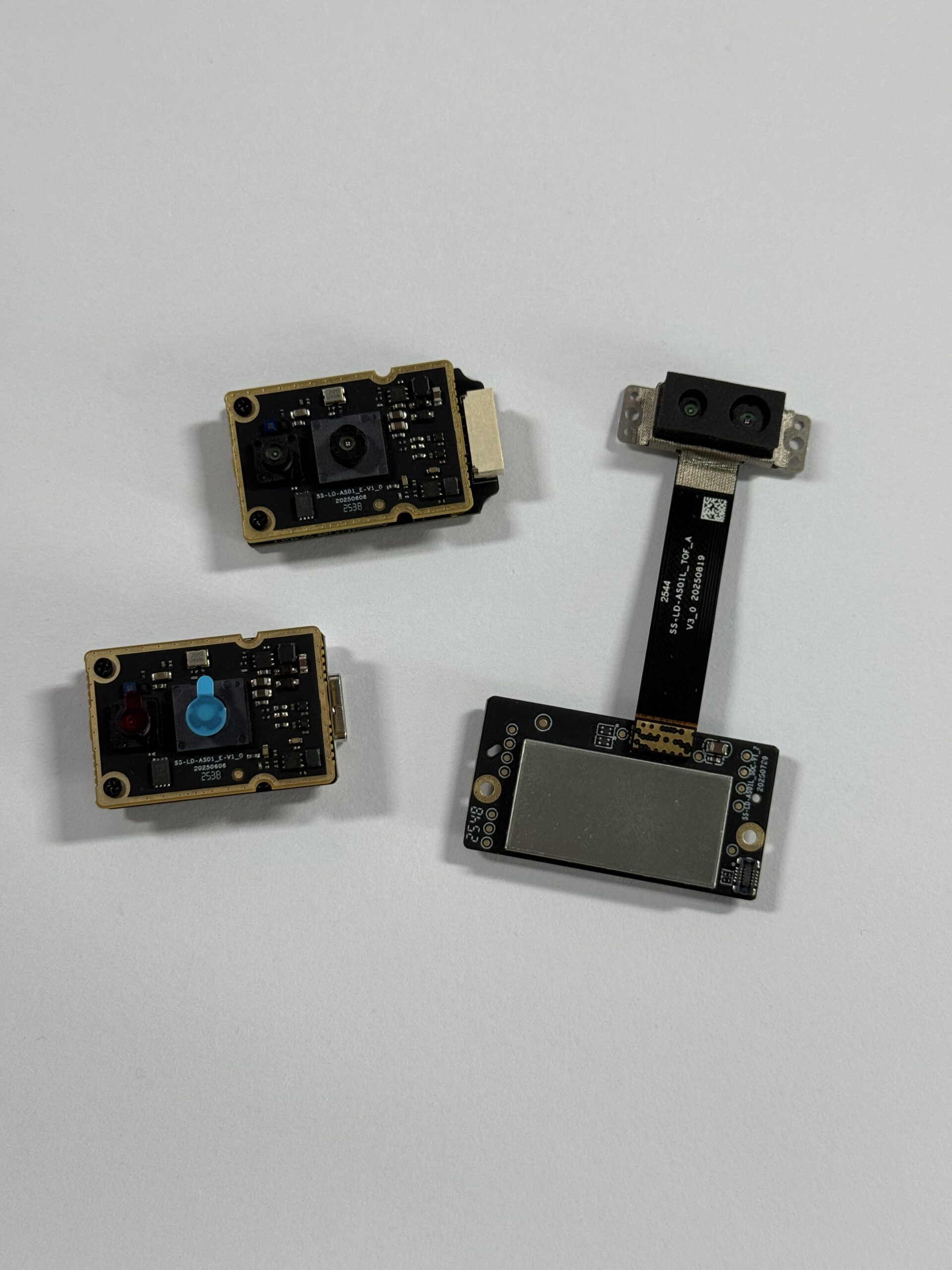
After understanding the DToF vs iToF tradeoff, engineers still need to evaluate real modules by range, accuracy, field of view, resolution, frame rate, interfaces, software support, power, size, and weight. The DTOF Solid state LiDAR HM-LD1 is a compact solid-state LiDAR module based on SPAD dToF technology for robots, drones, cameras, AMRs, inspection systems, security systems, and embedded vision platforms. It delivers real-time depth images and 3D point cloud data for accurate environmental perception.
View product page: DTOF Solid state LiDAR HM-LD1
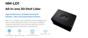
View Product Details & Pricing ➔
| DTOF Solid State LiDAR HM-LD1 Specifications | |
|---|---|
| Product Name | DTOF Solid state LiDAR HM-LD1 |
| Technology | SPAD dToF solid-state LiDAR |
| Dimension | 43.5 mm × 30 mm × 26.5 mm |
| Ranging Capability | Indoor: 0.5–25 m; Outdoor: 0.2–8 m |
| Ranging Accuracy | ±3 cm |
| Field of View | 60° horizontal × 45° vertical |
| Resolution | 40 × 30 |
| Frame Rate | 10 fps |
| Interface | UART / UDP / UVC |
| Operating Temperature | -20 ℃ to 60 ℃ |
| Power Consumption | 1.2 W |
| Weight | 28 g |
| Development Support | SDKs for x86 Windows, x86 Linux, and ARM Linux |
| Output Data | Real-time depth images and 3D point cloud data |
| Product URL | https://myrobotproject.com/product/dtof-solid-state-lidar-hm-ld1/ |
Why HM-LD1 Fits Robotics and UAV Development
The HM-LD1 fits many robotics and UAV development projects because it combines compact mechanical packaging with practical 3D sensing output. Its solid-state LiDAR architecture means there is no rotating mechanical tower, which can reduce size, weight, and mechanical vulnerability. At 28 g and 1.2 W, it is suitable for battery-powered systems where payload mass and energy consumption are important.
The 60° horizontal × 45° vertical FOV gives practical coverage for obstacle detection and depth perception. The 40 × 30 resolution is suitable for distance maps, zone detection, obstacle presence, lightweight point cloud processing, and embedded perception tasks where every pixel must be processed efficiently. The ±3 cm ranging accuracy supports practical robot distance tasks such as obstacle approach, docking assistance, altitude estimation, inspection standoff control, and local environment sensing.
HM-LD1 supports indoor ranging from 0.5 to 25 m and outdoor ranging from 0.2 to 8 m. According to the product description, it can perform outdoor measurement up to 8 meters on a clear summer day under assumed 80,000 lux conditions. This makes it relevant for drones, AMRs, inspection robots, smart cameras, security systems, and robotics developers who need depth images and 3D point cloud data in a compact package.
Here’s what stands out from an integration standpoint: the module is small enough to package into compact robots, light enough for UAV payload budgets, and flexible enough to connect through UART, UDP, or UVC depending on the controller architecture. That combination matters because many robotics teams start on a desktop, move to embedded Linux, and then need stable deployment on production hardware.
For a mobile robot or AMR, the 60° × 45° field of view can be used for forward obstacle detection, local depth mapping, approach monitoring, or supplementary 3D perception. For a drone, the same type of module can be evaluated for downward distance measurement, low-altitude terrain following, or structural standoff control. For industrial security or smart sensing, depth output can support zone occupancy, object presence, and intrusion monitoring.
Brochure Download CTA
Download the product brochure: DTOF SSL HM-LD1 Product Brochure
Integration Guidelines: Interfaces, SDKs, and Embedded Platforms
UART Integration
UART is useful for embedded controllers, microcontrollers, flight controllers, and low-bandwidth use cases. If the robot only needs simplified distance packets, zone information, or basic ranging status, UART can be straightforward and robust. It is often selected when the sensor is connected directly to an embedded control board rather than a high-performance vision computer.
UART is not the right choice for every high-bandwidth depth stream, but it is hard to beat for simple embedded control. If your controller only needs “obstacle detected,” “nearest distance,” or a small set of zone readings, UART can keep the system simple and predictable.
UDP Integration
UDP is suitable for networked robot compute systems. It can be useful when transmitting point cloud or depth data to a robot controller, perception computer, or distributed sensor network. For AMRs and industrial robots with Ethernet-based architectures, UDP can simplify multi-sensor layouts and allow the perception system to receive data from several modules.
With UDP, the engineering focus shifts to packet handling, timestamps, network load, and loss tolerance. In a clean lab network, everything may look easy. On a full robot with multiple cameras, LiDAR, motor drives, Wi-Fi, logs, and diagnostics, bandwidth planning becomes part of the job.
UVC Integration
UVC is useful for PCs, Linux systems, Raspberry Pi-style development, and camera pipelines. Because UVC devices can behave like video-class devices, they can simplify prototyping and testing. Developers can often visualize depth streams more quickly and connect the module to existing image-processing workflows.
For prototypes, UVC can be a real time-saver. If the development team can plug in a module, view frames, log data, and test filters without writing a custom low-level driver first, the project moves faster. Just make sure the final embedded platform supports the same path reliably.
SDK and Platform Support
HM-LD1 supports SDKs for x86 Windows, x86 Linux, and ARM Linux. This matters because many robotics teams prototype on a PC and later deploy on embedded Linux hardware. SDK documentation, demos, and sample code reduce integration risk, especially when teams need to parse depth maps, generate point clouds, calibrate coordinate frames, and test performance across platforms.
In a real product program, SDK support can be just as important as sensor optics. A module with poor documentation can burn weeks of development time. Before committing to a sensor, verify sample code, frame formats, coordinate conventions, calibration behavior, firmware update process, and support contacts.
Data Processing: Depth Map vs Point Cloud
A depth map is a two-dimensional array of distance values, while a point cloud represents 3D coordinates. Robotics pipelines may apply filtering, confidence thresholds, ground removal, clustering, voxelization, and occupancy-grid conversion. Sensor fusion with IMU, wheel odometry, cameras, 2D LiDAR, or other sensors improves robustness, especially in dynamic industrial environments.
A practical processing stack often includes these steps:
⚙️ Read the sensor stream through UART, UDP, UVC, or the SDK.
⚙️ Validate frame timing, dropped packets, and frame consistency.
⚙️ Apply confidence thresholds and remove invalid or unstable measurements.
⚙️ Convert depth maps into point clouds when 3D geometry is needed.
⚙️ Transform sensor coordinates into the robot coordinate frame.
⚙️ Filter ground, walls, or known robot body reflections.
⚙️ Build obstacle zones, height maps, clusters, or occupancy grids.
⚙️ Fuse with odometry, IMU, camera, 2D LiDAR, or other perception sources.
Mounting, Calibration, and Coordinate Frames
Mounting location is not just a mechanical decision. It defines what the sensor can see and how useful the data will be. A front-mounted module may support obstacle avoidance. A downward-facing module may support altitude or floor detection. A side-mounted module may help wall following or docking. Once the module is mounted, the robot software needs the correct transform from the sensor coordinate frame to the robot base frame.
Small alignment errors can create real perception problems. If a depth module is tilted a few degrees differently than the software assumes, ground points may appear as obstacles or obstacles may be projected into the wrong location. Calibration should be treated as part of the integration process, not something to guess by eye.
Common Mistakes When Selecting DToF or iToF Sensors
Mistake 1: Choosing Only by Maximum Range
Maximum range alone does not guarantee reliable detection. Target reflectivity, sunlight, target size, field of view, integration time, optical window quality, and algorithm thresholds all affect real performance. Engineers should test the actual objects the robot will encounter, not only ideal lab targets.
A maximum range number is usually measured under specific conditions. Your robot may see black plastic, dirty concrete, glossy shrink wrap, people wearing dark clothing, pallet edges, glass, steel, or angled surfaces. Those are the targets that matter.
Mistake 2: Ignoring Outdoor Ambient Light
Sunlight can reduce signal quality and cause missed or noisy depth readings. Outdoor robots should be tested in high-lux environments, direct sun, shadows, and mixed reflective conditions. DToF modules designed for outdoor ranging are often better suited, but every module still needs field validation.
Open dock doors can create sunlight problems even for indoor AMRs. A robot may run fine in an aisle, then lose depth stability near a loading bay. If the operating site includes strong light transitions, include them in validation.
Mistake 3: Confusing Depth Resolution With Navigation Quality
Higher resolution is useful, but it is not always required for navigation. For obstacle avoidance, reliable distance zones may matter more than high pixel count. For object recognition or shape analysis, higher resolution may be beneficial. The right choice depends on the perception algorithm and required reaction behavior.
Look, more pixels are not automatically better if the robot cannot process them fast enough or if the depth data is unstable at the required range. For many AMR tasks, clean and reliable distance data beats a high-resolution stream that collapses under real conditions.
Mistake 4: Forgetting Software and Interface Support
Good hardware can fail at the system level if data access is difficult. SDKs, documentation, sample code, and OS compatibility matter. Support for Windows, Linux, and ARM Linux is valuable because industrial teams often move from desktop development to embedded deployment.
Before buying a stack of modules, ask whether your team can log data, replay data, update firmware, parse frames, access confidence information, and debug failures. A sensor without usable software support can become the slowest part of the project.
Mistake 5: Treating ToF as a Single-Sensor Safety Solution
Safety-critical robotics usually requires redundancy and compliance with appropriate safety standards. ToF sensors can support perception and obstacle detection, but industrial safety systems may also require bumpers, safety-rated LiDAR, emergency stops, cameras, IMU, wheel odometry, and validated control logic. Use sensor fusion and formal risk assessment where human safety is involved.
This point matters. A ToF module can be very useful for perception, but do not casually promote a non-safety-rated sensor into the only protective device around people. For human safety, follow the applicable standards, risk assessment process, and validation requirements.
Mistake 6: Ignoring the Protective Window
Many teams test a bare sensor on the bench, then place it behind a protective window in the final enclosure. That window can change performance. Material, thickness, tint, angle, surface coating, dust, scratches, condensation, and internal reflections all affect optical sensors. If the final robot has a front cover or lens window, test the sensor through that exact window.
Mistake 7: Forgetting Maintenance Conditions
Industrial robots get dirty. Dust, oil mist, water spots, fingerprints, cleaning chemicals, and abrasion can reduce optical performance. Maintenance planning should include how the optical window is cleaned, how contamination is detected, and what the robot does when sensor confidence drops.
FAQ: DToF, iToF, ToF LiDAR, and Robotics Integration
What is the real difference between DToF and iToF, and why does it matter for robotics?
Can a DToF sensor replace a traditional LiDAR tower on robot vacuums or mobile robots?
If a DToF sensor shows malfunction, missing depth data, or point cloud occlusion, can it be fixed by software?
Is DToF better than iToF for outdoor robots?
What specifications matter most when selecting a DToF LiDAR module?
Can DToF LiDAR be used for SLAM?
What is the advantage of a solid-state DToF LiDAR module?
How should engineers test DToF and iToF sensors before production deployment?
Conclusion: Which ToF Sensor Should You Choose?
The best choice between DToF and iToF depends on the application. DToF is generally better for robotics, drones, AMRs, and industrial systems that require longer range, sunlight tolerance, reliable obstacle detection, compact LiDAR-style perception, and practical outdoor ranging. iToF remains valuable for short-range, camera-like 3D imaging and indoor vision tasks such as gesture control, AR, smart cameras, and close-range object detection.
For engineering teams, the right selection process should begin with real operating requirements: detection distance, target type, ambient light, robot speed, FOV, mounting position, frame rate, output data, software access, and embedded platform compatibility. Technology labels help narrow the field, but production decisions should be based on measured performance in the final environment.
Here’s the deal in one sentence: choose DToF when the machine needs dependable distance sensing for motion, navigation, obstacle avoidance, outdoor work, or compact LiDAR-style perception; choose iToF when the machine needs dense short-range depth imaging in a more controlled environment.
If your project requires a compact DToF LiDAR module for robotics, drones, AMRs, obstacle avoidance, depth mapping, or embedded 3D sensing, review the DTOF Solid state LiDAR HM-LD1. Its 0.5–25 m indoor ranging, 0.2–8 m outdoor ranging, ±3 cm accuracy, 60° × 45° FOV, UART/UDP/UVC interfaces, and SDK support for Windows, Linux, and ARM Linux make it a strong candidate for industrial development and deployment.
And before you lock the design, run the sensor on the real machine. Put it through vibration, sunlight, low-reflectivity targets, reflective targets, dirty windows, long cables, embedded drivers, and the actual perception software. That is where good sensor selection turns into a reliable robot.
📚 References & Further Reading
- Industry Standard: AMS Osram and Wikipedia’s LiDAR overview
- Related Guide: LiDAR 3D scanners for robotics, drones, and industrial vision and LiDAR scanner guide