


LiDAR UAV Guide 2026: How to Choose the Right Drone LiDAR Sensor for Mapping, Surveying, and Autonomy
A LiDAR UAV can turn a drone from a flying camera into a real 3D data-collection platform. With the right sensor, a UAV can measure terrain, structures, vegetation, obstacles, industrial assets, and work zones with a level of speed and consistency that is hard to match from the ground. Here’s the deal, though: not every drone LiDAR sensor is built for the same job. A survey-grade mapping payload, a compact obstacle-avoidance LiDAR, and a solid-state dToF depth module may all get called “UAV LiDAR,” but in the field they behave like very different tools.
Look, choosing the wrong system is not just a small purchasing mistake. It can mean weak point clouds, unreliable outdoor detection, short flight time, ugly integration work, or paying for capabilities your drone project does not actually need. In the shop, I always tell teams to start with the mission first, then work backward into the sensor. The sensor spec sheet matters, but the mission decides which specs matter most.
This 2026 guide walks through how to evaluate a LiDAR UAV system from the ground up: measurement principle, range, accuracy, field of view, frame rate, payload weight, power, data interface, GNSS/INS requirements, software workflow, and environmental limitations. It also explains where compact modules such as the DTOF Solid State LiDAR HM-LD1 fit into UAV autonomy, obstacle avoidance, altitude sensing, terrain following, smart inspection, and robotics development.
If your team is trying to build a professional mapping workflow, you need to think about the full UAV LiDAR stack, not just the sensor head. If you are building a compact autonomous drone or robotics prototype, you may care more about weight, power, SDK support, and real-time depth output than formal georeferenced survey accuracy. Those are two different buying decisions, and mixing them up is where a lot of projects get expensive fast.
Table of Contents
- 👉 What Is a LiDAR UAV?
- 👉 How LiDAR UAV Systems Work
- 👉 LiDAR UAV vs Photogrammetry: Which Is Better?
- 👉 Main Applications of UAV LiDAR
- 👉 Types of Drone LiDAR Sensors
- 👉 Key Specs to Compare Before Buying a LiDAR UAV Sensor
- 👉 Choosing LiDAR for Mapping, Surveying, Inspection, and Autonomy
- 👉 UAV LiDAR Integration Workflow
- 👉 Featured Product: DTOF Solid State LiDAR HM-LD1
- 👉 LiDAR UAV Selection Checklist
- 👉 Common Mistakes When Choosing a LiDAR UAV Sensor
- 👉 Final Thoughts: Match the LiDAR UAV Sensor to the Mission
- 👉 FAQ: LiDAR UAV Buying and Integration Question
What Is a LiDAR UAV?
A LiDAR UAV is an unmanned aerial vehicle equipped with a Light Detection and Ranging sensor. The sensor emits light pulses or modulated light, receives reflected signals, and converts those returns into distance values, depth maps, or 3D point clouds. Mounted on a drone, LiDAR lets a team measure places that may be unsafe, slow, or expensive to reach on foot.
The phrase “LiDAR UAV” can mean several things. It may describe a survey-grade drone LiDAR payload used for topographic mapping, a lightweight LiDAR sensor used for collision avoidance, a solid-state depth module used in robotics development, or an inspection system for bridges, expressways, dams, roads, industrial plants, and confined areas. That distinction matters. The best sensor for legal land surveying is not automatically the best sensor for obstacle detection, altitude hold, or autonomous navigation research.
Why LiDAR Is Used on Drones
LiDAR is used on drones because it gives fast 3D measurement from the air. Instead of depending only on images, color, and texture, LiDAR directly measures distance to surfaces. That makes it valuable in complex terrain, low-texture areas, industrial facilities, vegetation, and jobs where ground access is limited or risky. A drone can fly over or near a site and collect geometry quickly, which reduces inspection time and keeps people away from hazardous locations.
For industrial users, a LiDAR UAV can support terrain modeling, asset inspection, corridor mapping, volume measurement, structure monitoring, obstacle detection, and autonomy. For robotics engineers, LiDAR data can become an input for perception algorithms, navigation stacks, SLAM pipelines, or collision-avoidance logic. The value is not just the LiDAR sensor. The value comes from the whole package: sensor output, aircraft stability, positioning, compute, software, power design, and mission planning.
Mapping LiDAR vs Autonomy LiDAR
| Category | Main Goal | Typical Requirements |
|---|---|---|
| Mapping / Surveying LiDAR | Accurate georeferenced point clouds | GNSS/INS, calibration, long range, high point density, post-processing workflow |
| Autonomy / Obstacle Avoidance LiDAR | Real-time perception | Low latency, compact size, low power, reliable interface, predictable detection zones |
| Development / Prototyping LiDAR | Testing algorithms and platforms | SDKs, open interfaces, easy visualization, embedded compatibility |
Survey-grade UAV LiDAR typically requires accurate position and orientation data, usually from GNSS/INS hardware. Autonomy-focused LiDAR may not need global coordinates at all. It may only need reliable local distance data so the drone knows what is nearby. For readers comparing positioning components, see our guide on RTK receptor vs receiver and our technical explanation of multi-band RTK GNSS.
How LiDAR UAV Systems Work
A complete LiDAR UAV system includes more than a light-based range sensor. Depending on the job, it may include the aircraft, LiDAR module, onboard processor, flight controller, GNSS receiver, inertial measurement unit, storage device, power regulation, vibration isolation, time synchronization, flight planning tools, and processing software. In real projects, those supporting pieces often decide whether the LiDAR performs well or becomes a frustrating science experiment.
LiDAR Measurement Principle
At the sensor level, LiDAR works by emitting light toward a target and measuring the returned signal. The sensor converts time, phase, or modulation information into distance. Those distance values are then associated with angle, scan position, or pixel position so the system can form a depth image or point cloud.
dToF means direct time-of-flight. A dToF LiDAR sensor measures the time taken for emitted light to travel to a target and return to the detector. SPAD-based dToF sensors can support compact solid-state designs, which are attractive when size, weight, and power are constrained. On a UAV, that matters because every gram and every watt affects endurance, platform selection, mounting design, and flight stability.
From Range Measurement to Point Cloud
Each distance measurement can be converted into a 3D coordinate relative to the sensor. A depth map is usually a two-dimensional representation where each pixel or cell contains distance information. A point cloud is a set of 3D points representing surfaces in space. For UAV use, point clouds can support mapping, inspection, object detection, localization, obstacle avoidance, and measurement tasks.
Resolution, frame rate, field of view, and accuracy all affect the usefulness of the output. A low-resolution depth module may be perfectly adequate for detecting whether an obstacle is in front of a slow-moving UAV. A professional mapping mission, on the other hand, may require dense points, accurate georeferencing, high-quality trajectory estimation, and advanced post-processing.
Why GNSS/INS Matters in Survey-Grade UAV LiDAR
A LiDAR sensor alone measures distance relative to itself. To create a georeferenced survey dataset, the system must know where the drone is and how it is oriented at the exact moment each measurement is captured. GNSS provides position, while INS/IMU hardware provides attitude, angular rate, and motion information. Time synchronization between LiDAR and positioning data is critical because even small timing errors can shift points away from their true locations.
Calibration also matters. The relative position and orientation between the LiDAR, IMU, and UAV body frame must be known. If the sensor is slightly tilted or the lever arm is not modeled correctly, the final point cloud may show systematic errors. If your team is evaluating aerial positioning quality, read What Is Multi-Band RTK GNSS? to understand why positioning performance is central to professional aerial data capture.
LiDAR UAV vs Photogrammetry: Which Is Better?
LiDAR and photogrammetry are often compared because both can be used to create 3D models from drones. But they are not the same tool. Photogrammetry reconstructs geometry by matching features across overlapping images. LiDAR directly measures distance. The better choice depends on lighting, surface texture, vegetation, accuracy requirements, budget, and the final deliverable.
Photogrammetry Strengths
Photogrammetry is often less expensive to start with because many drones already include high-resolution cameras. It produces strong visual outputs such as orthomosaics, textured models, and visible surface documentation. It works well in open, well-lit environments with good image texture and sufficient overlap. The software ecosystem is mature, and many mapping companies use photogrammetry for construction progress, roof inspection, general site documentation, and visual mapping.
LiDAR Strengths
LiDAR is valuable when geometry matters more than texture. It provides direct distance measurement, which can improve performance in low-texture environments, complex industrial spaces, and situations where camera matching struggles. LiDAR can also be useful around vegetation and structural assets because it captures depth and shape rather than relying only on visual features. For autonomous UAVs, LiDAR can provide range data that is easier to convert into obstacle zones, local maps, or safety triggers.
When to Use LiDAR and Cameras Together
The strongest workflows often combine LiDAR and cameras. LiDAR provides geometry, while cameras provide color, visual context, and texture. In inspection, this combination helps teams understand both the shape of an asset and its visible condition. In digital twin workflows, LiDAR can provide the 3D structure while camera imagery improves realism and documentation. Autonomous drones may combine cameras, LiDAR, GNSS, IMU, and onboard compute to improve perception robustness.
For a broader comparison of camera-based perception and LiDAR-based perception, see our analysis of Tesla Autopilot, cameras, and LiDAR testing.
Main Applications of UAV LiDAR
Drone Mapping and Topographic Surveying
In mapping and topographic surveying, UAV LiDAR is used to create terrain models, surface models, and georeferenced point clouds. Common uses include construction progress measurement, stockpile volume calculation, earthworks monitoring, corridor mapping, road mapping, rail mapping, powerline corridor analysis, and landform documentation. These missions generally require accurate georeferencing, repeatable flight planning, calibration, and post-processing.
Infrastructure Inspection
Infrastructure inspection is a natural fit for UAV LiDAR because many assets are difficult, expensive, or dangerous for people to approach. Bridges, expressways, dams, tunnels, industrial facilities, and elevated structures often benefit from non-contact measurement. A LiDAR UAV can help measure distance, detect surfaces, provide 3D context, and guide the operator or autonomous system near a target area. Compact modules are especially useful when the drone must fly in constrained areas or when the goal is to detect nearby structures rather than generate a full survey deliverable.
UAV Obstacle Avoidance
Obstacle avoidance requires real-time awareness. A UAV must know whether objects are in its path and whether there is enough time and space to react. For this task, field of view, latency, update rate, range, mounting location, and detection reliability matter. A forward-facing LiDAR may help detect walls, beams, shelves, trees, or equipment. A downward-facing LiDAR may support altitude-related sensing or terrain-following experiments. For indoor warehouses, industrial spaces, and robotics labs, compact LiDAR modules can provide useful depth data without the size and cost of a full mapping payload.
Altitude Hold and Terrain Following
Altitude hold and terrain following focus on measuring distance to the ground or nearby surfaces. This is useful for low-altitude flight, agricultural UAVs, inspection drones, and research platforms. Terrain following over uneven surfaces requires timely distance measurements and a control strategy that accounts for aircraft dynamics. The LiDAR does not control the UAV by itself. It provides measurements that the flight controller or onboard computer can use.
SLAM and Autonomous Navigation
SLAM, or simultaneous localization and mapping, uses sensor data to estimate a vehicle’s position while building a map of the environment. In UAV development, LiDAR data may be fused with IMU data, visual odometry, GNSS, wheel odometry for ground robots, or other sensors. Real-time output, stable interfaces, and software support are important because developers need to read, filter, synchronize, and use the data in control or mapping pipelines.
Types of Drone LiDAR Sensors
Mechanical Scanning LiDAR
Mechanical scanning LiDAR uses rotating or moving optical components to cover a wide field of view. These systems are common in mapping and robotics because they can produce broad spatial coverage and dense point data. The tradeoffs are weight, moving parts, power consumption, cost, and integration complexity. On UAVs, every additional gram affects flight time, so a mechanical scanner may require a larger airframe and more careful vibration management.
Solid-State LiDAR
Solid-state LiDAR avoids large rotating assemblies, making it attractive for compact UAVs and embedded systems. Solid-state sensors can be easier to mount, lighter, and more robust for certain applications. They are commonly considered for obstacle avoidance, depth sensing, smart devices, robotics, and drone autonomy. Field of view and resolution vary by product, so engineers should evaluate the sensor against the mission rather than assuming all solid-state LiDAR modules perform the same way.
dToF LiDAR Modules
dToF LiDAR modules use direct time-of-flight ranging to produce distance measurements. In compact SPAD dToF designs, the sensor can output real-time depth images and point cloud data while maintaining low power and small size. This makes dToF modules useful for prototyping, embedded systems, robotics, UAV perception, distance detection, and smart inspection. They are usually not complete survey-grade payloads by themselves, but they can be excellent tools for proving an autonomy concept before scaling to more complex systems.
Survey-Grade UAV LiDAR Payloads
Survey-grade UAV LiDAR payloads are complete mapping systems designed to produce accurate georeferenced point clouds. They often include LiDAR, GNSS/INS, calibration files, timing architecture, flight planning compatibility, and post-processing software. These systems are higher cost and more complex, but they are the appropriate choice when the deliverable must meet professional mapping or surveying expectations.
For examples of industrial LiDAR technologies and market approaches, readers can compare solutions from Sony and Cepton Technologies.
Key Specs to Compare Before Buying a LiDAR UAV Sensor
Range
Range defines how far the LiDAR can measure usable distance. Buyers should distinguish between maximum detectable range and practical measurement range under real conditions. Indoor range may be much longer than outdoor range because sunlight, ambient infrared energy, target reflectivity, and environmental conditions affect signal quality. For UAVs, required range depends on speed, stopping distance, altitude, inspection standoff distance, and safety margins.
Accuracy and Precision
Accuracy describes how close a measurement is to the true distance. Precision describes repeatability. For obstacle avoidance, reliability and latency may be more important than survey-grade absolute accuracy. For mapping, the final accuracy depends on the complete system: LiDAR, GNSS/INS, calibration, timing, flight trajectory, processing, and ground control strategy. A sensor’s distance accuracy is only one part of the final geospatial accuracy.
Field of View
Field of view determines how much of the environment the sensor can see. A wide horizontal and vertical FOV helps with situational awareness, while a narrow FOV may be sufficient for targeted distance measurement or altitude sensing. On a UAV, mounting angle matters. A forward-facing sensor supports obstacle detection ahead of the aircraft. A downward-facing sensor supports ground distance and terrain following. Side-facing mounting may support wall following or inspection.
Resolution and Point Density
Resolution affects spatial detail. Higher resolution provides more measurement cells or points, which can help detect smaller objects and define surfaces more clearly. However, not every UAV application needs high point density. A lower-resolution sensor may still be very useful for zone detection, distance monitoring, and early-stage autonomy testing if the data is reliable and easy to process.
Frame Rate and Latency
Frame rate indicates how often the LiDAR updates depth data. Latency determines how quickly the system receives and can act on that information. Fast UAVs require faster updates and careful control design. A 10 fps depth output can be useful for slower motion, inspection, prototyping, monitoring, and some obstacle-detection scenarios, but engineers must validate it against the aircraft speed and reaction requirements.
Weight and Payload Impact
Weight is one of the most important UAV integration factors. A LiDAR sensor is not the only payload item. Engineers must also account for cables, compute, brackets, vibration damping, power regulation, storage, and protective housing. A 28 g LiDAR module can be attractive for compact UAV development because it helps preserve payload margin and flight endurance compared with heavier mapping payloads.
Power Consumption
Power consumption affects battery life, heat, and electrical design. Low-power modules are easier to integrate into small drones and embedded platforms. Stable power is also important because sensor reliability can degrade if voltage drops, wiring is poor, or the power supply is noisy. Power planning should be part of the payload budget from the beginning.
Interface and Software Support
Interfaces determine how easily the LiDAR can be used by a flight controller, onboard computer, or test PC. UART is common for embedded communication. UDP can support network-based data transfer. UVC may simplify camera-like streaming or PC-based testing. SDK support reduces integration time, especially when developers need to test on x86 Windows, x86 Linux, or ARM Linux platforms such as Raspberry Pi-class or embedded Linux systems.
Environmental Performance
Outdoor UAVs face sunlight, vibration, temperature changes, reflective materials, dark surfaces, dust, fog, rain, and changing geometry. Buyers should not rely only on ideal laboratory specifications. The best practice is to test the LiDAR under mission-specific conditions, including expected altitude, target material, flight speed, sun angle, and operating temperature.
Choosing LiDAR for Mapping, Surveying, Inspection, and Autonomy
If Your Goal Is Land Surveying
If your goal is professional land surveying, evaluate the complete mapping system rather than only the sensor. You will likely need GNSS/INS integration, absolute accuracy validation, point density analysis, flight planning, ground control or check points, calibration, time synchronization, and post-processing. Compact dToF modules are generally not replacements for complete survey-grade UAV LiDAR systems when legally defensible geospatial deliverables are required.
If Your Goal Is Industrial Inspection
For industrial inspection, define the required standoff distance, expected target size, lighting conditions, and safety margins. A LiDAR UAV may help measure distance to hard-to-reach assets, provide depth context, and assist navigation near structures. The sensor should be mounted so it sees the inspection area without propeller obstruction or body occlusion. Data visualization is also important because operators and engineers need to understand what the drone is sensing.
If Your Goal Is Obstacle Avoidance
Obstacle avoidance requires practical performance, not just impressive brochure numbers. Compare range under expected lighting, FOV, frame rate, latency, data interface, and detection reliability. The LiDAR should integrate with an onboard computer or flight controller in a way that supports timely decisions. Developers should design safety margins around the aircraft’s speed and stopping distance.
If Your Goal Is Research or Prototyping
For research and prototyping, prioritize SDK support, multiple interfaces, small size, low weight, low power, and easy visualization of depth maps or point clouds. A compact dToF LiDAR module can help teams test algorithms, validate mounting locations, prototype altitude sensing, experiment with terrain following, or build local obstacle detection before investing in a larger payload.
UAV LiDAR Integration Workflow
Step 1: Define the Mission
Start by defining the mission clearly. Is the UAV used for mapping, obstacle avoidance, inspection, altitude sensing, terrain following, or SLAM? What distance must be measured? Will the drone operate outdoors in daylight? What accuracy is sufficient? Is the output a depth map, point cloud, warning signal, local map, or georeferenced survey dataset? These questions prevent overbuying and reduce integration risk.
Step 2: Match the Sensor to the UAV Payload Budget
Calculate total payload, not just sensor weight. Include the LiDAR, mounting bracket, processor, wiring, battery impact, power regulation, storage, and vibration isolation. If the aircraft has limited payload capacity, a lightweight solid-state LiDAR may preserve endurance and stability better than a heavier scanning payload.
Step 3: Select the Data Interface
Choose the data interface based on the system architecture. UART may be appropriate for embedded communication. UDP may fit network-based onboard computers. UVC may simplify PC testing and camera-like depth streaming. The interface should match the developer’s software stack, processing speed, and reliability requirements.
Step 4: Mount and Calibrate the Sensor
Mounting affects performance. The sensor should be rigidly attached, protected from excessive vibration, and positioned to avoid propeller obstruction, sun glare, body occlusion, and cable strain. For mapping systems, coordinate-frame alignment and calibration are essential. For obstacle detection, mounting angle and blind zones are critical.
Step 5: Validate in Real Operating Conditions
Validation should include indoor tests, outdoor tests, expected target materials, bright sunlight, flight speed, altitude, temperature, and failure cases. Do not assume that a sensor that works on a lab bench will perform identically on a vibrating drone in sunlight. Field validation is the step that converts a sensor selection into a reliable UAV system.
Featured Product: DTOF Solid State LiDAR HM-LD1
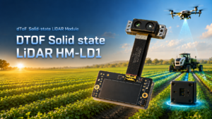
The DTOF Solid State LiDAR HM-LD1 is a compact SPAD dToF LiDAR module designed to output real-time depth images and 3D point cloud data. For UAV developers, robotics engineers, and embedded system teams, its low weight, low power consumption, multiple interfaces, and SDK support make it suitable for obstacle avoidance, distance detection, altitude-related sensing, terrain following experiments, robotic vision development, smart inspection prototypes, and SLAM research.
HM-LD1 supports indoor or nighttime ranging up to 25 m and outdoor daytime ranging up to 8 m, according to the provided product details. Its compact body, 28 g weight, and 1.2 W power consumption make it practical for small UAVs and embedded robotics platforms where payload and battery budget are limited. The module supports UART, UDP, and UVC interfaces, allowing integration with PCs, Raspberry Pi-class devices, flight-controller-adjacent systems, and embedded platforms depending on the project architecture.
Download DTOF SSL HM-LD1 Product Brochure
| Specification | DTOF Solid State LiDAR HM-LD1 |
|---|---|
| Product Name | DTOF Solid State LiDAR HM-LD1 |
| Technology | SPAD dToF solid-state LiDAR |
| Dimensions | 43.5 mm × 30 mm × 26.5 mm |
| Weight | 28 g |
| Indoor Ranging Capability | 0.5–25 m |
| Outdoor Ranging Capability | 0.2–8 m |
| Ranging Accuracy | ±3 cm |
| Field of View | 60° horizontal × 45° vertical |
| Resolution | 40 × 30 |
| Frame Rate | 10 fps |
| Interfaces | UART / UDP / UVC |
| Operating Temperature | -20 ℃ to 60 ℃ |
| Power Consumption | 1.2 W |
| Development Support | SDKs for x86 Windows, x86 Linux, and ARM Linux |
| Typical UAV/Robotics Uses | Obstacle avoidance, distance detection, autonomous navigation, UAV altitude hold, terrain following, robotic vision, smart inspection, SLAM research |
View Product Details & Pricing ➔
Why HM-LD1 Fits Compact UAV Development
HM-LD1 is well aligned with compact UAV development because its 28 g weight helps preserve flight time and payload margin. Its 1.2 W power consumption supports embedded integration without placing a heavy burden on the power system. The 60° horizontal by 45° vertical field of view can be useful for forward-facing obstacle sensing, downward-facing altitude-related sensing, or targeted inspection setups, depending on mounting and software design.
The module’s UART, UDP, and UVC interfaces provide multiple integration paths. Developers can test on PCs, integrate with embedded Linux platforms, or connect to systems that require serial or network-based communication. SDKs for x86 Windows, x86 Linux, and ARM Linux reduce development friction and make the module practical for prototyping, robotics education, algorithm testing, and UAV perception experiments.
Where HM-LD1 Is Not a Replacement for Survey-Grade LiDAR
HM-LD1 should be understood as a compact depth and point cloud module, not a complete georeferenced surveying payload. Full land surveying usually requires GNSS/INS, calibration, time synchronization, trajectory processing, ground validation, and specialized software. HM-LD1 is better positioned for UAV perception, obstacle detection, smart inspection, robotic development, autonomous navigation experiments, terrain-following prototypes, and embedded sensing projects.
LiDAR UAV Selection Checklist
- ✅ Mission type: Mapping, surveying, inspection, obstacle avoidance, SLAM, altitude sensing, or research?
- ✅ Required range: What distance must the LiDAR reliably measure indoors and outdoors?
- ✅ Accuracy requirement: Do you need centimeter-level distance sensing or survey-grade geospatial accuracy?
- ✅ Field of view: Is the sensor looking forward, downward, sideways, or covering multiple directions?
- ✅ Frame rate: Is the UAV moving slowly for inspection or quickly for autonomous navigation?
- ✅ Payload weight: Can the drone carry the sensor, processor, mount, cables, and power system?
- ✅ Power budget: Can the UAV provide stable power without reducing flight time too much?
- ✅ Interface: Does the system need UART, UDP, UVC, USB, Ethernet, or another protocol?
- ✅ Software support: Are SDKs, sample tools, and operating-system support available?
- ✅ Outdoor performance: Has the sensor been tested under expected sunlight and target reflectivity?
- ✅ Mechanical integration: Is the sensor protected from vibration, prop wash, and obstruction?
- ✅ Scaling path: Can the prototype evolve into a production or survey-grade workflow if needed?
Common Mistakes When Choosing a LiDAR UAV Sensor
Mistake 1: Buying for Maximum Range Only
Maximum range is important, but it is not the only decision factor. A long-range sensor with poor software support, excessive weight, limited FOV, high power consumption, or weak outdoor reliability may be a poor fit for a UAV. Evaluate usable range under expected conditions, not just the largest number in a specification sheet.
Mistake 2: Confusing Depth Sensing with Surveying
A LiDAR module can output depth or point cloud data without being a complete surveying system. Survey-grade deliverables require georeferencing, GNSS/INS, calibration, synchronization, and validation. Confusing these categories can lead to unrealistic expectations and failed projects.
Mistake 3: Ignoring Weight and Power
Payload mass and power consumption directly affect flight time, stability, thermal design, and platform selection. Small UAVs benefit from lightweight, low-power modules, especially during prototyping. Always calculate the full payload, including mounting and compute hardware.
Mistake 4: Not Testing Outdoor Conditions
Outdoor conditions can reduce usable range and measurement reliability. Bright sunlight, dark surfaces, reflective targets, dust, fog, rain, vibration, and temperature changes should all be considered. Test the sensor in the actual mission environment before relying on it for critical operation.
Mistake 5: Underestimating Software Integration
LiDAR data is only valuable if the system can read, synchronize, visualize, filter, and use it. SDKs, operating-system support, interface documentation, data formats, and example tools can save significant engineering time. Integration risk should be evaluated as seriously as sensor hardware specifications.
Final Thoughts: Match the LiDAR UAV Sensor to the Mission
A LiDAR UAV is not a single product category. It can mean a high-end mapping drone with GNSS/INS, a compact autonomy platform, an inspection UAV, or a research drone equipped with a lightweight depth sensor. The best choice depends on the mission. Surveying requires georeferenced accuracy, calibration, and post-processing. Obstacle avoidance requires low-latency perception and reliable detection. UAV research requires open interfaces, SDK support, manageable power consumption, and easy embedded integration.
For compact UAV perception and robotics development, the DTOF Solid State LiDAR HM-LD1 offers a practical example of a lightweight solid-state dToF module with real-time depth image and point cloud output, UART/UDP/UVC interfaces, SDK support, 28 g weight, and 1.2 W power consumption. For teams building drone autonomy, smart inspection, altitude sensing, and terrain-following prototypes, it can serve as an accessible starting point before scaling to larger UAV LiDAR systems.
Explore the DTOF Solid State LiDAR HM-LD1 or download the
HM-LD1 product brochure to evaluate its specifications for your UAV or robotics project.
FAQ: LiDAR UAV Buying and Integration Questions
What LiDAR UAV setup is best for beginners in drone mapping or surveying?
How do I choose a LiDAR sensor for a UAV when payload, budget, and accuracy are limited?
Are non-DJI UAVs suitable for LiDAR mapping under a limited budget?
Can a compact dToF LiDAR module be used for UAV obstacle avoidance?
What is the difference between a depth map and a point cloud in UAV LiDAR?
How important is LiDAR weight for a UAV?
Is outdoor LiDAR performance different from indoor performance?
Do I need GNSS/INS for every LiDAR UAV project?
📚 References & Further Reading
- Industry Standard: Sony LiDAR technology reference and Cepton Technologies LiDAR solutions
- Related Guide: What Is Multi-Band RTK GNSS?, RTK receptor vs receiver, and Tesla Autopilot camera and LiDAR test analysis






