


dToF LiDAR Imagery Explained: Depth Maps, Point Clouds, and Robot Vision Integration
Modern robots do not simply “see” the world with cameras. They need measurable 3D structure they can trust. Here’s the deal: for autonomous mobile robots, drones, smart inspection systems, industrial safety devices, service robots, and robot vacuums, the difference between recognizing an obstacle and knowing its actual distance can decide whether the machine behaves cleanly or becomes a liability. This is where dtof lidar imagery earns its place. By directly measuring the time it takes emitted light pulses to return from surrounding objects, dToF LiDAR turns real physical space into depth maps and point clouds that machines can use for obstacle avoidance, mapping, SLAM, altitude control, object detection, and practical spatial awareness.
Look, a camera can tell a robot that something looks like a box. A depth sensor helps the robot understand whether that box is 30 centimeters away, 3 meters away, or hanging halfway off a shelf. That difference matters in the shop, in a warehouse aisle, on a UAV inspection route, and inside any product where a machine has to move around people or equipment. dToF LiDAR imagery gives the robot a clean geometric layer to work from, especially when color images are not enough.
This guide explains dToF LiDAR imagery from the ground up: how direct time-of-flight sensing works, how depth maps differ from point clouds, how robot vision systems consume LiDAR data, and what engineers should evaluate before integrating a compact solid-state dToF module. We will also examine real specifications from the DTOF Solid State LiDAR HM-LD1, including range, field of view, resolution, frame rate, interfaces, weight, and power consumption, so developers can connect the concepts to an actual embeddable sensor module for robots, drones, security systems, and industrial perception applications.
If you are building a robot vision system, the goal is not to collect fancy sensor data for its own sake. The goal is to make better decisions at the controller level. A depth frame that never affects speed, braking, docking, mapping, or inspection logic is just a pretty picture. A well-integrated dToF LiDAR stream, on the other hand, becomes a hard-working part of the perception stack.
Table of Contents
- 👉 What Is dToF LiDAR Imagery?
- 👉 How dToF LiDAR Works
- 👉 Depth Maps vs. Point Clouds
- 👉 How Robots Use dToF LiDAR Imagery
- 👉 dToF vs. iToF vs. Traditional LiDAR
- 👉 What Determines dToF LiDAR Image Quality?
- 👉 Integration Workflow for Robotics Developers
- 👉 DTOF Solid State LiDAR HM-LD1 Specifications
- 👉 Industrial and Robotic Application Scenarios
- 👉 dToF LiDAR Module Selection Checklist
- 👉 FAQ: dToF LiDAR Imagery
- 👉 Conclusion: Turning dToF LiDAR Imagery into Robot Intelligence
What Is dToF LiDAR Imagery?
dToF means direct time-of-flight, while LiDAR means Light Detection and Ranging. In plain language, dToF LiDAR emits light pulses, usually in the infrared spectrum, and measures the direct return time of photons reflected from objects in the environment. The physics principle is based on time-of-flight measurement, where distance is inferred from the travel time of a signal. Instead of guessing distance from image texture, apparent object size, or stereo disparity alone, dToF sensing measures range as a physical quantity.
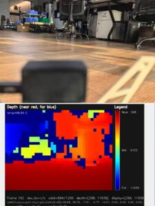
dToF LiDAR imagery is not the same thing as a conventional camera photograph. A standard RGB camera records color and intensity. A dToF LiDAR module records distance. Its output may appear as a grayscale depth image, a colored heatmap, a distance matrix, an obstacle map, or a 3D point cloud, but the underlying value is spatial range. Each pixel or sample represents how far a surface is from the sensor, not what color that surface is.
For a broader introduction to LiDAR principles, see our guide: LiDAR Definition: What It Is and How It Works. That foundation is useful because dToF LiDAR imagery is one of the most practical ways to turn LiDAR ranging into machine-readable perception data for embedded robotics.
Why “Imagery” Does Not Always Mean RGB Images
In robotics and industrial automation, the word “image” often means any structured sensor frame. A thermal image is temperature-based. A depth image is distance-based. A dToF depth map can be visualized like an image, but it is fundamentally a numerical array. A nearby object may appear bright, dark, red, blue, or another color depending on the visualization palette, but that color is only there so a human can understand it quickly. The robot uses the numerical distance values.
In the shop, this distinction matters. Operators may look at a colored depth display and say, “The red area is close.” The software does not care about red. It cares that a zone reports 0.65 m, 1.2 m, or 4.8 m. That range value gets compared against thresholds, fused with other sensors, projected into a robot coordinate frame, and used to make control decisions.
Why dToF Imagery Matters in Robotics
Robots need to understand walls, shelves, people, machines, ground planes, openings, steps, docking stations, pallets, and terrain. RGB imagery can help classify objects, but distance information is needed to act safely. dToF LiDAR imagery enables obstacle avoidance, local mapping, SLAM support, volumetric measurement, safety zone monitoring, cliff detection, robot docking, UAV altitude control, and terrain following. In low-light or low-texture scenes where cameras may struggle, depth sensing can give a robot direct geometric evidence about the environment.
Here’s the deal with real deployment: the environment will not always cooperate. Floors get glossy. People walk through the aisle. Pallets show up where nobody planned for them. Lighting changes. Dust, vibration, sunlight, glass, and dark materials all show up eventually. A well-chosen dToF LiDAR module gives the system another reliable way to understand distance when visual-only perception gets shaky.
How dToF LiDAR Works
A dToF LiDAR system works by emitting very short light pulses and measuring how long it takes for reflected photons to return to the receiver. Because the speed of light is known, the system can calculate the distance to the reflecting surface. The distance calculation follows a simple physical relationship: distance equals the speed of light multiplied by the measured round-trip time, divided by two. The division by two is required because the measured time includes both the outgoing path from the emitter to the object and the return path from the object back to the receiver.
Photon Emission and Return Detection
The emission stage sends controlled light pulses into the scene. When the pulses hit an object, part of the energy reflects toward the sensor. The receiver optics collect returning photons and direct them onto a detector. In modern compact solid-state dToF LiDAR modules, a SPAD sensor, or single-photon avalanche diode, may be used because it can detect extremely weak photon returns with high timing sensitivity. That is valuable for small modules where optical aperture, power budget, and packaging space are limited.
The reflected signal can vary widely depending on distance, surface reflectivity, incidence angle, ambient light, and optical interference. A white wall may return a stronger signal than black rubber. A matte cardboard box may behave differently from glass or polished metal. Good dToF implementation therefore depends not only on the detector but also on optical design, timing electronics, filtering, calibration, and signal processing.
Look at it like any measurement system on a production line. The sensor head matters, but so does the installation, the material being measured, the environment, and the processing behind the scenes. If a robot is expected to detect black forklift tires under mixed lighting, that has to be tested. If a UAV is expected to hold altitude above grass, gravel, concrete, and wet surfaces, that has to be tested too.
From Time Measurement to Distance Data
The sensor electronics measure photon arrival times in very fine time bins. These time measurements are processed into distance values. When the sensor has an array of measurement zones or pixels, it builds a grid of distance samples. That grid becomes a depth frame. At a 40 × 30 resolution, for example, each frame contains 1,200 distance samples. At 10 frames per second, the host system receives repeated depth snapshots that can be filtered, tracked, and converted into navigation decisions.
Those snapshots are where the practical value starts. One frame may show a clean aisle. The next few frames may show a moving person entering the robot’s planned path. The robot does not need a high-resolution photograph to understand the risk. It needs enough spatial information, with acceptable latency and accuracy, to slow down, stop, steer, or flag the controller.
Why SPAD dToF Is Useful for Compact Solid-State LiDAR
SPAD-based dToF is well suited for compact solid-state LiDAR because it avoids bulky rotating mechanisms while still providing useful depth imagery. Solid-state modules can be integrated into flat robot housings, embedded cameras, UAV payloads, inspection devices, and safety equipment. The lack of a traditional mechanical scanning tower can reduce mechanical complexity, simplify industrial design, and improve packaging flexibility. For developers, this means dToF LiDAR imagery can be treated as a compact perception input rather than a large external sensing assembly.
That packaging advantage is not just cosmetic. It can reduce snag points, lower the overall product height, simplify weather sealing, improve shock tolerance, and make the finished robot easier to manufacture. On small platforms, a few millimeters of height and a few grams of weight can matter more than people expect.
Depth Maps vs. Point Clouds
Two of the most important output formats in dToF LiDAR imagery are the depth map and the point cloud. They can be generated from the same underlying range data, but they serve different engineering purposes. A depth map is a two-dimensional image-like array in which every pixel stores a distance value. A point cloud is a three-dimensional set of points, usually represented as X, Y, and Z coordinates in a sensor or robot coordinate frame.
| Data Type | Structure | Best For | Typical Robotics Use |
|---|---|---|---|
| Depth Map | 2D pixel grid with distance value per pixel | Fast image-style processing | Obstacle detection, segmentation, presence detection |
| Point Cloud | 3D coordinates such as X, Y, Z | Spatial mapping and geometric analysis | SLAM, navigation, volume measurement, 3D reconstruction |
What a dToF Depth Map Represents
A dToF depth map represents distance across the sensor’s field of view. If a robot is facing a wall, the depth values may be relatively uniform. If a person stands in front of the wall, the person’s body creates nearer depth values. If a doorway or opening appears, some areas may show longer range values or invalid readings depending on what lies beyond. A depth map is useful because it preserves a grid structure, allowing developers to apply image-style processing such as thresholding, region segmentation, blob detection, morphology, and temporal filtering.
For many embedded systems, that grid structure is the fastest path to useful behavior. A developer can divide the depth frame into regions of interest, check minimum or median distances in each zone, reject noisy pixels, and create simple but reliable response logic. That may not sound glamorous, but it is exactly the kind of method that keeps small robots dependable.
How Depth Pixels Become 3D Points
To convert depth pixels into a point cloud, the system uses sensor geometry and calibration parameters. Each pixel corresponds to a viewing direction. The measured distance along that direction can be projected into a 3D coordinate. Once the sensor’s position and orientation relative to the robot frame are known, the data can be transformed into robot coordinates. This allows the robot to understand whether an obstacle is directly ahead, below the sensor, above the floor plane, or inside a protected zone.
That coordinate transform is not optional. If the sensor is tilted downward by 12 degrees but the software assumes it is level, every point cloud and obstacle zone will be wrong. The robot may think the floor is an obstacle, miss a real obstacle, or build a distorted local map. In the shop, this is one of those details that separates a demo from a product.
When to Use Depth Maps and When to Use Point Clouds
Depth maps are usually preferable when the task can be solved in image space. Examples include detecting whether an object appears within a region, checking the nearest distance in a forward zone, or identifying presence in a smart camera application. Point clouds are preferable when geometry matters: measuring object volume, estimating surface planes, building maps, calculating obstacle height, or integrating with 3D SLAM pipelines. In many real systems, engineers use both. The depth map supports fast local detection, while the point cloud supports higher-level spatial reasoning.
A practical robot may use a depth map for immediate braking and a point cloud for mapping. A smart security device may only need the depth map. An inspection robot may need point clouds for geometry measurement and raw depth logs for debugging. The right answer depends on the job, not on which output format sounds more advanced.
How Robots Use dToF LiDAR Imagery
Robot vision is not only about recognizing labels such as “person,” “box,” or “chair.” It is also about understanding where objects are in physical space and whether the robot can move safely. dToF LiDAR imagery gives the perception stack direct range data, which can be used for obstacle avoidance, free-space detection, wall following, docking, cliff detection, terrain following, human presence detection, robotic arm distance checking, safety zone monitoring, and SLAM assistance.
Obstacle Avoidance and Free-Space Detection
For an AMR or service robot, a forward-facing dToF module can monitor the space in front of the chassis. The perception software can define regions of interest, such as a near stop zone, a warning zone, and a normal navigation zone. If depth values inside the stop zone fall below a threshold, the robot can slow down or halt. Unlike a single-point range sensor, dToF LiDAR imagery provides spatial structure, allowing the robot to distinguish a small obstacle from a broad wall, detect partial occlusions, or identify an opening.
Here’s a common example. A single range sensor might report that something is 0.8 m away. That tells the robot something is close, but not whether it is a chair leg, a wall, a person’s foot, or a narrow post near the left edge. A depth frame gives more context. The software can see whether the object occupies one corner of the field, the center, or the whole lower half of the view. That extra structure allows better behavior.
SLAM, Mapping, and Localization Support
dToF depth data can support mapping and localization by providing local geometry. Depending on the algorithm and field of view, the data may be used to detect walls, planes, shelves, corridor boundaries, or landmarks. It can also help improve behavior in situations where RGB cameras have limited texture, such as blank walls, low-light areas, or repetitive industrial surfaces. However, the sensor should be evaluated within the complete SLAM architecture, including range, frame rate, FOV, resolution, timing, and synchronization.
SLAM is never just a sensor problem. It is a timing problem, a calibration problem, a compute problem, and a motion problem. If timestamps drift, if the sensor is mounted poorly, or if the robot moves too fast for the frame rate, mapping quality will suffer. dToF LiDAR can provide useful geometry, but the surrounding system still has to be engineered correctly.
Sensor Fusion with Cameras, IMUs, and Odometry
Most production robots do not rely on a single sensor. dToF LiDAR imagery can be fused with RGB cameras, IMUs, wheel encoders, GNSS, visual inertial odometry, and other LiDAR sensors. The depth sensor may provide short- to mid-range geometric confirmation, while a camera provides classification, an IMU provides motion dynamics, and wheel odometry provides local displacement. For systems combining visual inertial odometry and wheel data, see: VIO with Global Shutter and Odometer. The practical goal is not to make one sensor do everything, but to create a robust perception stack that remains reliable across lighting, texture, motion, and environmental variation.
Look, redundancy is not waste when robots are operating around people, vehicles, shelves, or expensive equipment. A camera may classify a person. A dToF LiDAR may confirm that the person is inside a stop zone. Wheel odometry may report that the robot is still rolling. The controller can then make a better decision than any one sensor could make alone.
dToF vs. iToF vs. Traditional LiDAR
dToF LiDAR, iToF sensing, and traditional mechanical LiDAR are often discussed together because all relate to depth or ranging. However, they differ in measurement principle, packaging, output behavior, and best-fit applications. dToF measures the direct travel time of emitted light pulses. iToF, or indirect time-of-flight, estimates distance by measuring phase shift between emitted and received modulated light. Traditional mechanical LiDAR often uses spinning or scanning parts to generate wide angular coverage, including 2D or 360-degree scans.
| Technology | Measurement Method | Typical Strengths | Design Considerations |
|---|---|---|---|
| dToF LiDAR | Direct photon return time | Accurate ranging, depth maps, point clouds, compact solid-state designs | FOV, resolution, range, and frame rate must match application needs |
| iToF Sensor | Phase shift between emitted and received modulated light | Good for short-range depth imaging and consumer depth cameras | Can be affected by multi-path interference and phase ambiguity |
| Mechanical LiDAR | Scanning laser measurement using moving components | Wide coverage, often 2D or 360-degree scanning | Mechanical size, moving parts, height, and integration constraints |
Why dToF Is Not Just a Proximity Sensor
A basic proximity sensor may return one distance value or a small number of detection zones. dToF LiDAR imagery provides a structured set of measurements across a field of view. That difference matters for robots because a single distance value cannot describe the shape, size, or position of an obstacle. A depth image can show whether an object occupies the left side, right side, upper field, or lower field of the sensor view, enabling more intelligent decisions.
This is the difference between knowing “something is close” and knowing “something is close on the lower right side of the forward field.” The second statement is much more useful for steering, docking, clearance checking, and safety-zone logic.
When a Solid-State dToF Module Makes More Sense
A solid-state dToF module makes sense when the product requires compact integration, low weight, low power, and depth imagery within a defined field of view. Examples include drones, compact AMRs, smart cameras, robot vacuums, embedded inspection systems, safety devices, and robotic perception prototypes. Solid-state designs can also reduce concerns related to rotating assemblies, external towers, and mechanical wear.
In product design, fewer moving parts usually means fewer mechanical headaches. That does not automatically make solid-state better for every application, but it does make it attractive where package size, sealing, shock, vibration, and styling are important. For embedded devices, that can be the deciding factor.
When a Traditional Scanning LiDAR May Still Be Needed
Traditional scanning LiDAR may still be needed when the application requires wide panoramic coverage, long-range outdoor mapping, or mature compatibility with existing 2D navigation stacks. In some robots, a scanning LiDAR and a dToF depth module can be complementary. The scanning LiDAR may provide wide-area localization, while the dToF module provides local 3D obstacle detection, docking support, or short-range perception in blind zones.
The smartest architecture is often mixed. Use the sensor that fits the job. A 360-degree scanner can be excellent for planar mapping, while a forward dToF module can catch low obstacles, ramps, feet, cables, or docking features that a planar scan may miss.
What Determines dToF LiDAR Image Quality?
The quality of dToF LiDAR imagery is influenced by more than the maximum range number on a datasheet. Engineers should evaluate range, accuracy, resolution, frame rate, field of view, ambient light tolerance, target reflectivity, multipath reflections, calibration, signal processing, interface bandwidth, thermal stability, power budget, and mechanical placement. A sensor that performs well in a laboratory may behave differently outdoors, near glass, on black materials, or inside reflective industrial environments.
Range and Accuracy
Maximum range describes how far the sensor can detect under specified conditions, but accuracy describes how close the reported measurement is to the true distance. For navigation and safety applications, accuracy at the working distance is more important than maximum range alone. A robot moving through a warehouse may need reliable distance measurements to pallets and people at several meters. A UAV may need stable altitude information relative to terrain. An inspection system may need consistent measurement repeatability across surfaces.
Here’s the deal with range claims: always check the conditions. Indoor range, outdoor range, reflectivity, sunlight, target size, and confidence thresholds all matter. A sensor that sees a white wall at 25 m indoors may not behave the same way against dark rubber in direct sunlight. Good engineering means validating the actual application, not just reading the headline number.
Resolution and Frame Rate
Resolution determines how many depth samples are available in each frame. A 40 × 30 depth grid can be suitable for obstacle detection, distance mapping, presence sensing, zone monitoring, and embedded perception tasks where compactness and bandwidth are important. However, high-speed manipulation, fine object contouring, and dense 3D reconstruction may require higher spatial density. Frame rate determines how often the robot receives updated depth information. At 10 fps, developers must consider robot speed, stopping distance, filtering latency, and control loop timing.
A slow-moving inspection robot may be perfectly comfortable with 10 fps. A fast indoor drone may need tighter control loops and careful filtering. A safety device may care more about consistent detection than dense resolution. The right answer depends on speed, payload, braking distance, and acceptable reaction time.
Field of View and Coverage
Field of view determines the angular area covered by the sensor. A wider field of view can detect more of the environment, but it also spreads resolution across a larger area. A narrower field can concentrate measurements but may miss side obstacles. Mounting position is therefore critical. A forward-facing sensor may support obstacle avoidance, while a downward-facing sensor may support altitude hold, cliff detection, or terrain following. Blind zones should be identified early during mechanical design.
In the shop, poor placement causes more trouble than people admit. A sensor hidden behind a tinted cover, blocked by a bumper lip, aimed too high, or mounted where vibration is severe can underperform even if the sensor itself is good. Mechanical, optical, and software teams should agree on the field of view before the housing is locked down.
Outdoor Sunlight and Surface Reflectivity
Outdoor sunlight can introduce strong ambient optical noise, especially under clear daytime conditions. Target reflectivity also changes signal strength. Matte white surfaces, dark rubber, transparent glass, wet floors, and shiny metals can behave differently. Multipath reflections may occur when light bounces from multiple surfaces before returning to the receiver, potentially creating measurement ambiguity. For industrial robots and UAVs, validation should include real surfaces, real lighting, real motion, and the expected operating temperature range.
Do not test only against a clean white wall in a lab and call the job done. Test cardboard, black plastic, polished metal, glass, painted concrete, asphalt, tile, wood, fabric, and whatever else the robot will see. If the robot will work outside, test in sun, shade, dawn, dusk, and changing weather conditions where possible.
Processing Pipeline and Host Compute
The host processor must handle frame acquisition, filtering, coordinate transformation, obstacle extraction, sensor fusion, and decision logic. Some tasks can run efficiently on embedded CPUs. More complex workloads, such as dense mapping, neural network inference, or multi-sensor SLAM, may benefit from GPUs or accelerators. For perception workloads that combine depth processing, SLAM, and neural inference, compare host compute options in: CPU vs GPU: Choosing for SLAM. Interface bandwidth also matters because raw depth frames, point clouds, and synchronized sensor streams must move reliably through the system.
For readers comparing broader sensing ecosystems, companies such as domisensor also provide useful context on industrial sensor technologies.
Integration Workflow for Robotics Developers
A successful dToF LiDAR integration begins with the perception objective. Engineers should define what the sensor must accomplish before selecting mounting, interface, and software architecture. Is the goal obstacle detection, local mapping, SLAM support, altitude hold, terrain following, intrusion detection, volume measurement, docking alignment, or human presence detection? Each objective drives different requirements for field of view, range, update rate, accuracy, and output format.
Step 1: Choose the Right Output Format
⚙️ If the application needs fast thresholding or region-based detection, a depth map may be the most efficient output. If the application needs geometry, surface planes, object volume, or 3D mapping, a point cloud may be more appropriate. Many systems begin with raw depth frames for debugging, then add filtering, calibration, and point cloud projection after basic communication is stable.
⚙️ A good first milestone is simple visualization. Get the depth frame on screen. Confirm that near objects look near, far objects look far, and invalid zones are understood. Once the raw stream makes sense, then move into filtering, transforms, and robot behavior.
Step 2: Connect Through UART, UDP, or UVC
⚙️ Interface selection affects integration complexity. UART is useful for embedded controllers and simpler data exchange. UDP is suitable for network-based streaming, especially where a companion computer or Ethernet architecture is already present. UVC can simplify integration with PC-like camera pipelines because the sensor can be treated similarly to a video device. The best interface depends on the host platform, required data rate, software stack, and deployment environment.
⚙️ Do not pick an interface just because it is familiar. Check latency, cable length, connector reliability, operating system support, driver availability, and how the data will be timestamped. These details show up fast once the robot starts moving.
Step 3: Convert Depth Frames into Robot Coordinates
⚙️ The sensor must be calibrated relative to the robot body. This means determining its position, orientation, and coordinate transform relative to the robot frame. Without this step, the robot may know that something is visible in the sensor frame but not know where it is relative to the chassis, wheels, arm, or flight controller. Coordinate conversion is also essential when fusing dToF data with IMU, odometry, camera, or GNSS information.
⚙️ Treat calibration like production work, not a one-time lab trick. If the module can shift during assembly, shipping, or service, the system needs mechanical locating features, verification procedures, or software compensation.
Step 4: Validate with Real Obstacle and Navigation Tests
⚙️ Testing should include realistic obstacles, lighting, target materials, vibration, motion, temperature, and operating distance. Engineers should log raw depth frames and point cloud data so that failures can be diagnosed later. A good validation process includes indoor static tests, controlled motion tests, outdoor lighting tests, edge-case surface tests, and full system navigation tests. The most common integration issues are not caused by the sensor alone but by timing mismatch, poor mounting angle, insufficient filtering, incorrect coordinate transforms, unrealistic test surfaces, or control logic that reacts too slowly.
⚙️ Logging is your friend. When a robot makes a bad decision, raw data logs are often the only way to know whether the sensor missed the object, the filter rejected it, the transform was wrong, or the controller reacted too late.
DTOF Solid State LiDAR HM-LD1 Specifications
The DTOF Solid State LiDAR HM-LD1 is a compact solid-state LiDAR module based on SPAD dToF technology. It provides real-time depth images and 3D point cloud data for obstacle avoidance, distance detection, autonomous navigation, smart inspection, and robot vision development. Its small size, low weight, multiple interfaces, and SDK support make it suitable for robots, UAVs, embedded vision devices, security systems, and industrial inspection platforms.
View Product Details & Pricing ➔
Mechanical and Ranging Specifications
| Specification | DTOF Solid State LiDAR HM-LD1 |
|---|---|
| Dimension | 43.5 mm × 30 mm × 26.5 mm |
| Ranging Capability | Indoor: 0.5–25 m; Outdoor: 0.2–8 m |
| Ranging Accuracy | ±3 cm |
| Field of View | 60° horizontal × 45° vertical |
| Weight | 28 g |
Depth Imaging and Integration Specifications
| Specification | DTOF Solid State LiDAR HM-LD1 |
|---|---|
| Resolution | 40 × 30 |
| Frame Rate | 10 fps |
| Interface | UART / UDP / UVC |
| Operating Temperature | -20 ℃ to 60 ℃ |
| Power Consumption | 1.2 W |
Developers can also download the DTOF SSL HM-LD1 product brochure for additional integration details.
Why HM-LD1 Fits Embedded Robot Vision
HM-LD1 is designed for embedded perception where mechanical space, power budget, and weight are constrained. With a 28 g weight and 1.2 W power consumption, it can fit into mobile robots, UAV payloads, smart cameras, compact inspection devices, and robotic development platforms. Its solid-state architecture also helps product teams avoid the height and packaging challenges associated with some traditional LiDAR towers.
For engineers working on small platforms, those numbers matter. A 28 g module is much easier to place on a drone, small service robot, or compact inspection head than a bulky scanning assembly. A 1.2 W power draw is also easier to budget on battery-powered systems where every watt has to justify itself.
Depth Map and Point Cloud Output
The HM-LD1 supports real-time depth images and 3D point cloud data, making it useful for both image-style and geometry-style processing. Developers can use depth maps for fast obstacle detection, presence monitoring, or region-based distance checks. They can use point cloud data for spatial analysis, robot navigation support, volume measurement, inspection, and mapping-related development.
This dual-output approach is useful during development. A team can start with depth-map visualization, create zone logic, then project point clouds when the application calls for 3D geometry. It gives developers room to grow without changing the sensing hardware early in the project.
Supported Development Platforms
MRP offers SDKs for x86 Windows, x86 Linux, and ARM Linux, enabling development and integration across diverse operating systems and architectures. This is important for robotics teams because prototypes may begin on a Windows or Linux PC and later move to ARM-based embedded computing platforms, Raspberry Pi-class systems, or UAV companion computers.
That development path is common. Teams often debug on a laptop, prototype on a bench computer, then deploy on embedded Linux. Having software support across those stages lowers integration friction and helps keep the perception stack consistent.
Indoor and Outdoor Ranging Performance
The HM-LD1 supports indoor ranging from 0.5 m to 25 m and outdoor ranging from 0.2 m to 8 m. It is described as highly accurate, including outdoor measurement at distances up to 8 m on a clear summer day under approximately 80,000 lux conditions. This makes it relevant for measuring distances to objects that may be difficult or unsafe for people to approach, such as bridges, expressways, dams, and industrial infrastructure.
Outdoor ranging should always be validated in the target environment, but those specifications make the module interesting for field robotics, UAV inspection, and industrial measurement tasks where compact packaging and direct range data are both important.
Industrial and Robotic Application Scenarios
dToF LiDAR imagery is valuable wherever a machine needs compact, direct, and structured distance perception. Because the output can be interpreted as a depth image or point cloud, the same sensing principle can support multiple industries, from mobile robotics to UAV inspection, smart security, and industrial automation.
Autonomous Mobile Robots and Service Robots
AMRs and service robots can use dToF modules for front obstacle detection, side clearance checks, docking alignment, wall following, low-height obstacle detection, and human presence monitoring. In a warehouse, a robot may need to detect pallet edges, people, carts, racks, and temporary obstructions. In a hospital or office, a service robot may need to detect furniture, glass partitions, or people entering its path. A compact dToF module can provide localized 3D perception without requiring a bulky sensing package.
In the shop, this kind of sensor is often used to close the gaps left by other systems. A 2D scanner may handle navigation. Cameras may identify objects. dToF LiDAR can add localized depth where the robot needs extra confidence, such as near the bumper, around a docking station, or at shelf height.
UAV Altitude Hold and Terrain Following
For UAVs, depth sensing can support altitude hold, landing assistance, terrain following, and obstacle awareness. A downward-facing dToF sensor can help estimate distance to the ground, while a forward-facing module can assist with obstacle detection during inspection flights. Low weight is especially important because every gram can affect flight time, payload capacity, and system endurance.
UAV integration also puts pressure on vibration control, timing, and sunlight tolerance. A sensor that works on a bench still has to work on an airframe with propeller vibration, rapid attitude changes, and shifting outdoor light. Proper mounting and data filtering are just as important as the sensor selection.
Smart Security and Zone Intrusion Monitoring
In security and safety systems, dToF LiDAR imagery can define protected zones and detect whether a person or object enters them. Unlike a simple motion sensor, a depth sensor can estimate where the target is within the field of view and how far it is from the device. This is useful for access control, machine safety monitoring, people counting, smart cameras, and presence detection.
A depth-based zone can also reduce nuisance triggers when designed correctly. Instead of responding to any motion, the system can respond to objects entering a defined distance region. That is useful around doors, machines, counters, restricted aisles, and equipment where simple motion detection is too blunt.
Inspection, Measurement, and Industrial Automation
Industrial inspection systems can use dToF data for distance detection, object recognition support, volume measurement, and smart inspection. For bridges, expressways, dams, and other infrastructure, compact ranging modules can help measure distances to surfaces that are difficult to approach manually. In factories, dToF sensors can support robotic arms, automated guided vehicles, material handling systems, and machine safety zones.
For robotic arms, dToF imagery can help with approach distance, presence checks, and workspace monitoring. For AGVs and AMRs, it can improve local obstacle detection. For fixed inspection stations, it can confirm part presence, approximate shape, fill level, or object position. The same basic data type, distance over a field of view, can be used in many practical ways.
dToF LiDAR Module Selection Checklist
Choosing a dToF LiDAR module is an engineering decision, not just a purchasing decision. The best module is the one that meets the application’s perception objective, mechanical constraints, software stack, environmental conditions, and validation requirements.
- ✅ Range: Does the sensor meet indoor and outdoor distance requirements?
- ✅ Accuracy: Is the error acceptable for navigation, inspection, or detection?
- ✅ Field of View: Does the FOV cover the required detection zone?
- ✅ Resolution: Is the depth grid dense enough for the target object size?
- ✅ Frame Rate: Can the robot react fast enough at its operating speed?
- ✅ Interface: Does the host platform support UART, UDP, or UVC?
- ✅ SDK: Are Windows, Linux, or ARM Linux tools available?
- ✅ Size and Weight: Can it fit inside the mechanical envelope?
- ✅ Power: Is the power budget acceptable for mobile robots or UAVs?
- ✅ Environment: Has it been tested under sunlight, temperature, dust, and target reflectivity conditions?
Questions to Ask Before Prototyping
Before ordering modules, define the minimum and maximum detection distance, target object size, robot speed, expected lighting conditions, acceptable false detection rate, host platform, and desired output format. Confirm whether the system requires raw depth maps, point clouds, simple distance zones, or all of these. Also confirm whether the mounting position allows the required field of view without being blocked by the chassis, propellers, covers, or decorative housing.
Here’s a practical rule: write down the actual detection case before buying hardware. “Detect obstacles” is not enough. “Detect a 120 mm tall object from 0.3 m to 2.5 m while the robot moves at 0.8 m/s on an indoor warehouse floor” is much better. The clearer the requirement, the easier it is to pick and validate the sensor.
Common Integration Mistakes
Common mistakes include selecting a sensor based only on maximum range, ignoring outdoor sunlight conditions, mounting the sensor too low or too high, failing to calibrate the sensor pose, using insufficient filtering, and testing only with easy high-reflectivity targets. Another frequent issue is treating depth frames like perfect truth. Real dToF data should be filtered, validated, and fused with other signals when used for safety-critical behavior.
Look, every sensor has edge cases. The job is not to pretend they do not exist. The job is to understand them, design around them, test them, and make sure the controller behaves safely when readings are noisy, missing, delayed, or inconsistent.
Testing Procedure for Real-World Validation
A practical validation procedure should begin with basic communication and visualization. Next, test known distances with different surfaces. Then test dynamic obstacles and robot motion. After that, validate in the intended environment: warehouse, outdoor inspection site, UAV test field, office, factory, or smart security installation. Finally, log data during long-duration operation to identify thermal effects, vibration issues, rare false positives, and edge cases.
⚙️ Start on the bench, but do not stay there. Move from bench tests to controlled field tests, then to full system tests. If the sensor is going into a robot, test it on the moving robot. If it is going outdoors, test it outdoors. If it must survive vibration, test it with vibration. That is how you turn a promising module into a reliable subsystem.
FAQ: dToF LiDAR Imagery
Are all ToF sensors considered LiDAR, and what makes dToF LiDAR imagery different?
Can dToF LiDAR replace a traditional LiDAR tower in compact robots or robot vacuums?
How can developers test dToF LiDAR imagery with Raspberry Pi, Jetson, ROS, or UAV mapping systems?
Conclusion: Turning dToF LiDAR Imagery into Robot Intelligence
dToF LiDAR imagery converts physical space into measurable depth data that robots, UAVs, smart cameras, and industrial systems can use for perception and decision-making. Depth maps are useful for fast image-style processing, obstacle detection, presence sensing, and zone monitoring. Point clouds are useful for spatial reasoning, mapping, volume measurement, and 3D analysis. When combined with RGB cameras, IMUs, odometry, SLAM algorithms, and host compute resources, dToF LiDAR can become a practical part of a robust robot vision stack.
Here’s the deal: the value is not just in the sensor. The value comes from the whole chain: optical measurement, reliable mounting, correct calibration, usable software interfaces, good filtering, clean coordinate transforms, and field validation. When those pieces are handled properly, dToF LiDAR imagery becomes more than a visualization. It becomes actionable machine perception.
Compact solid-state modules such as the DTOF Solid State LiDAR HM-LD1 make dToF practical for embedded robotics, UAVs, inspection systems, smart devices, and industrial automation platforms. If you are developing a robot, UAV, smart camera, or industrial sensing system that requires compact depth perception, explore the DTOF Solid State LiDAR HM-LD1 or download the HM-LD1 product brochure for integration details.
📚 References & Further Reading
- Industry Standard: time-of-flight measurement
- Related Guide: LiDAR Definition: What It Is and How It Works
- Related Guide: CPU vs GPU: Choosing for SLAM
- Related Guide: VIO with Global Shutter and Odometer
- Product Resource: DTOF Solid State LiDAR HM-LD1






