


Tesla Autopilot Camera LiDAR Test: What Engineers Can Learn About Safer Robot Perception
The phrase tesla autopilot camera lidar test gets attention for a reason. It lands right in the middle of one of the hardest questions in autonomy: can a vision-led system understand the world safely without direct 3D ranging, or should LiDAR be part of the perception stack? Online debates usually circle around whether a specific test was fair, whether Autopilot or FSD was actually active, whether the target setup was artificial, or whether a staged wall represents a realistic road hazard. Those questions are fair. But for industrial engineers, the bigger issue is more useful: what should a perception system do when visual appearance, physical geometry, lighting, and software confidence do not line up cleanly?
Here’s the deal. This guide treats the Tesla Autopilot camera LiDAR test as an engineering case study, not a brand attack. Cameras bring rich semantic information: color, texture, signs, lane markings, object appearance, and scene context. LiDAR brings direct geometric distance information that can support obstacle detection, depth maps, point clouds, SLAM, altitude hold, zone intrusion monitoring, and robot navigation. For robotics teams, UAV developers, AMR integrators, and embedded autonomy designers, the practical question is not “camera versus LiDAR” as a slogan. The real question is how to build measurable, repeatable, and safer perception systems using the right sensor mix for the actual operating domain.
Table of Contents
- 👉 Why the Tesla Autopilot Camera LiDAR Test Matters
- 👉 Camera vs LiDAR: What Each Sensor Actually Measures
- 👉 What Engineers Should Examine in Any Autonomy Test
- 👉 Robot Perception Lessons Beyond Passenger Cars
- 👉 How dToF Solid-State LiDAR Works
- 👉 DTOF Solid State LiDAR HM-LD1 Specs
- 👉 Integration Workflow for Robots, UAVs, and Embedded Platforms
- 👉 Engineering Validation Checklist
- 👉 How to Choose a LiDAR Module for Industrial Robots
- 👉 Conclusion
- 👉 FAQ
Why the Tesla Autopilot Camera LiDAR Test Matters
The public debate around the Tesla Autopilot camera LiDAR test is useful because it exposes a problem engineers see all the time: people confuse a dramatic demo with a complete safety argument. A single test can reveal a meaningful edge case, but it cannot fully prove or disprove an entire perception strategy. Look, any serious engineer needs to get past the headline and ask what the test controlled, what it measured, what software mode was active, what data was logged, and whether the result can be repeated under different conditions.
The Public Debate Is About More Than One Vehicle
Many online arguments shrink the topic into two lazy claims: camera-only autonomy is unsafe, or LiDAR is unnecessary. Neither statement is technically complete. Camera systems can be extremely capable when trained on large datasets and backed by strong validation. LiDAR systems can provide direct geometry, but they still need calibration, filtering, interpretation, and the right system response. In the shop, nobody gets paid for slogans. Sensor physics, scenario design, data fusion, validation coverage, and fail-safe behavior are what actually matter.
For professional positioning, measurement, and perception context, companies such as Trimble show how industrial-grade systems rely on measurable data, calibration, and deployment-specific validation. In robotics, that same mindset applies whether the platform is an AMR, AGV, UAV, inspection robot, security device, or embedded vision system.
The Engineering Lesson Is About Uncertainty
Real-world autonomy is full of uncertainty: lighting, glare, weather, low texture, transparent materials, motion blur, occlusion, reflectivity, vibration, and unfamiliar objects. A camera may see a scene that looks visually plausible but is geometrically unsafe. A LiDAR may measure a surface accurately but lack semantic understanding of what the object actually is. A robust robot perception architecture should define how the system behaves when confidence is low, when sensors disagree, or when one data source becomes unreliable. For future internal content, this section is a strong place to link to a Robot LiDAR Solutions page or an autonomous navigation guide.
Camera vs LiDAR: What Each Sensor Actually Measures
To understand why the Tesla Autopilot camera LiDAR test became so controversial, engineers first need to separate semantic perception from geometric perception. A camera and a LiDAR do not measure the same thing. They can both support autonomy, but they give the control system different evidence about the environment. That difference matters when the robot has to decide whether to keep moving, slow down, stop, or ask for another layer of confirmation.
Cameras Provide Rich Visual Semantics
Cameras capture image intensity, color, texture, shadows, lane markings, traffic signs, signal lights, human pose, object shape, and scene context. With neural networks, a camera system can classify objects, interpret road structure, detect signs, recognize people, and infer scene meaning. That is why vision is so powerful in automotive and robotic perception. The limitation is that a monocular camera does not directly measure physical distance. Depth must be inferred from perspective, motion, object size, stereo disparity, learned priors, or visual context. Those methods can work well, but they are still interpretations of visual information rather than direct range measurements.
LiDAR Provides Direct Geometric Distance
LiDAR emits light and measures the returned signal to estimate distance. In direct time-of-flight systems, the sensor calculates distance from the time required for light to travel to a target and return. This creates a depth layer that can be used for obstacle detection, height measurement, 3D mapping, occupancy grids, safety zones, and localization support. LiDAR companies and research-focused suppliers such as SOS LAB help demonstrate how direct 3D sensing is used in autonomy, robotics, and industrial perception.
The Strongest Systems Use Complementary Confidence
Cameras and LiDAR should not be treated as interchangeable sensors. A camera may recognize that something appears to be a pallet, person, doorway, wall, tool, vehicle, sign, or lane marking. A LiDAR may confirm that a physical surface occupies space at a specific distance. In industrial robots, the real question is often what the robot should do when semantic recognition and geometric depth disagree. If a camera classifies an area as open but LiDAR sees an obstacle inside the stopping zone, the safer system response may be to slow down, stop, or request additional confirmation.
| Capability | Camera | LiDAR | Engineering Implication |
|---|---|---|---|
| Primary data | 2D image, color, texture | Distance, depth map, point cloud | Use cameras for recognition and LiDAR for geometry |
| Depth measurement | Estimated or inferred | Directly measured | LiDAR improves obstacle distance confidence |
| Lighting dependence | Higher | Lower, but affected by range and reflectivity | Test both sensors across lighting extremes |
| Best use | Object classification, scene understanding | Obstacle detection, ranging, mapping | Fusion can improve autonomy robustness |
For a deeper internal comparison, this section can connect to a future 3D Depth Camera and LiDAR Comparison guide.
What Engineers Should Examine in Any Autonomy Test
The fairness question around the Tesla Autopilot camera LiDAR test is not just internet drama. It is a reminder that perception validation must be documented carefully. A test may be interesting, but without controlled variables and logs, it may be hard to know what the result actually means. Good testing is not about making a video look convincing. It is about making the test repeatable, measurable, and honest about its limits.
Was the System Actually Engaged?
Any autonomy test must clearly document the active mode, software state, driver interventions, speed, warnings, disengagements, and operational design domain. If a test does not clearly state whether Autopilot, FSD, cruise control, a driver-assistance mode, or manual driving was active, the conclusion gets weak fast. Industrial robot teams face the same issue when testing autonomy features. A test report should specify whether the robot was in manual mode, assisted mode, mapping mode, navigation mode, or fully autonomous operation.
Was the Scene Representative or Artificial?
Staged objects, printed road scenes, fake walls, soft targets, reflective surfaces, transparent panels, and unusual visual patterns can all produce useful edge cases. Artificial tests are not automatically misleading. Engineers deliberately create controlled scenarios to expose weaknesses. However, those tests should be labeled correctly. A staged scene can show how a perception stack handles ambiguity, but it should not be presented as complete proof of real-world safety or failure.
What Was the Sensor Expected to Detect?
A camera-based system may evaluate lane structure, object class, texture, motion cues, and learned scene priors. A LiDAR-based system evaluates physical distance and spatial occupancy. A fair test should define success before the run begins. Is the system expected to recognize a wall, detect that the road is blocked, identify a collision risk, trigger a safe stop, classify a target, or simply maintain lane position? Without that definition, people may argue about different outcomes while watching the same video.
Repeatability Matters More Than Virality
Serious validation requires multiple runs, multiple lighting conditions, different target materials, calibrated distances, software version records, synchronized logs, and documented failure cases. Viral demonstrations can raise awareness, but engineering decisions require repeatable protocols. For robot teams, a good test matrix should include indoor and outdoor lighting, short and long range, dark and bright targets, static and moving obstacles, reflective surfaces, vibration, temperature changes, and logged outputs from all relevant sensors.
- ✅ Lighting: indoor, outdoor, low light, backlight, glare, and high-lux sunlight.
- ✅ Range: short distance, medium distance, and maximum usable operating distance.
- ✅ Target type: wall, person dummy, pallet, vehicle, cable, dark object, or irregular obstacle.
- ✅ Surface: matte, glossy, reflective, transparent, low-reflectance, or uneven geometry.
- ✅ Motion: static target, moving target, moving robot, and combined motion.
- ✅ Environment: rain, fog, dust, direct sunlight, vibration, ramps, and confined spaces.
- ✅ Logs: raw image, depth map, point cloud, confidence score, decision output, and control command.
An internal Robot Sensor Test Checklist can convert these variables into a reusable validation template for product teams.
Robot Perception Lessons Beyond Passenger Cars
The Tesla Autopilot camera LiDAR test is automotive in origin, but the engineering lessons are highly relevant to industrial robots. AMRs, AGVs, UAVs, inspection robots, service robots, and security systems all need to make decisions under uncertainty. In many industrial settings, the robot does not simply need to recognize an object. It needs to know whether physical space is occupied and how far away the nearest surface is. That is a different problem, and it often calls for direct depth information.
AMRs and AGVs Need Reliable Near-Field Obstacle Detection
Warehouse robots operate near people, pallets, shelves, forklifts, boxes, loading docks, cables, and irregular obstacles. Visual recognition can help classify objects, but a direct depth sensor helps determine whether the path is physically blocked. A robot moving through an aisle may not need to know every object category to act safely. It may only need to know that something is inside the stopping zone. This is where LiDAR depth data can support local planning, slow-down behavior, and emergency stop logic. A future internal AMR Obstacle Avoidance Sensors guide would fit naturally here.
UAVs Need Lightweight Depth for Altitude and Avoidance
Drones need compact, lightweight, low-power sensors because every gram affects flight time and payload capacity. Depth sensing can support altitude hold, terrain following, obstacle avoidance, landing assistance, and inspection around bridges, dams, expressways, warehouses, and industrial structures. A compact LiDAR module can help a UAV maintain distance from surfaces during close inspection, especially when GPS is unavailable or when visual texture is weak. This is a strong use case for a future UAV LiDAR Applications guide.
Inspection Robots Need Measurable 3D Data
Inspection robots often need repeatable measurements rather than only visual recognition. They may need to quantify distance to a wall, maintain a fixed standoff from a surface, detect deformation, estimate volume, or map a confined space. A depth map or point cloud can support these tasks more directly than a standard image alone. When inspection results must be compared over time, measurable 3D data becomes especially valuable.
Safety Zones Require Geometry, Not Just Classification
A safety zone does not always require knowing exactly what an object is. It requires knowing whether something occupies a protected region. LiDAR depth data can support zone intrusion monitoring, user presence detection, and obstacle boundary detection. Cameras may still be useful for classification and event review, but distance measurement provides a practical foundation for defining protected spaces and control responses.
How dToF Solid-State LiDAR Works
Direct time-of-flight, or dToF, LiDAR measures distance by calculating how long emitted light takes to return from a target. Because the speed of light is known, the system can convert photon return timing into distance. For robot perception, this is valuable because the output is tied to physical geometry rather than only visual appearance. That distinction matters when an object has confusing texture, poor contrast, unusual lighting, or a shape that a vision model has not seen often in training.
Direct Time-of-Flight Principle
In a dToF system, the module emits light toward the scene and detects returned photons. The elapsed time between emission and return is converted into range. This allows the sensor to produce distance measurements for points or cells inside its field of view. Unlike camera-only depth estimation, dToF does not need to infer distance only from visual clues such as object size, perspective, or learned scene structure.
SPAD-Based Depth Sensing
The DTOF Solid state LiDAR HM-LD1 is based on SPAD dToF technology. SPAD stands for single-photon avalanche diode, a sensing approach capable of detecting very low levels of returned light. In practical terms, SPAD-based sensing helps compact solid-state modules convert photon arrival events into timing data that can be processed into depth measurements. This supports small modules that can fit into embedded robots, UAVs, inspection devices, and development platforms.
Depth Map and Point Cloud Outputs
A depth map provides distance values across the sensor’s measured field, while a point cloud represents spatial points in 3D. Engineers can use these outputs for obstacle avoidance, local navigation, occupancy grids, SLAM support, presence detection, smart inspection, and distance measurement. Raw depth is only the beginning. The software pipeline still needs filtering, region-of-interest selection, thresholding, coordinate transformation, and decision logic.
Why Solid-State Matters
Solid-state LiDAR can reduce mechanical complexity compared with rotating units. For compact robots and drones, this can simplify integration and improve suitability for vibration-sensitive applications. A small solid-state module is easier to mount inside a constrained housing, align with a camera or control frame, and connect to embedded platforms. For background education, this section can link to an internal What Is dToF LiDAR? guide.
DTOF Solid State LiDAR HM-LD1 Specs
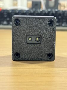
The DTOF Solid state LiDAR HM-LD1 is a compact solid-state dToF LiDAR module designed for real-time depth images and 3D point cloud data. It supports obstacle avoidance, distance detection, autonomous navigation, smart inspection, robotic vision development, UAV altitude hold, terrain following, autofocus, user presence detection, object recognition, volume measurement, and zone intrusion monitoring. With UART, UDP, and UVC interfaces, it can be integrated with PCs, Raspberry Pi systems, flight controllers, and embedded platforms for both prototyping and system deployment.
The product information describes HM-LD1 as useful for indoor or nighttime ranging up to 25 m and outdoor daytime ranging up to 8 m. It is designed for applications where compact size, lightweight construction, and direct depth output matter. The listed specification table gives dimensions of 43.5 mm × 30 mm × 26.5 mm, while the product description also references a compact housing value of 43.5 mm × 43.5 mm × 28.5 mm. Engineers should use the official mechanical drawing and current brochure during enclosure design, especially when mounting tolerances are tight.
View DTOF Solid state LiDAR HM-LD1
| DTOF Solid State LiDAR HM-LD1 Specifications | |
|---|---|
| Product Name | DTOF Solid state LiDAR HM-LD1 |
| Technology | Solid-state LiDAR based on SPAD dToF technology |
| Dimensions | 43.5 mm × 30 mm × 26.5 mm |
| Ranging Capability | Indoor: 0.5–25 m; Outdoor: 0.2–8 m |
| Ranging Accuracy | ±3 cm |
| Field of View | 60° horizontal × 45° vertical |
| Weight | 28 g |
| Resolution | 40 × 30 |
| Frame Rate | 10 fps |
| Interface | UART / UDP / UVC |
| Operating Temperature | -20 ℃ to 60 ℃ |
| Power Consumption | 1.2 W |
| Development Support | SDKs for x86 Windows, x86 Linux, and ARM Linux |
| Typical Applications | Obstacle avoidance, distance detection, autonomous navigation, smart inspection, robotic vision, UAV altitude hold, terrain following, SLAM, user presence detection, volume measurement, and zone intrusion monitoring |
View Product Details & Pricing ➔
Download the DTOF SSL HM-LD1 Product Brochure
What the Specs Mean for Engineers
The 28 g weight makes HM-LD1 attractive for drones, compact AMRs, inspection robots, and embedded devices where mass affects payload, energy use, or mechanical design. The 1.2 W power consumption supports battery-powered systems and small edge devices. The 60° horizontal × 45° vertical field of view can support forward-facing obstacle detection, localized depth awareness, inspection alignment, and UAV terrain following. The 10 fps frame rate can support many slow-to-moderate robot perception tasks, especially when the control strategy is designed around the sensor update rate and platform speed.
The UART, UDP, and UVC interfaces give developers flexibility. UVC can simplify PC-based visualization and rapid prototyping. UDP can support networked robotics systems and data streaming. UART can support embedded controller workflows where simpler distance or depth data is needed. SDK support for x86 Windows, x86 Linux, and ARM Linux helps teams move from desktop testing to embedded platforms such as Raspberry Pi-class systems or industrial Linux controllers.
Integration Workflow for Robots, UAVs, and Embedded Platforms
A LiDAR module only creates value when it is integrated into a complete sensing and control workflow. The Tesla Autopilot camera LiDAR test shows why perception cannot be judged by sensor hardware alone. Engineers must define the task, select the interface, calibrate mounting, process depth data, and validate behavior across the real operating domain. In the shop, the sensor is just one part of the machine. The mounting, software, logs, and control logic decide whether it actually helps.
Step 1 — Define the Perception Task
Start by defining whether the LiDAR will support obstacle avoidance, SLAM, altitude hold, terrain following, user detection, distance measurement, volume measurement, autofocus, or safety-zone monitoring. The task determines the required mounting position, field of view, range envelope, frame rate, processing pipeline, and acceptable latency. A drone doing terrain following may have different requirements from an AMR detecting pallets in an aisle or an inspection robot maintaining standoff distance from a wall.
Step 2 — Select the Data Interface
Interface selection should match the development stage and final system architecture. UVC is often useful for quick visualization and PC-based development. UDP can fit network-based data streaming, robotics middleware, and higher-throughput embedded systems. UART can be appropriate for embedded controllers and simpler distance-data workflows. The goal is to avoid choosing an interface only because it is convenient in the lab. It must also fit deployment, diagnostics, serviceability, and production constraints.
Step 3 — Calibrate Mounting and Coordinate Frames
Even a compact LiDAR must be mounted with known orientation and position relative to the robot body frame. Calibration matters for obstacle maps, SLAM, sensor fusion, and safe stopping distance calculations. If the LiDAR is tilted, offset, or mounted behind a protective window, those details must be included in the coordinate transform and validation plan. For robots using cameras, IMUs, wheel odometry, or GNSS, sensor alignment determines whether data fusion improves reliability or creates new errors.
Step 4 — Convert Depth into Robot Decisions
Raw depth is not enough. Engineers must filter noise, remove outliers, define valid regions of interest, compensate for mounting geometry, classify occupied space, and convert distance thresholds into actions. Those actions may include slowing down, stopping, avoiding, climbing, descending, triggering an alert, or requesting a higher-confidence mode. A future ROS LiDAR Integration Guide or Raspberry Pi Depth Sensor Project can help developers turn depth output into practical software workflows.
Step 5 — Validate Across the Real Operating Domain
A robot used indoors, outdoors, near sunlight, near reflective material, or in dusty industrial scenes should be tested in those exact conditions. The operating domain should be documented before deployment. UAV teams should test altitude hold and obstacle response near real terrain and real surfaces. Mobile robot teams should test aisles, ramps, people, pallets, glass, dark material, and forklifts. For aerial systems, an internal UAV Altitude Hold Sensor Guide would be a useful companion resource.
Engineering Validation Checklist
The most useful lesson from the Tesla Autopilot camera LiDAR test is that perception systems should be evaluated with disciplined validation. A robot should not be considered reliable simply because it worked once in a favorable scenario. Engineers need sensor-level, system-level, and scenario-level evidence. That means logs, repeat runs, measured distances, defined pass criteria, and enough uncomfortable testing to find weaknesses before customers do.
Sensor-Level Validation
- ✅ Measure range accuracy at known distances using calibrated targets.
- ✅ Confirm minimum and maximum usable distance for the actual installation.
- ✅ Test indoor, nighttime, outdoor, and high-lux daylight conditions.
- ✅ Measure performance on dark, bright, reflective, low-reflectance, and irregular targets.
- ✅ Map field-of-view coverage, blind zones, and mounting occlusions.
- ✅ Monitor frame rate stability and data consistency during long operation.
- ✅ Validate temperature behavior across the specified -20 ℃ to 60 ℃ range when relevant.
System-Level Validation
- ⚙️ Measure latency from sensing to control output.
- ⚙️ Calculate stop-distance margin at expected robot speeds.
- ⚙️ Record false positive and false negative events.
- ⚙️ Define behavior when depth data is missing, delayed, noisy, or uncertain.
- ⚙️ Evaluate interaction with cameras, IMU, wheel odometry, GNSS, visual SLAM, or other sensors.
- ⚙️ Test recovery after sensor dropout or communication interruption.
Scenario-Level Validation
- ✅ Pallet or box placed in an aisle.
- ✅ Person entering the robot path.
- ✅ Drone approaching a wall, tree, bridge surface, or industrial structure.
- ✅ Robot driving toward glass, dark material, or reflective surfaces.
- ✅ Outdoor sunlight tests at different times of day.
- ✅ Inclines, ramps, uneven terrain, vibration, and confined spaces.
- ✅ Repeated runs with logs saved for comparison and root-cause analysis.
For production deployment, connect this checklist to an internal Robot Safety Sensor Validation process so test data can support design reviews, customer acceptance, and lifecycle maintenance.
How to Choose a LiDAR Module for Industrial Robots
Choosing a LiDAR module is not about buying the longest range or the most expensive sensor by default. It is about matching the sensor to the robot’s working distance, speed, field of view, size, power budget, software environment, and safety requirement. The HM-LD1 specifications show how a compact dToF module can fit many embedded perception tasks, but engineers should still evaluate it against real use conditions. Datasheets are useful. Field data is better.
Match Range to Real Working Distance
Longer range is not always better if the robot mainly needs near-field obstacle detection. Engineers should match indoor and outdoor range to actual stopping distance, platform speed, mounting height, and operating environment. HM-LD1 lists indoor ranging from 0.5 m to 25 m and outdoor ranging from 0.2 m to 8 m. Those values help define where the module is suitable and where additional sensors, different mounting, or a different LiDAR class may be required.
Evaluate FOV Against Robot Geometry
A 60° horizontal × 45° vertical field of view may be suitable for forward depth awareness, localized obstacle detection, inspection alignment, user presence detection, or UAV terrain following. However, wide-area safety coverage may require multiple sensors, different mounting angles, or a complementary sensing layer. Engineers should simulate the field of view in the robot’s mechanical design before finalizing mounting.
Consider Weight, Power, and Thermal Conditions
The 28 g weight and 1.2 W power consumption are important for drones, battery-powered robots, and compact embedded systems. Operating temperature from -20 ℃ to 60 ℃ supports many industrial environments, but the complete product design still matters. Enclosures, protective windows, dust, airflow, heat sources, and vibration can all affect performance. Buyers should test the complete assembly rather than only the bare sensor.
Confirm Interface and SDK Support
Hardware is only useful if software integration is realistic. Support for UART, UDP, and UVC gives teams options across embedded controllers, networked systems, and PC-based development. SDKs for x86 Windows, x86 Linux, and ARM Linux reduce development friction for prototypes and embedded deployment. Before mass production, teams should confirm driver stability, data format, timestamp handling, logging, diagnostics, and long-duration operation.
Ask for Real-World Test Data
Before committing to a perception module, buyers should test their own target materials, lighting conditions, mounting geometry, platform vibration, and operating speeds. Record depth maps, point clouds, logs, confidence values, and control decisions. The best purchasing decision is not based only on a data sheet. It is based on data that matches the real operating domain.
Explore HM-LD1 for robot perception development
Conclusion
The Tesla Autopilot camera LiDAR test is valuable not because it settles a public debate, but because it reminds engineers to validate perception systems against uncertainty. Camera-only systems can be powerful because they interpret visual context, lane structure, object appearance, signs, and semantic meaning. However, they often infer depth from visual information. LiDAR provides direct depth measurement, helping robots understand where objects are in physical space.
For industrial autonomy, safer perception is built through sensor selection, test methodology, data logging, operating-domain definition, calibration, and fail-safe behavior. A compact dToF solid-state LiDAR such as DTOF Solid state LiDAR HM-LD1 can support depth maps, point clouds, obstacle avoidance, navigation, UAV altitude hold, smart inspection, and embedded perception development. The correct engineering approach is to test the module against real targets, real lighting, real speed, and real mounting constraints before deployment.
If your robot, UAV, inspection platform, or embedded vision product needs compact depth sensing, review the DTOF Solid state LiDAR HM-LD1 and evaluate its depth map, point cloud, range, interface, and SDK support against your real operating conditions.
Three Core Advantages — Elevating Perception Capability
FAQ
Does the Tesla Autopilot camera LiDAR test prove cameras are unsafe for autonomy?
Why did users argue about whether the Tesla test was fair or misleading?
When should robotics developers add LiDAR instead of relying only on cameras?
Is LiDAR better than a camera for robot obstacle avoidance?
What makes dToF LiDAR useful for compact robots and drones?
📚 References & Further Reading
- Industry Standard: Trimble | SOS LAB
- Related Guide: DTOF Solid state LiDAR HM-LD1 | DTOF SSL HM-LD1 Product Brochure






