RTK Receptor vs. Receiver: Centimeter-Precision GNSS Modules for Robotics & UAV Navigation
The demand for high-reliability spatial awareness has moved far beyond the limits of standard meter-level GPS. Modern unmanned aerial vehicles (UAVs), autonomous mobile robots (AMRs), and smart agricultural automation systems require centimeter-level absolute positioning accuracy to execute complex path-planning, precise spatial maneuvers, and repeatable mapping missions. At the core of this capability is Real-Time Kinematic (RTK) technology.
However, engineers, procurement leads, and developers sourcing high-precision positioning hardware often face linguistic and conceptual confusion. In web searches and international supply catalogs, the term “rtk receptor” frequently appears alongside “RTK receiver.” While “receptor” carries a distinct, highly documented biological definition—namely, Receptor Tyrosine Kinases involved in critical cellular signaling pathways—within the domains of global positioning, mechanical engineering, and localized logistics (particularly in Spanish, Portuguese, and French translation channels), a “receptor RTK” is simply an industrial-grade RTK receiver. This guide acts as a complete resource for clarifying these terminological crossovers, analyzing the mechanics of carrier-phase differential positioning, and presenting integration blueprints for embedding high-precision modules like the HM-D13 and HM-D20 into robotic and UAV platforms.
Table of Contents
- 👉 1. Demystifying the Terminology: RTK Receptor vs. RTK Receiver
- 👉 2. The Physics of Centimeter Precision: How RTK GNSS Operates
- 👉 3. Structural Analysis: Mushroom Dome vs. Helical Antennas in Robotics
- 👉 4. Deep-Dive Specification Analysis: HM-D13 vs. HM-D20
- 👉 5. Hardware Integration Guide: Configuring UART, PX4/Pixhawk, and ROS
- 👉 6. Optimizing RTK Links in Challenging Environments
- 👉 7. Industrial FAQ Section
1. Demystifying the Terminology: RTK Receptor vs. RTK Receiver
Navigating global supply chains for advanced robotics components can yield unexpected terminological rabbit holes. When engineering teams write technical specifications or search global databases for an “rtk receptor,” they are interacting with an interesting overlap between biochemistry and aerospace systems testing. Let’s clear the air and ensure your procurement paperwork is solid.
The Biological Definition of RTK Receptors
In human physiology, molecular biology, and oncology research, RTKs stand for Receptor Tyrosine Kinases. These are highly complex cell surface receptors that respond to external polypeptide growth factors, cytokines, and hormone molecules. Out of the vast genetic map of the human genome, researchers have categorized exactly 90 unique tyrosine kinase genes, 58 of which encode dedicated receptor tyrosine kinase proteins. These cell receptors feature an extracellular ligand-binding domain, a transmembrane anchor, and an intracellular tyrosine kinase domain. Upon ligand binding, they undergo dimerization, triggering autophosphorylation of their tyrosine residues, which in turn coordinates complex downstream cellular communication, managing cell growth, tissue repair, and metabolism. Unless you are building an organic wetware computing system, this has nothing to do with guiding a drone.
The Engineering Definition of RTK Receivers
In global industrial engineering and autonomous platform design, an “rtk receptor” refers to a Real-Time Kinematic Receiver. In Spanish, French, and Portuguese translations, the word for an electronic receiving device is direct: “receptor” or “récepteur.” Thus, if you are working with a field crew in South America or West Africa, or a logistics specialist in Spain looking for a “receptor RTK de alta precisión,” they are simply seeking a multi-band carrier-phase electronic processing module for satellite geodesy. The system lacks biological enzymes and instead relies on high-frequency reference oscillators, low-noise amplifiers, and digital signal processors to compute ultra-precise coordinates in real time.
An RTK receiver processes raw GNSS satellite signals and correlates them with correction streams sent from a known baseline position. By executing complex carrier-phase estimations, it removes the atmospheric errors that degrade standard GPS coordinates, allowing autonomous vehicles to navigate down to the millimeter. For engineers, regardless of the localized naming, the performance requirements remain standard: tracking multi-constellation satellite bands (GPS, BeiDou, GLONASS, Galileo, QZSS, and IRNSS) with minimum phase lock loops, high update frequencies, and reliable carrier-to-noise ratios.
2. The Physics of Centimeter Precision: How RTK GNSS Operates
Standard GNSS positioning is fundamentally limited. To understand why a standard receiver leaves you with three meters of horizontal uncertainty, we have to evaluate the path of radio frequency (RF) signals moving from orbits to the earth’s surface. Standard GNSS receivers compute distance via code-phase pseudorange estimation. The receiver estimates the transit time of the signal by correlating the satellite’s Pseudo-Random Noise (PRN) code with an identical local code generated inside the receiver’s processor. Because the fundamental “chipping” rate of standard codes is around 1.023 MHz, each code cycle has a physical length of approximately 293 meters. Even with advanced interpolation techniques, resolving these code shapes leaves several decimeters of basic measurement error. In the field, that means your agricultural drone will easily drift onto the wrong crop row.
RTK technology circumvents code limitations by measuring the carrier wave itself. The L1 carrier frequency operates at 1575.42 MHz, which corresponds to a physical wavelength of just 19 centimeters. The L5 carrier frequency operates at 1176.45 MHz, giving a wavelength of approximately 25 centimeters. By measuring the fractional phase of these sub-decimeter wavelengths, an RTK engine computes relative distances down to the millimeter range. It is a massive leap in precision, but it introduces a major mathematical challenge.
The receiver can measure the fractional phase of the arriving wave, but it cannot directly determine the integer number of full wave cycles between the satellite and the antenna. This is known as Integer Ambiguity ($\mathbf{N}$). To solve this integer ambiguity ($\mathbf{N}$), the system uses double-differencing mathematical algorithms. By subtracting measurements collected from two distinct satellites at two independent receivers—one fixed base station at a known position and one mobile unit (the “rover”)—common-mode systemic errors are canceled out. These include:
- ⚙️ Satellite clock bias and drift
- ⚙️ Receiver clock offsets
- ⚙️ Ionospheric delay profiles
- ⚙️ Tropospheric propagation delays
The resulting calculation yields a highly precise relative vector between the base and the rover. When dual-frequency or multi-band signals are processed concurrently (such as combining L1, L2, and L5 frequencies), these algorithms resolve the integer ambiguity almost instantly. This process is called Time-to-First-Fix (TTFF) or RTK convergence.
In demanding robotics environments, centimeter-level positioning is rarely used in isolation. To bridge the gap during temporary GNSS signal loss, autonomous platforms frequently fuse high-rate RTK navigation arrays with active optical perception systems, including LiDAR technology from Luminar Technologies and solid-state scanning arrays from SOS LAB. This multi-sensor approach ensures robust, continuous spatial awareness, even in complex indoor-outdoor transition zones.
3. Structural Analysis: Mushroom Dome vs. Helical Antennas in Robotics
In high-precision applications, the antenna is not just a passive collector; it acts as the primary spatial filter for incoming signals. Selecting the correct antenna geometry directly affects multipath rejection, phase center stability, and system performance during dynamic movements. On the bench, physical geometry dictates real-world performance.
Mushroom Dome Antennas (Patch/Dome Design)
Mushroom dome antennas use a horizontal, microstrip ceramic patch element protected by an aerodynamic, waterproof composite dome. These designs are highly flat and rely on a metal ground plane beneath the active element to isolate the receiver from reflected ground waves (multipath).
The structural pros & cons of mushroom dome antennas include:
- ✅ Highly Stable Phase Center Offset (PCO): The geographic center of the signal phase does not shift with changes in satellite elevation or azimuth.
- ✅ Superior Ground Multipath Rejection: The integrated ground plane naturally attenuates reflections coming from below the vehicle.
- ❌ High Mass and Profile: These systems are relatively heavy (often weighing over 400g), which can impact the payload capacity of smaller aerial platforms.
- ❌ Poor Low-Elevation Reception: Gain drops significantly as satellites approach the horizon.
This structural consistency makes mushroom dome antennas ideal for ground-based vehicles, precision agricultural machinery, and permanent base station setups where physical pitch and roll angles remain relatively low.
Helical Antennas (Quad-Filar Helix Design)
Helical antennas utilize a series of four copper resonant elements wrapped vertically around a cylindrical core. This configuration creates a highly sensitive, omnidirectional reception pattern that operates efficiently without requiring a localized ground plane.
The structural characteristics of helical antennas include:
- ✅ Excellent Low-Elevation Gain: They maintain signal tracking even when the vehicle tilts away from the zenith.
- ✅ Ultra-Lightweight and Compact Form Factor: Typically weighing under 40g, making them highly suited for payload-sensitive UAVs.
- ✅ No Ground Plane Required: Simplifies mounting on modular robotic masts and carbon-fiber drone arms.
- ❌ Susceptibility to Low-Angle Multipath: The omnidirectional design is more vulnerable to reflections from surrounding structures or water bodies.
A major benefit of helical antennas is their ability to maintain high signal gain during dynamic flights. When a multi-rotor UAV performs radical banking maneuvers or experiences strong wind gusts, a standard flat patch antenna tilts away from the satellite constellation, causing a sudden drop in signal quality and potential loss of the RTK lock. In contrast, a helical antenna captures clean signals down to and below the horizon, ensuring stable communication links during dynamic flights.
4. Deep-Dive Specification Analysis: HM-D13 vs. HM-D20
Integrating high-performance positioning hardware requires a thorough review of electrical, physical, and signal tracking specifications. The tables and technical overviews below showcase two professional-grade RTK modules designed for industrial robotics and UAV platforms.
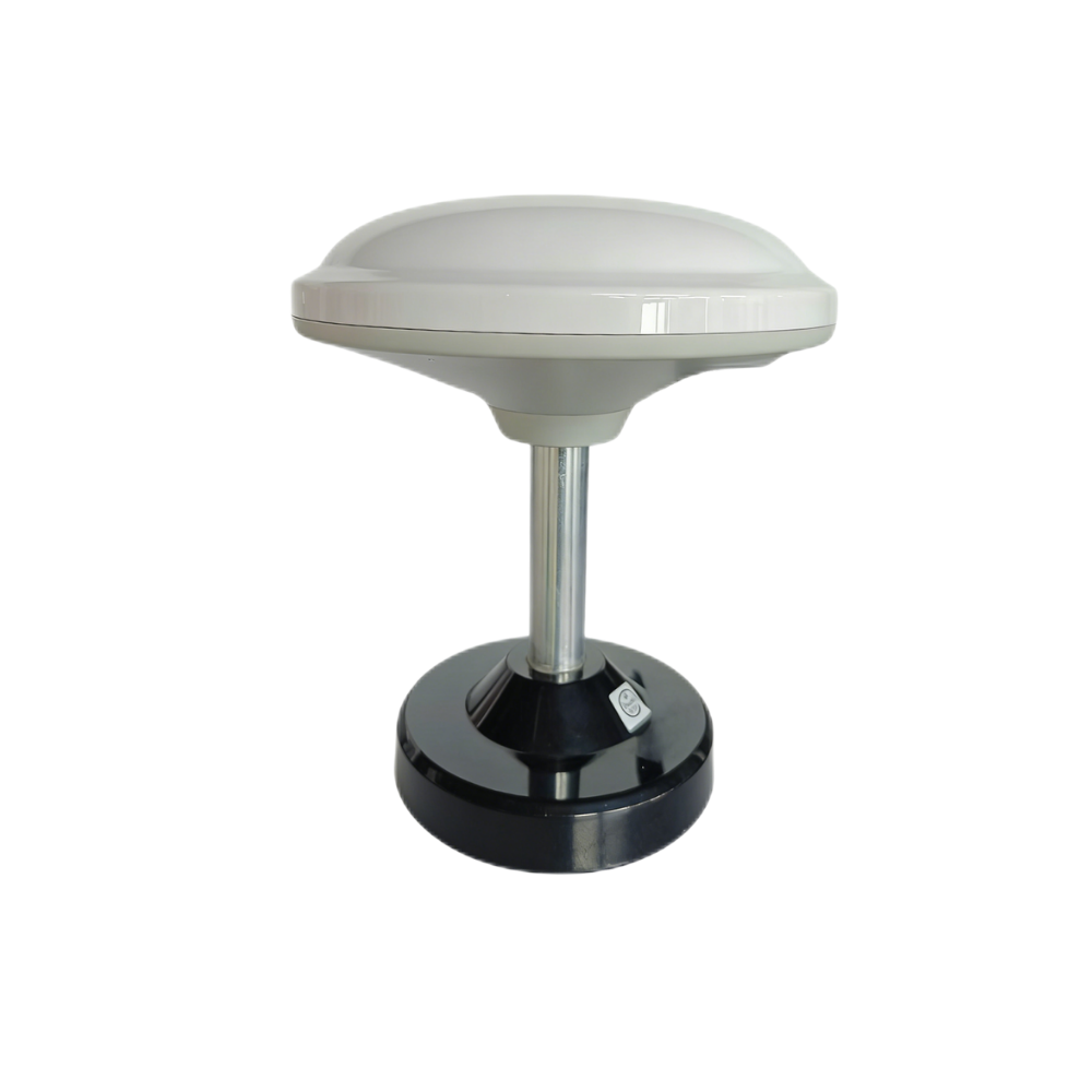
Product 1: Multiband RTK Survey Module HM-D13
An all-in-one mushroom-dome RTK receiver engineered for robust ground-system surveying, heavy machinery planning, and reference base station deployment.
| Specification Metric | Performance & Interface Standard |
|---|---|
| Frequency Band | GPS L1/L5, Beidou B1/B2A/B2I, Galileo E1/E5, QZSS L1/L5, GLONASS G1, IRNSS |
| RTK Position Accuracy | Horizontal: 1cm + 1ppm, Vertical: 1.5cm + 1ppm |
| Protocol Support | NMEA 0183 output and RTCM input at rover side. RTCM output at base side. |
| Baud Rate | 115200 bps |
| Dimensions | Φ152 * 67.9 mm |
| Weight | < 550 g |
| Interface | TTL level UART interface |
| Timing Synchronization | 20ns accuracy |
| Operating Temperature | -40 ℃ to 85 ℃ |
| Expansion Integration | Supports 4G radio module (optional for long-range corrections) |
Integrator Review: In the shop, we ran the HM-D13 through its paces. The module combines multi-system tracking with an integrated patch-dome elements array. Its UV-resistant polycarbonate (PC) housing resists discoloration and structural degradation during extended outdoor exposures, protecting internal elements from hard rain, wind forces, and extreme temperatures. This is your go-to hardware for base station deployments or heavy ground rovers.
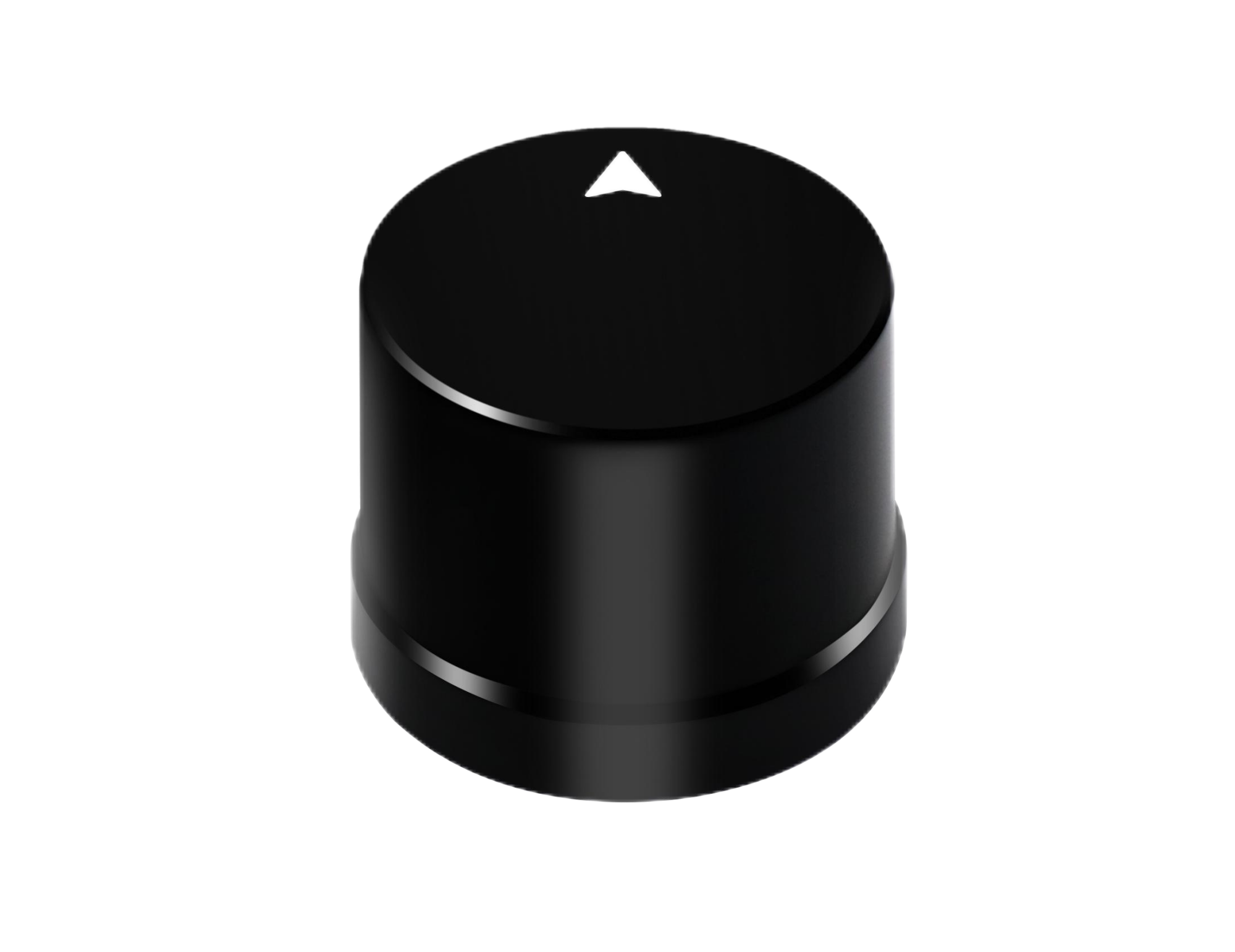
Product 2: Helical Antenna RTK Module HM-D20
An ultra-lightweight, quad-filar helical RTK module designed for critical payload-sensitive UAV fleets, autonomous marine surveying, and high-dynamic robotics.
| Specification Metric | Performance & Interface Standard |
|---|---|
| Frequency Band | GPS L1/L5, BeiDou B1/B2A/B2I, GLONASS G1, Galileo E1/E5, QZSS L1/L5, IRNSS L5 |
| RTK Position Accuracy | Horizontal: 1cm + 1ppm, Vertical: 1.5cm + 1ppm |
| Protocol Support | NMEA 0183 output and RTCM input at rover side |
| Baud Rate | 115200 bps |
| Dimensions | Φ44 * 37 mm |
| Antenna System LNA | At least 40dB high-gain system |
| Interface | TTL level UART interface |
| Timing Synchronization | 20ns accuracy |
| Operating Temperature | -40 ℃ to 85 ℃ |
| Waterproof Ingress IP | IP67 Certified |
Integrator Review: Look at the weight class here. The HM-D20 features an integrated dual-band helical GNSS antenna coupled with a sensitive onboard LNA. This design delivers a minimum of 40dB gain while eliminating the need for bulky ground planes. It is highly suited for unmanned surface vessels (USVs), lightweight logistics drones, and robotic platforms that require IP67 ingress protection for wet or harsh environments.
5. Hardware Integration Guide: Configuring UART, PX4/Pixhawk, and ROS
Connecting the HM-D13 or HM-D20 into your autopilot system or onboard computer requires attention to matching physical and software properties. Let’s walk through the exact setup procedures to get these modules running without frying your host system.
Physical Serial Hardware Interfaces
Both modules utilize Transistor-Transistor Logic (TTL) level UART serial interfaces operating on 3.3V logic levels. Do not connect these pins directly to old x86 RS232 levels (which can swing up to -12V to +12V) unless you want to watch your hardware release its magic smoke. For embedded processors without dedicated 3.3V serial ports, a reliable USB-to-TTL interface (such as an FTDI FT232RL or CP2102) is required to ensure clean signal routing.
| Wire Interface Code | Host Controller Connection Target | Electrical Specifications |
|---|---|---|
| VCC | System 5V DC Supply Bus | 4.75V to 5.25V DC; peak power spikes can occur during startup |
| TXD (Transmit) | Host Receiver UART RX Pin | 3.3V high logic levels; sends continuous NMEA/UBX state streams |
| RXD (Receive) | Host Transmit UART TX Pin | 3.3V input tolerance; accepts raw RTCM v3 correction streams |
| GND | System Common Ground bus | 0V reference level; keep return loops as short as possible to prevent ground loops |
Integration with PX4 / Pixhawk Flight Controllers
To connect either the HM-D13 or HM-D20 to an open-source flight stack like PX4 or ArduPilot, use the provided GPS interface cable to attach the module to the autopilot’s port labeled GPS1 or GPS2.
After making the physical connection, hook your flight controller up to your ground station PC via USB, launch your ground control software (such as QGroundControl), and configure the following parameters in the firmware parameter editor:
- ⚙️ GPS_1_CONFIG: Select the target UART port (typically set to GPS1 or TELEM4 configurations).
- ⚙️ SER_GPS1_BAUD: Set this value to 115200, matching the native transmission rate of our HM RTK modules.
- ⚙️ GPS_1_PROTOCOL: Configure to 1 (Auto-detect protocol framework) or force to 2 (specifically parsing UBX binary messages if available).
Once parameters are updated, reboot the vehicle. When you connect a compatible ground-based RTK antenna base station—or establish a connection to a local NTRIP network caster through your ground control software—the RTCM correctors are automatically injected over the standard MAVLink telemetry stream. This allows the vehicle’s navigation filter to transition from a standard 3D position lock to a centimeter-level RTK fix.
Software Integration with ROS / ROS2
For robotic platforms running on the Robot Operating System (ROS/ROS2), parsing serial data streams and converting them into standardized coordinate messages operates via serial processing nodes. Below is a production-grade Python-based parser script for ROS2 that reads standard NMEA GNGGA strings from the serial bus and publishes them as coordinate messages with standard coordinate covariances.
import rclpy
from rclpy.node import Node
from sensor_msgs.msg import NavSatFix, NavSatStatus
import serial

class NMEARTKParser(Node):
    def __init__(self):
        super().__init__('nmea_rtk_parser_node')
        self.declare_parameter('port_path', '/dev/ttyUSB0')
        self.declare_parameter('baud', 115200)

        serial_port = self.get_parameter('port_path').get_parameter_value().string_value
        baud_rate = self.get_parameter('baud').get_parameter_value().integer_value

        self.coordinates_publisher = self.create_publisher(NavSatFix, '/rtk/global_fix', 10)

        try:
            self.serial_link = serial.Serial(serial_port, baud_rate, timeout=1.0)
            self.get_logger().info(f"Successfully opened serial port: {serial_port}")
        except Exception as e:
            self.get_logger().error(f"Failed to open port {serial_port}: {str(e)}")
            raise e

        self.execution_timer = self.create_timer(0.05, self.read_serial_data_stream)

    def read_serial_data_stream(self):
        if self.serial_link.in_waiting > 0:
            try:
                line_data = self.serial_link.readline().decode('ascii', errors='ignore').strip()
                if line_data.startswith('$GNGGA') or line_data.startswith('$GPGGA'):
                    self.parse_gga_sentence(line_data)
            except Exception as error:
                self.get_logger().warn(f"Serial stream read warning: {str(error)}")

    def parse_gga_sentence(self, data_string):
        elements = data_string.split(',')
        if len(elements) < 10 or not elements[2] or not elements[4]:
            return # Skip if message lacks valid coordinates

        try:
            # Parse latitude degrees and minutes
            raw_lat = float(elements[2])
            lat_degrees = int(raw_lat / 100)
            lat_minutes = raw_lat - (lat_degrees * 100)
            latitude = lat_degrees + (lat_minutes / 60.0)
            if elements[3] == 'S':
                latitude = -latitude

            # Parse longitude degrees and minutes
            raw_lon = float(elements[4])
            lon_degrees = int(raw_lon / 100)
            lon_minutes = raw_lon - (lon_degrees * 100)
            longitude = lon_degrees + (lon_minutes / 60.0)
            if elements[5] == 'W':
                longitude = -longitude

            fix_status = int(elements[6])
            altitude_value = float(elements[9])

            msg = NavSatFix()
            msg.header.stamp = self.get_clock().now().to_msg()
            msg.header.frame_id = "rtk_receiver_frame"
            msg.latitude = latitude
            msg.longitude = longitude
            msg.altitude = altitude_value

            # Map NMEA fix quality to ROS status fields
            if fix_status == 4:  # RTK Fix
                msg.status.status = NavSatStatus.STATUS_GBAS_FIX
                msg.position_covariance = [0.0001, 0.0, 0.0, 0.0, 0.0001, 0.0, 0.0, 0.0, 0.0002]
            elif fix_status == 5:  # RTK Float
                msg.status.status = NavSatStatus.STATUS_FIX
                msg.position_covariance = [0.09, 0.0, 0.0, 0.0, 0.09, 0.0, 0.0, 0.0, 0.16]
            else:  # Standard GNSS Fix
                msg.status.status = NavSatStatus.STATUS_FIX
                msg.position_covariance = [2.25, 0.0, 0.0, 0.0, 2.25, 0.0, 0.0, 0.0, 4.0]

            msg.position_covariance_type = NavSatFix.COVARIANCE_TYPE_DIAGONAL_KNOWN
            self.coordinates_publisher.publish(msg)

        except ValueError as parse_error:
            self.get_logger().warn(f"Error parsing numerical values: {str(parse_error)}")

def main(args=None):
    rclpy.init(args=args)
    parser_node = NMEARTKParser()
    rclpy.spin(parser_node)
    parser_node.destroy_node()
    rclpy.shutdown()

if __name__ == '__main__':
    main()
6. Optimizing RTK Links in Challenging Environments
Operating high-precision GNSS hardware in real-world scenarios introduces physical challenges like concrete structures, dense tree canopies, and high electromagnetic noise. Let’s look at how to maintain a stable RTK fix in these conditions.
Managing Multipath Reflections
Multipath interference occurs when GNSS radio frequency waves bounce off vertical reflective structures—such as metal fences, shipping containers, and glass building facades—before reaching the antenna element. When direct and delayed reflected waves combine at the antenna, it can cause phase shifts that lead to “cycle slips.” These slips make it difficult for the receiver to resolve the integer ambiguity, forcing the system out of “RTK Fix” and back into “RTK Float” status, which increases positioning errors.
To reduce multipath and interference issues on ground-based rovers, we recommend installing a physical, conductive aluminum or carbon-fiber ground plate directly below patch elements like the HM-D13. For structural layouts where ground plates cannot be easily integrated, such as agile drone platforms, using high-gain helical modules like the HM-D20 is a good alternative. The helical element’s vertical multi-helix pattern naturally filters out reflected signals received at low angles, helping to maintain a continuous, high-quality satellite lock.
Enhancing Signal Penetration Through Canopies
Thick vegetative canopies present challenges for high-precision GNSS signals. Heavy foliage can absorb and scatter standard single L1-band signals. The HM-D13 and HM-D20 modules help address this by leveraging dual-band L1 + L5 frequency processing.
Here’s how dual-band signal processing saves your navigation accuracy under canopies:
- ✅ Multipath Separation: Signal streams from the L5 band have lower cross-correlation properties, which helps the receiver separate real direct signals from canopy reflections.
- ✅ Atmospheric Modeling: By comparing L1 and L5 phase delays, the receiver calculates ionospheric delays on-the-fly, reducing convergence time.
- ✅ Long-Wavelength Penetration: The longer L5 wave (25.4 cm) passes more effectively through damp leaves and branches without suffering the severe scattering that impacts the shorter L1 signal.
7. Industrial FAQ Section
What is the practical difference between an ‘RTK Receptor’ and an ‘RTK Receiver’?
In molecular biology, however, Receptor Tyrosine Kinases (RTKs) describe a large class of cell surface membranes. While there are exactly 90 unique tyrosine kinase genes, 58 of which encode dedicated cellular receptor tyrosine kinase proteins that coordinate cell growth and signal cascades via ligand-dependent dimerization, they have no relation to satellite geopositioning.
When engineering, drone, and surveying teams discuss an RTK receptor, they are referring to a multi-band carrier-phase electronic processor such as the HM-D13, designed to track satellite waveforms and apply correction data to achieve centimeter-level positioning accuracy.
How do I resolve constant RTK signal drops under heavy tree canopies?
The L5 band’s longer wave (25.4 cm) passes more effectively through damp canopies than the higher-frequency L1 signal. Additionally, using a high-gain helical module like the HM-D20 helps maintain signal locks without requiring a ground plane, making it easier to mount in optimal positions on UAV or robotic frames to avoid electromagnetic interference from motors and other onboard electronics.
What communication interfaces are used to connect these RTK modules to flight controllers?
To connect to modern processing platforms (such as an NVIDIA Jetson or a Raspberry Pi), use a USB-to-TTL converter to match the correct electrical levels. The module outputs standard NMEA-0183 sentences, including GNGGA, GNRMC, and GNGSA, and accepts RTCM v3 formatting for real-time correction injection.
Is a localized base station required to use these modules in RTK mode?
However, if your system operates in remote areas without cellular coverage, you will need a dual-receiver setup. In this configuration, one module (like the HM-D13) is placed at a fixed position to act as a base station and transmit correction data. A second module (such as the HM-D20) is mounted on the moving platform as a rover to process the corrections in real time.
How do physical temperatures and environmental factors impact RTK coordinate drift?
To protect against wet and dusty conditions, the HM-D20 is IP67 certified, while the HM-D13 features a rugged, UV-resistant polycarbonate housing. These features help ensure stable operations under challenging real-world conditions like rain, sand storms, or extreme direct sunlight.
📚 References & Further Reading
- Industry Standard: Luminar Technologies Sensor Integration Design Principles
- Related Guide: SOS LAB Solid-State LIDAR and GNSS Multi-Agent Alignment