


LiDAR Sensors for Drones: Lightweight 3D Perception for Obstacle Avoidance
Here’s the deal: when a drone is flying near trees, buildings, equipment, power lines, or uneven terrain, a few meters can separate a successful autonomous mission from a damaged aircraft. Cameras provide valuable visual detail, but they do not measure distance directly. Changing light, low-texture walls, motion blur, dust, shadows, and hard backlighting can all make image-based depth estimation less dependable. That is why many UAV developers are adding LiDAR sensors for drones to obtain direct, real-time measurements for obstacle avoidance, terrain following, altitude hold, inspection, landing assistance, and autonomous navigation.
The engineering challenge is straightforward, even if the solution is not: the sensor has to deliver useful 3D perception without using too much payload capacity, electrical power, or onboard processing. The HM-LD1 is a compact solid-state direct Time-of-Flight, or dToF, LiDAR built for robots, drones, and embedded autonomous systems. It weighs 28 g, consumes approximately 1.2 W, provides 40 × 30 depth resolution, and supports indoor ranging from 0.5–25 m plus outdoor ranging from 0.2–8 m at up to 80 klux. This guide covers how drone LiDAR works, which specifications matter in the field, where the technology fits, and how to evaluate the HM-LD1 for a practical UAV perception architecture.
Table of Contents
- 👉 Why Drones Need LiDAR for 3D Perception
- 👉 How LiDAR Sensors for Drones Work
- 👉 dToF LiDAR Compared with Other Drone Sensors
- 👉 Key Specifications for UAV LiDAR Selection
- 👉 HM-LD1 Product Specifications for Drone Perception
- 👉 Drone Applications and Use Cases
- 👉 UAV Integration Guide
- 👉 Deployment Limitations and Test Planning
- 👉 Drone LiDAR Selection Checklist
- 👉 Frequently Asked Questions
Why Drones Need LiDAR for 3D Perception
A drone does not travel across a flat, predictable work surface. It changes altitude, pitch, roll, yaw, and velocity while passing trees, walls, roofs, cables, machinery, vehicles, terrain, and people. An autonomous UAV therefore needs more than a recognizable picture. It needs timely spatial information that tells its software where an obstacle is, how far away it is, and whether the current flight path is likely to intersect it.
Look, a conventional RGB camera records appearance rather than direct metric distance. Computer-vision software has to infer depth from stereo geometry, movement between frames, known object dimensions, focus, or trained machine-learning models. Those methods can work very well, but their performance depends on image texture, illumination, calibration, exposure, processing capacity, and vehicle motion. A blank warehouse wall, repeating roof pattern, harsh glare, deep shadow, or blurred frame can create trouble at exactly the wrong time.
LiDAR uses an active optical measurement method. The sensor emits light, evaluates the returned signal, and produces direct distance measurements that can be arranged as a depth map or point cloud. In the shop, that distinction matters. A camera can show that something looks like a steel beam; LiDAR can report that the surface is 2.7 meters ahead and slightly left of the vehicle centerline.
That metric depth can support a broad range of UAV functions:
- ✅ Forward collision warning and obstacle avoidance
- ✅ Side-facing proximity monitoring near walls, tanks, bridges, and structural assets
- ✅ Downward relative-altitude measurement
- ✅ Low-altitude terrain following
- ✅ Landing-zone evaluation and flare assistance
- ✅ Indoor navigation where GNSS reception is unavailable or unreliable
- ✅ Inspection near buildings, towers, machinery, and industrial equipment
- ✅ Robotic docking and charging-station alignment
- ✅ Near-field sensing during low-speed autonomous flight
One compact LiDAR module does not automatically provide complete environmental awareness. Coverage still depends on field of view, mounting angle, airframe obstructions, software-defined regions of interest, and the number of installed sensors. The HM-LD1 has a 60° horizontal by 45° vertical field of view. A forward-facing installation observes a directional volume ahead of the UAV. A downward-facing installation observes the ground or structure beneath it. Wider coverage, including near-360-degree protection, normally requires multiple modules or complementary sensing technologies.
The sensor also has to be connected to useful decision logic. Measuring an object at three meters does not tell the aircraft whether it should brake, climb, hover, reverse, or divert. That decision depends on speed, stopping distance, flight mode, available escape paths, measurement confidence, wind, controller authority, and total system latency. Engineers building an avoidance system should review how drones detect and avoid obstacles as part of the complete safety architecture rather than treating the LiDAR as a stand-alone fix.
How LiDAR Sensors for Drones Work
Direct Time-of-Flight Measurement
Direct Time-of-Flight LiDAR measures how long emitted light takes to travel to a surface and return. A light source sends a pulse or modulated optical signal into the environment. Part of that energy reflects from an object and comes back to the receiver. Because the speed of light is known, the sensor can calculate distance from the measured round-trip travel time.
The simplified relationship is d = (c × t) ÷ 2, where d is distance, c is the speed of light, and t is the measured round-trip time. The calculation is divided by two because the light travels out to the target and then back to the receiver.
- ⚙️ A VCSEL emits near-infrared illumination.
- ⚙️ The optical energy travels toward surfaces inside the sensor’s field of view.
- ⚙️ A portion of the emitted photons reflects from those surfaces.
- ⚙️ The receiver detects the returned optical energy.
- ⚙️ The sensor estimates distance from the measured travel time.
- ⚙️ The measurements are organized into a depth map or point-cloud output.
The HM-LD1 uses a 940 nm VCSEL and SPAD-based photon detection. SPAD stands for Single-Photon Avalanche Diode. This receiver technology is intended to detect weak optical returns, which matters when a target is distant, dark, narrow, angled, or relatively low in reflectivity. It does not eliminate the basic limits of optical sensing, but it gives the module a way to extract useful ranging information from returns that may be difficult to measure.
Depth Maps and Point Clouds
A depth map assigns a measured distance to each valid sensing location. Instead of showing the color and texture of a wall, it reports how far each sampled area of that wall is from the sensor. A point cloud takes those measurements and expresses them as three-dimensional positions. Depending on the application, those points can be represented in the LiDAR coordinate frame, the drone body frame, or a world and navigation frame after calibration and transformation.
The HM-LD1 provides 40 × 30 depth resolution at 10 frames per second. This is spatial-ranging output, not high-resolution photography. Software can inspect the complete depth frame or divide it into practical regions such as center, upper, lower, left, and right safety zones. Invalid, unstable, or low-confidence measurements can be filtered before persistent obstacles are passed to planning or flight-control logic.
A 10 fps sensor produces a new frame about every 100 milliseconds before interface, processing, communication, and controller delays are included. Whether that is fast enough depends on aircraft speed, obstacle dimensions, required stopping distance, and end-to-end latency. It can be suitable for many low- and moderate-speed proximity tasks, but no experienced integrator should assume that 10 fps is automatically adequate for every airframe.
For example, an aircraft traveling at 5 m/s moves roughly half a meter during a single 100-millisecond frame interval. Add filtering, network transmission, command generation, controller response, and the physical time needed to arrest forward motion, and the total distance becomes longer. That is why frame rate has to be evaluated as one piece of the response chain rather than a stand-alone performance number.
Why dToF Is Useful in Outdoor UAV Systems
Outdoor operation is demanding because solar illumination introduces substantial optical background energy. A drone can move from shade to direct sun, then into backlighting or reflected glare, in a matter of seconds. The HM-LD1 is specified for outdoor ranging from 0.2–8 m at up to 80 klux and indoor ranging from 0.5–25 m. Those conditions need to remain separate. The 25 m indoor figure should not be advertised or treated as a bright-daylight operating range.
Actual performance can vary with target reflectivity, target angle, surface geometry, sunlight direction, atmospheric conditions, installation quality, contamination on the optical window, and interference from other emitters. Published range figures are useful for shortlisting a sensor, but they do not replace representative testing.
Drone perception also sits inside a larger navigation system. Organizations such as Bynav Technology illustrate the broader positioning and navigation environment, while semiconductor suppliers such as onsemi provide useful background on imaging and sensing technology. These references offer industry context only. They do not imply certification, endorsement, or supply of the HM-LD1.
dToF LiDAR Compared with Other Drone Sensors
LiDAR Versus RGB Cameras
Cameras provide high-resolution color, texture, edges, and visual context. They are useful for recognizing people, vehicles, signs, vegetation, structural details, cracks, and landing markers. LiDAR answers a more geometric question: how far away is the observed surface? A camera may classify an object, while LiDAR measures whether that object has crossed into a warning, braking, or emergency zone.
Neither technology wins every job. A compact depth sensor provides less visual detail than an RGB camera, while a monocular camera does not inherently provide direct metric depth. In many UAV systems, the better answer is sensor fusion. Visual data contributes identity and context; LiDAR contributes measured range.
LiDAR Versus Stereo Vision
Stereo vision estimates depth by comparing the apparent displacement of features viewed by two calibrated cameras. It can produce detailed spatial information without active illumination, but it depends on visible features, stable calibration, suitable baseline geometry, and adequate image quality. Uniform walls, repeating patterns, poor illumination, overexposure, or motion blur can weaken stereo matching.
dToF LiDAR actively measures range and can continue working where visual texture is limited. Its constraints include finite range, target reflectivity, spatial resolution, ambient light, and field of view. The correct choice comes from the actual mission scene, not from a single headline specification.
LiDAR Versus Ultrasonic Sensors
Ultrasonic sensors are generally economical and can be useful for short-range proximity or altitude measurement. Their sound-based operation may be affected by wind, target angle, soft materials, acoustic interference, propeller wash, and rotor-generated airflow. Many ultrasonic devices also return one limited beam measurement rather than a structured depth image.
LiDAR uses optical ranging and can provide multiple measurements across a two-dimensional field of view. That spatial structure helps software determine whether the closest obstacle is centered, above, below, or off to one side of the current flight path.
LiDAR Versus Radar
Radar can offer longer-range detection and dependable operation in certain lighting and weather conditions. LiDAR often provides finer near-field spatial detail, although the result depends heavily on the classes of sensors being compared. Radar modules vary widely in mass, antenna configuration, range, angular resolution, power consumption, update rate, and processing requirements.
A fast outdoor UAV may need more warning distance than a compact short-range LiDAR can provide. A small indoor aircraft, on the other hand, may care more about low mass, low power, and useful near-field geometry. Mission speed and stopping distance should drive the selection.
LiDAR and Sensor Fusion
A practical UAV architecture may combine several sensing methods:
- ✅ An IMU for acceleration and angular-rate measurement
- ✅ GNSS for global outdoor position
- ✅ A barometer for pressure-based altitude estimation
- ✅ Cameras for visual context, classification, and inspection
- ✅ LiDAR for direct metric depth
- ✅ A flight controller for stabilization and command execution
- ✅ A companion computer for synchronization, filtering, mapping, and planning
Look, more sensors do not automatically make a safer aircraft. The measurements need valid timestamps, known coordinate frames, sensible confidence handling, and defined failure behavior. A companion computer may synchronize the inputs, transform measurements, reject noise, and generate planning or safety requests, but the complete chain still has to be tested under real flight conditions.
Developers who are new to the terminology can review what LiDAR stands for. Teams comparing active optical methods can also explore structured-light 3D vision. Structured light and dToF LiDAR are both active depth technologies, but they use different measurement principles and can behave differently in range, ambient light, resolution, and target conditions.
Key Specifications for UAV LiDAR Selection
Weight and Physical Dimensions
Every installed component affects payload margin, battery endurance, center of gravity, mounting stiffness, and vibration response. The HM-LD1 weighs 28 g, excluding any application-specific bracket, cable, regulator, enclosure, weather seal, or companion computer. Its controlled specification-table dimensions are 43.5 mm × 30 mm × 26.5 mm.
One descriptive passage on the technical product page contains a conflicting size statement of 43.5 mm × 43.5 mm × 28.5 mm. Because the formal source specification table lists 43.5 mm × 30 mm × 26.5 mm, that table value is used in this guide. Before machining a bracket or releasing an enclosure drawing, production engineers should confirm the current mechanical drawing with the supplier. In the shop, fixing a dimension conflict before fabrication is cheap. Fixing it after tooling is not.
Range and Accuracy
The HM-LD1 is specified for 0.5–25 m indoors and 0.2–8 m outdoors at up to 80 klux. Its stated ranging accuracy is ±3 cm. Accuracy describes the stated relationship between reported distance and actual distance under applicable conditions. It does not mean every target, material, angle, light level, or installation will produce identical results.
Operational range also has to fit the aircraft dynamics. A sensor that detects an obstacle at eight meters may be appropriate for a slow inspection drone but inadequate for a faster platform with a longer braking and maneuvering distance. Engineers should distinguish between maximum reported range and dependable warning range for the specific target set.
Field of View and Resolution
The 60° horizontal × 45° vertical field of view defines the angular observation region. The 40 × 30 resolution defines the spatial sampling grid within that region. As distance increases, each sample covers a larger physical area. Small, narrow, or thin objects may therefore be difficult to detect, especially near the edge of the field of view.
Mounting orientation should follow the job. A forward-facing installation can support frontal obstacle sensing. A downward-facing module can measure terrain clearance. Side-mounted sensors can help during close-proximity inspection. Several calibrated modules may be required when the aircraft needs broader coverage.
Frame Rate and End-to-End Latency
The listed frame rate is 10 fps, but frame rate is only one part of system response. Engineers need to evaluate acquisition delay, interface transmission, buffering, timestamp handling, filtering, perception processing, flight-controller communication, actuator response, wind, and aircraft inertia. The useful calculation is how far the UAV travels during the complete detect-decide-act cycle.
A bench demonstration may show a stable depth image while hiding several layers of latency. Data may sit in a buffer, wait for a network cycle, pass through a perception node, and then wait again for the flight controller. Measure the complete path with timestamps. Do not estimate it from the sensor frame rate alone.
Power and Thermal Behavior
The HM-LD1 consumes approximately 1.2 W and has a listed operating-temperature range of -20 °C to 60 °C. UAV designers should include that load in the full electrical budget and account for regulator efficiency, connector losses, onboard-computer power, and thermal behavior inside the finished enclosure. Direct sunlight and weak airflow can push internal temperatures above ambient conditions.
Power quality matters too. A nominally adequate supply can still produce startup drops, ripple, or transient noise when motors change speed. The sensor should be tested on the actual aircraft power architecture rather than only on a clean laboratory supply.
Interfaces and Software Compatibility
UART, UDP, and UVC provide several integration paths. UART supports serial embedded communication. UDP can move data through a networked onboard architecture. UVC can connect the module to a compatible USB host. Product information also identifies SDK availability for x86 Windows, x86 Linux, and ARM Linux, along with development compatibility for Raspberry Pi, NVIDIA Jetson, and ROS/ROS2-oriented systems.
The interface choice affects more than wiring. It can change available bandwidth, driver complexity, latency, connector retention, electromagnetic compatibility, and fault handling. Verify the exact protocol and electrical requirements before committing the flight hardware.
HM-LD1 Product Specifications for Drone Perception
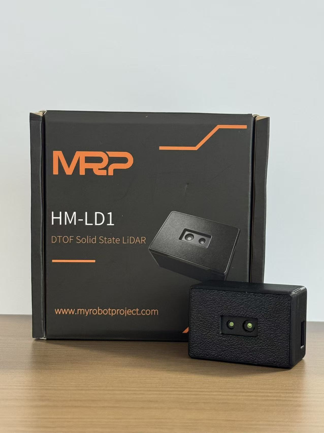
The HM-LD1 is an all-in-one solid-state 3D dToF LiDAR intended for robots, UAVs, and autonomous machines that need compact depth perception. It produces real-time depth-map and point-cloud information for obstacle detection, navigation assistance, distance measurement, and embedded perception. Its 28 g mass and approximately 1.2 W consumption are particularly relevant to payload-sensitive aircraft.
Those numbers make the module worth evaluating, but they should not be viewed in isolation. The final installed system includes wiring, mounting hardware, environmental protection, power conversion, and whatever processor handles the depth data. That complete package is the number that belongs in the aircraft mass and endurance model.
HM-LD1 Compact 3D dToF LiDAR for Robot and Drone Perception

This cased HM-LD1 module combines a 940 nm VCSEL, SPAD-based dToF sensing, depth processing, and UART, UDP, and UVC connectivity. It is designed to deliver structured depth rather than identifiable RGB images, which can also support privacy-conscious presence and movement applications. Class 1 eye-safety compliance is identified in the supplied product description for the 940 nm VCSEL illumination.
| Specification | HM-LD1 |
|---|---|
| Technology | Solid-state direct Time-of-Flight 3D LiDAR |
| Resolution | 40 × 30 |
| Indoor ranging capability | 0.5–25 m |
| Outdoor ranging capability | 0.2–8 m at up to 80 klux sunlight |
| Ranging accuracy | ±3 cm |
| Field of view | 60° horizontal × 45° vertical |
| Weight | 28 g |
| Dimensions | 43.5 mm × 30 mm × 26.5 mm |
| Wavelength and emitter | 940 nm VCSEL |
| Frame rate | 10 fps |
| Interfaces | UART, UDP, UVC |
| Operating temperature | -20 °C to 60 °C |
| Power consumption | Approximately 1.2 W |
| Output | Depth-map and point-cloud ranging data |
View Product Details & Pricing ➔
DTOF Solid-State LiDAR HM-LD1 Technical Product Listing
The technical HM-LD1 listing focuses on embedded integration and multi-scenario development. It describes SPAD dToF operation, real-time depth images and 3D point clouds, outdoor daytime ranging, compact construction, and support for obstacle avoidance, autonomous navigation, distance detection, smart inspection, robotic vision, UAV altitude hold, and terrain following.
The listing also identifies development support across x86 Windows, x86 Linux, and ARM Linux. UART, UDP, and UVC connectivity enables integration with computers, Raspberry Pi platforms, flight-control architectures, and other embedded hosts, subject to protocol and electrical verification.
| Area | Provided Product Information |
|---|---|
| Desktop SDK environments | x86 Windows and x86 Linux |
| Embedded SDK environment | ARM Linux |
| Development platforms | Raspberry Pi and NVIDIA Jetson compatibility identified |
| Robotics development | ROS/ROS2-oriented development support identified |
| UAV functions | Obstacle avoidance, altitude hold, and terrain-following development |
| Other stated applications | Robot navigation, SLAM, autofocus, presence detection, object recognition, volume measurement, and zone intrusion monitoring |
Drone Applications and Use Cases
Forward Obstacle Avoidance
A forward-facing HM-LD1 can monitor the volume ahead of a drone and send depth measurements to an avoidance algorithm. Software may divide the field of view into caution, braking, and emergency regions. It can also require an obstacle to remain present across several frames before issuing a maneuver, which helps reduce unnecessary reactions to isolated invalid samples.
Thresholds must match speed. A warning distance that works for a slow indoor quadrotor may be unsuitable for a faster outdoor aircraft. Engineers should account for processing latency, communication delay, controller response, wind, braking authority, minimum obstacle dimensions, and the availability of a safe escape direction.
Here’s the practical point: obstacle detection and obstacle avoidance are not the same function. Detection reports the geometry. Avoidance decides what to do with it. The aircraft still needs flight-envelope limits, command arbitration, and a predictable response if no safe path is available.
Altitude Hold and Terrain Following
Mounted downward, the module can measure relative distance to a surface and contribute to altitude-hold or terrain-following logic. A region-based method can track the nearest valid surface or calculate a more stable representative terrain distance. LiDAR data may be fused with barometric, inertial, GNSS, or visual information instead of being used as the only altitude source.
Slopes, foliage, water, glass, dust, and rapidly changing aircraft attitude can affect measurement geometry. If the drone rolls or pitches, line-of-sight distance is not automatically the same as vertical altitude. Body attitude, sensor orientation, and the local surface normal should be considered in the transformation.
Indoor Autonomous Flight
The listed indoor range of 0.5–25 m can support operation near walls, shelving, machinery, corridors, and structural elements. Indoor environments remove direct sunlight from many applications, but they bring their own problems, including reflective floors, windows, narrow aisles, dust, and several surfaces appearing at different ranges within one field of view.
Because the HM-LD1 supplies depth rather than RGB imagery, it can support geometry-based navigation without depending on identifiable visual images. A complete indoor autonomy system will still need localization, route planning, mapping, control, and fail-safe landing behavior.
Agricultural and Environmental Drones
Low-altitude agricultural aircraft can use near-field depth sensing to detect trees, equipment, terrain changes, fence posts, and other structures. A downward-facing sensor may help maintain clearance as ground height changes. A forward-facing module can contribute obstacle measurements inside its stated range and field of view.
LiDAR does not identify crop species, nutrient status, disease, or plant health by itself. Those jobs generally require RGB, multispectral, thermal, or other specialized instruments. The HM-LD1 contributes geometric distance perception, which can complement those payloads.
Inspection and Infrastructure Missions
Inspection UAVs often work near bridges, buildings, dams, industrial equipment, storage tanks, and other assets that are difficult or unsafe for people to approach. Compact LiDAR can help maintain stand-off distance and monitor nearby structures. For bright outdoor work, the stated 0.2–8 m range at up to 80 klux needs to be respected. Missions requiring longer stand-off distances may require another LiDAR class.
In close inspection, sensor placement matters as much as sensor selection. A module mounted behind landing gear, a camera gimbal, or a protective rail may have part of its field of view blocked. Model the coverage and then verify it on the assembled aircraft.
Privacy-Preserving Human Sensing
Depth-based data can support presence detection, movement tracking, gesture recognition, and spatial interaction without recording conventional RGB images. This may reduce dependence on identifiable imagery in human-centered applications. It should not be described as guaranteed anonymity, though. Depth and movement data can still reveal behavioral or spatial information and must be managed under applicable privacy, security, and data-governance requirements.
UAV Integration Guide
Mechanical Mounting
The mount has to hold the sensor rigidly enough to preserve calibration while limiting harmful vibration. The optical aperture needs a clear view, and the airframe, landing gear, payload, wiring, or propellers should not enter the intended sensing region. Engineers should evaluate propeller wash, debris, dust accumulation, cable strain, center-of-gravity changes, and environmental protection.
Orientation must be measured, not guessed. Even a small angular installation error creates a larger position offset as range increases. Record the LiDAR translation and rotation relative to the UAV body frame and apply that transform in software. If multiple modules are installed, calibrate each one to a shared frame.
In the shop, use a repeatable locating feature instead of relying only on friction and visual alignment. If a module can rotate slightly after a hard landing or maintenance event, the software may still process data while using an outdated calibration. Mechanical witness marks and scheduled alignment checks can help catch that problem.
Electrical Integration
Provide a stable regulated supply and include the approximately 1.2 W sensor load in the complete power budget. Verify startup behavior, grounding, connector retention, wire gauge, cable routing, voltage tolerance, and electrical-noise control. The calculation should include conversion losses and processing hardware, not just the LiDAR’s nominal consumption.
Motor controllers, radios, and high-current power wiring can introduce noise. Keep signal wiring away from noisy conductors where practical, use appropriate grounding, and test the sensor while propulsion loads are changing. A system that behaves perfectly with the motors stopped has not completed electrical validation.
Data Integration
UART can support a direct serial connection to an embedded processor. UDP can be used when the aircraft has a networked companion-computer architecture. UVC can connect to a compatible USB host. Before choosing an interface, confirm voltage levels, packet formats, bandwidth, driver support, timestamps, error states, cable limits, and SDK compatibility.
Initial integration should display raw depth data without controlling the aircraft. The next stages should validate frame timing, invalid measurements, coordinate direction, field-of-view alignment, and distance against calibrated references. Autonomous commands should be enabled only after the data path is understood.
Companion Computers and Development Platforms
Product information identifies Raspberry Pi, NVIDIA Jetson, Windows x86, Linux x86, and ARM Linux support. A Raspberry Pi may be appropriate for interface development and relatively light depth processing. A Jetson platform may make sense when LiDAR is fused with neural-network inference, visual processing, mapping, or more demanding planning workloads. ROS and ROS2-oriented development can help organize messages and coordinate frames, provided timestamps and transforms are handled correctly.
Do not select the companion computer on processor capability alone. Include memory use, storage, boot time, connector availability, operating temperature, power draw, software maintenance, and recovery after an application fault. An onboard computer that takes too long to restart may not fit the aircraft’s safety concept.
Conceptual Obstacle-Avoidance Logic
- ⚙️ Acquire a timestamped depth frame.
- ⚙️ Identify invalid, out-of-range, unstable, or low-confidence measurements.
- ⚙️ Transform valid points from the sensor frame into the UAV body frame.
- ⚙️ Divide the observed volume into mission-specific safety zones.
- ⚙️ Estimate obstacle distance, location, size, and persistence.
- ⚙️ Account for aircraft velocity, heading, attitude, wind, and stopping distance.
- ⚙️ Generate a warning, speed reduction, hover, or avoidance request.
- ⚙️ Apply a defined fail-safe response if valid depth data becomes unavailable.
The HM-LD1 is a perception component, not a complete autonomous-flight safety system. The aircraft manufacturer or integrator remains responsible for control logic, redundancy, validation, operational limits, maintenance requirements, and regulatory compliance.
Evaluate HM-LD1 for Your Drone Perception System
Review the module specifications and discuss interface compatibility, mounting orientation, development platform, environmental conditions, and required perception range before committing to a production architecture.
Deployment Limitations and Test Planning
Published specifications are useful screening criteria, but they cannot reproduce every combination of target material, installation, weather, lighting, motion, and control behavior. Whenever possible, testing should use the actual airframe, power system, processor, enclosure, interface, and software.
A representative test program should include:
- ✅ Bright sunlight up to the intended operating illumination
- ✅ Sunlight entering from different directions and angles
- ✅ Dark and low-reflectivity targets
- ✅ White and highly reflective surfaces
- ✅ Angled, curved, and irregular surfaces
- ✅ Thin obstacles, cables, branches, and vegetation
- ✅ Glass, water, mirrors, and polished materials
- ✅ Dust, fog, and light rain where mission-relevant
- ✅ Propeller vibration and rapid attitude changes
- ✅ Electrical noise and high processor loading
- ✅ Temperature extremes within the intended mission profile
- ✅ Multiple nearby active optical sensors
- ✅ Partial contamination of the optical window
- ✅ Temporary data loss and interface interruptions
Metrics should include detection probability, false-positive rate, range error, frame-to-frame stability, invalid-data rate, end-to-end latency, dropped-frame frequency, warning distance, controller response time, and successful avoidance rate. Thin wires deserve special attention because their apparent size may be small relative to the sensor’s spatial sampling at distance.
Developers should test stationary and moving scenarios. Bench measurements confirm range and repeatability, but flight testing reveals vibration, airflow, changing attitude, sun angle, communication delay, and control interaction. Early flight tests should use low speed, generous separation, safety pilots, and conservative fallback behavior.
Test failure modes deliberately. Disconnect the data link, block part of the optical aperture, overload the processor, and inject stale or invalid measurements in a controlled environment. The objective is to confirm that the aircraft responds predictably rather than continuing under a false assumption that the perception data is current.
The stated HM-LD1 outdoor capability is 0.2–8 m at up to 80 klux, while its indoor capability is 0.5–25 m. These figures are not universal guarantees across every material and geometry. Final operating limits should come from measured performance in the intended application.
Drone LiDAR Selection Checklist
UAV manufacturers and system integrators can use this checklist when evaluating the HM-LD1 or comparing it with other LiDAR sensors for drones:
- ✅ Is the 28 g module weight compatible with the complete payload budget?
- ✅ Have the bracket, cable, regulator, enclosure, and processor also been included?
- ✅ Does the stated range match UAV speed and worst-case stopping distance?
- ✅ Is outdoor performance specified at a relevant ambient-light level?
- ✅ Is a 60° horizontal × 45° vertical FOV appropriate for the mounting location?
- ✅ Can 40 × 30 resolution detect the expected obstacle dimensions?
- ✅ Is 10 fps compatible with total system latency and control requirements?
- ✅ Is ±3 cm stated accuracy appropriate for the measurement task?
- ✅ Can the power system continuously support approximately 1.2 W plus conversion losses?
- ✅ Does the mission remain within the listed -20 °C to 60 °C operating range?
- ✅ Is UART, UDP, or UVC compatible with the selected architecture?
- ✅ Is the required SDK available for Windows, Linux, or ARM Linux?
- ✅ Can the development team integrate with Raspberry Pi, NVIDIA Jetson, ROS, or ROS2 as required?
- ✅ Can the module be mounted with an unobstructed optical aperture?
- ✅ Has coordinate-frame calibration been planned and documented?
- ✅ Have sunlight, dark surfaces, angled targets, vegetation, glass, and water been tested?
- ✅ Is one directional field of view sufficient, or are multiple sensors required?
- ✅ Is there a defined fallback if LiDAR data becomes invalid, stale, or unavailable?
- ✅ Have product dimensions been confirmed against the current mechanical drawing?
- ✅ Can the supplier provide integration support for the intended application?
The HM-LD1 combines low mass, modest power demand, real-time depth output, several interfaces, and specified bright-outdoor ranging in one compact solid-state module. Its suitability still depends on aircraft dynamics and mission conditions. Review the HM-LD1 product details and download the technical brochure before prototype integration.
Request Your Trial Sample (Exclusive Discount Code Included)
Are you developing the next generation of autonomous mobile robots (AMRs), delivery drones,or smart automation systems? Whether you are a fast-growing startup, an established engineering firm, or leading a specialized robotics project, finding high-precision sensors that fit your budget shouldn’t be your biggest hurdle.
At MyRobotProject.com, we believe exceptional perception technology should be accessible to projects of every size. To help you accelerate your prototype development and field testing,we are opening an exclusive discount program for first-time sample orders of our dTOF Solid-State Lidar Sensors.
Why Choose Our dTOF Solid-State Lidar?
Direct Time-of-Flight (dTOF) solid-state technology offers the reliability, speed, and precision needed for high-performance spatial awareness without the mechanical wear-and-tear of traditional rotating Lidar sensors.
Decent Quality Under Budget: Premium-grade performance engineered to respect your Bill of Materials (BOM) constraints.
Solid-State Reliability: Built for long service life, shock resistance, and demanding operational environments.
Versatile Applications: Ideal for obstacle avoidance, precision hovering, mapping, and micro-navigation in robotics and drone platforms.
Claim Your First-Trial Sample Order Discount
We want to empower your development cycle right from day one. If you are ordering your very first trial sample, we are offering an exclusive online introductory discount tailored to your project scope.
How to Apply:
Send an Email to [email protected]
Include the Following Details:
Your Company / Firm Name (or Project Name)
Your Estimated Project Quantity / Target Volume
Mention that this is your very first trial order
Include Promo Code: MRP-202607 in your subject line or email body.
Fast-Track Guarantee: Our technical sales team will review your project details and respond with your customized discount quote in less than 24 hours.
Ready to Build?
Don’t let budget constraints slow down your technical validation. Reach out today with code MRP-202607 and let’s bring your robot or drone project to life!
Frequently Asked Questions About LiDAR Sensors for Drones
Can LiDAR Sensors for Drones Work Reliably in Bright Sunlight?
Will a LiDAR Sensor Add Too Much Weight or Power Consumption to My UAV?
How Difficult Is It to Integrate the Sensor with a Flight Controller or Onboard Computer?
What Is the Difference Between a Drone LiDAR Sensor and a Conventional Laser Rangefinder?
Is the HM-LD1 Suitable for Altitude Hold and Terrain Following?
Can One HM-LD1 Sensor Provide 360-Degree Obstacle Detection?
What Interfaces Does the HM-LD1 Support?
What Development Platforms Are Compatible with the HM-LD1?
Is LiDAR Better Than a Camera for Drone Obstacle Avoidance?
📚 References & Further Reading
- Industry Standard: Bynav Technology navigation and positioning resources
- Industry Standard: onsemi sensing and semiconductor resources
- Related Guide: How Drones Detect and Avoid Obstacles
- Related Guide: What Does LiDAR Stand For?
- Related Guide: Structured-Light Precision 3D Vision
- Product Resource: DTOF SSL HM-LD1 Product Brochure






