


What Does LiDAR Stand For? A Practical Guide to LiDAR Meaning, Accuracy, and Robotics Applications
LiDAR stands for Light Detection and Ranging. Here’s the deal: it is a sensing technology that uses light, usually laser light, to detect objects, measure distance, and build useful spatial information about the world around a machine. A LiDAR sensor sends light toward a target, catches the reflected signal, and calculates how far away that target is. That simple idea is why LiDAR has become so valuable in robotics, drones, industrial automation, mapping, inspection systems, smart cameras, and embedded machine vision projects.
Look, LiDAR is not just something bolted onto high-end autonomous cars anymore. Modern compact solid-state dToF LiDAR modules have made depth sensing practical for autonomous mobile robots, UAVs, Raspberry Pi development, ROS and OpenCV projects, obstacle avoidance, altitude hold, SLAM, safety monitoring, and industrial distance measurement. This guide explains what LiDAR means, how it works, how accurate it can be, how it compares with cameras and radar, and how a real module such as the DTOF Solid State LiDAR HM-LD1 fits into practical robotics and UAV applications.
Table of Contents
- 👉 What Does LiDAR Stand For?
- 👉 LiDAR Meaning in Practical Engineering
- 👉 How LiDAR Works: Laser Pulses, Time-of-Flight, and Point Clouds
- 👉 Main Types of LiDAR Sensors
- 👉 LiDAR vs Camera, Radar, and Laser Scanning
- 👉 How Accurate Is LiDAR?
- 👉 LiDAR Applications in Robotics, UAVs, and Industrial Automation
- 👉 Product Example: DTOF Solid State LiDAR HM-LD1
- 👉 How to Choose a LiDAR Module
- 👉 The Future of LiDAR in Robotics
- 👉 FAQ: LiDAR Meaning, Accuracy, and Robotics Applications
What Does LiDAR Stand For?
LiDAR stands for Light Detection and Ranging. The term describes both the source of the measurement and the job the system is doing. “Light” refers to the optical energy emitted by the sensor, usually laser light. “Detection” means the receiver identifies the light that reflects back from a surface. “Ranging” means the electronics calculate the distance between the sensor and the object based on that returned signal.
You may see the term written as LiDAR, LIDAR, lidar, or sometimes laser radar. In everyday engineering use, those spellings usually point to the same broad class of technology: an active optical sensing system that uses emitted light to measure distance. It is called active because it sends out its own signal. A normal camera depends mostly on ambient light and records appearance, color, contrast, and texture. A LiDAR sensor sends out optical energy and uses the reflection to produce measurable distance data.
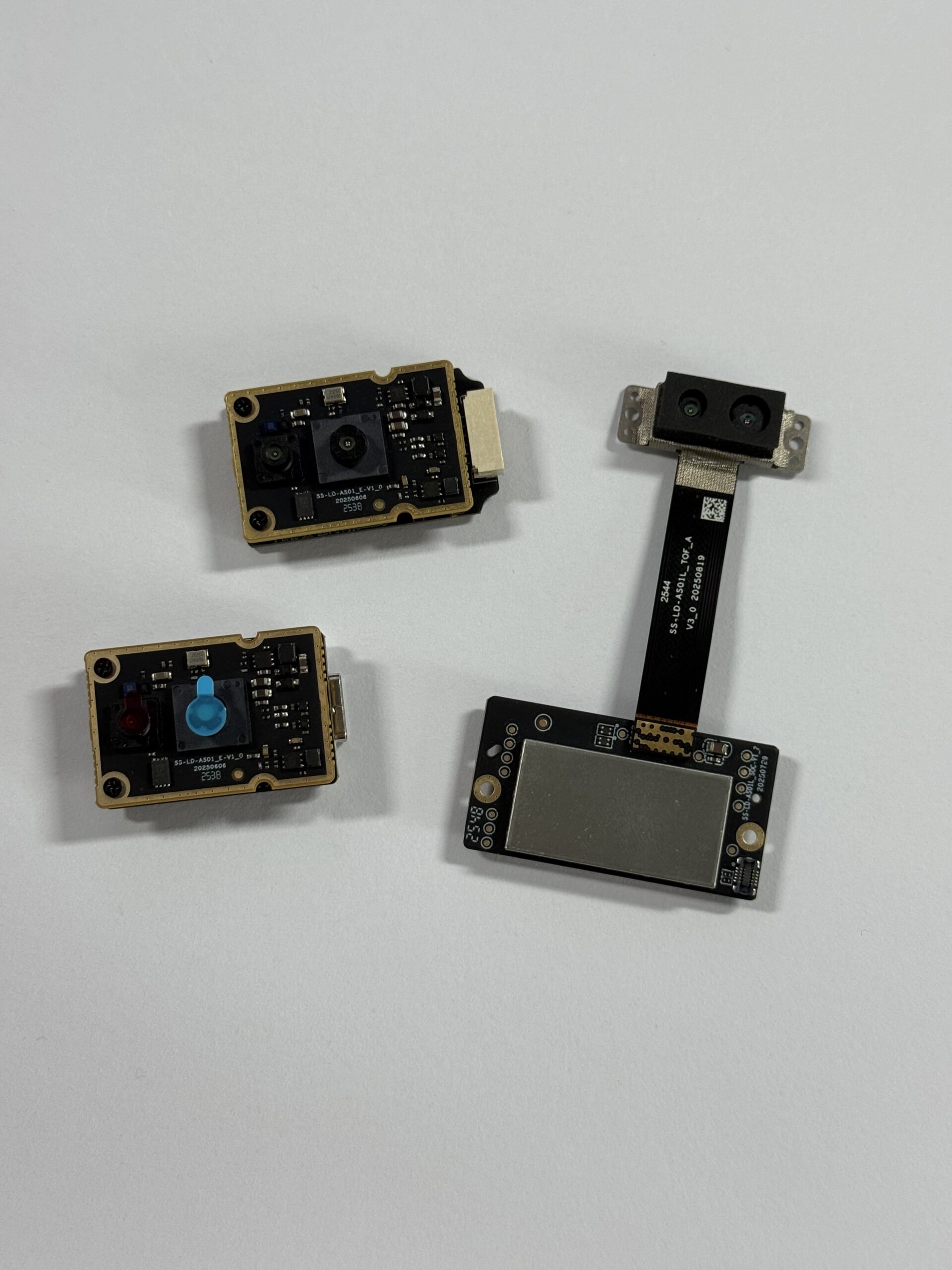
That distinction matters on the plant floor and in the field. A robot does not just need to know that something looks like an obstacle; it needs to know where that obstacle sits in space. A drone does not just need to see the ground; it may need to hold a reliable height above changing terrain. An inspection system does not just need a nice image of a bridge, wall, conveyor, or pallet; it may need distance information that can drive a real automation decision.
In the shop, that is where LiDAR earns its keep. It turns physical space into depth data that software can use. LiDAR is widely used in autonomous vehicles, warehouse automation, UAV navigation, infrastructure inspection, surveying, security systems, service robots, smart cameras, industrial measurement, and research platforms. Engineering teams comparing perception technologies often place LiDAR beside cameras, radar, ultrasonic sensors, structured light, and laser scanners. For additional perspective on industrial sensor ecosystems, you can also review resources from domisensor.
LiDAR Meaning in Practical Engineering
In practical engineering, LiDAR means a machine can understand distance and spatial structure in real time. Instead of working from a flat image only, the system receives measurable information about how far surfaces are from the sensor. That matters because motion is geometry. If a robot is moving through a warehouse, it has to understand walls, shelves, pallets, people, low obstacles, open aisles, loading zones, and objects that were not there ten seconds ago.
A UAV working close to the ground has a different problem, but the same need for spatial awareness. It needs height, terrain changes, nearby structures, and safe clearance. A smart security device may need to know whether a person entered a restricted zone, not just whether pixels changed in a video feed. LiDAR helps turn those situations into distance-based logic instead of guesswork.
LiDAR as Depth Sensing
Depth sensing is one of the most common practical meanings of LiDAR. A depth sensor provides distance values across part of a scene. Depending on the sensor design, the output may appear as a single distance value, a 2D scan, a depth image, or a 3D point cloud. A depth map is especially useful because it works like an image where each measurement point or pixel represents distance rather than color.
For embedded vision teams, that format is convenient. Software can detect object boundaries, free space, height differences, approach distance, and proximity zones without relying only on color or texture. In industrial automation, depth sensing supports pallet detection, bin monitoring, approach control, volume estimation, doorway detection, robot docking, and line-side safety monitoring. In UAV systems, it can support altitude hold, landing assistance, obstacle awareness, and terrain following.
✅ Practical benefit: depth data gives the control system a measurement it can act on.
✅ Engineering value: the machine can make decisions based on distance, not just appearance.
✅ Integration advantage: depth maps can often be processed with familiar computer vision tools.
LiDAR as 3D Perception
LiDAR also means 3D perception. When multiple distance measurements are organized into coordinates, the result can become a point cloud. A point cloud represents visible surfaces as points in three-dimensional space. This is useful for mapping, localization, collision avoidance, object sizing, robotic navigation, and environmental modeling. In SLAM, which means simultaneous localization and mapping, LiDAR data can help a robot build a map while estimating its own position inside that map.
Point clouds can be combined with camera images, IMU data, wheel odometry, GNSS, UWB positioning, and AI models. The camera may help classify what an object is, while LiDAR helps measure where that object is. The IMU helps estimate motion, while LiDAR helps correct position against surrounding geometry. Good sensor fusion is not about collecting more data for the sake of it. It is about combining the right data so the machine makes a better decision.
LiDAR as Machine Spatial Awareness
The most valuable meaning of LiDAR is machine spatial awareness. Humans naturally understand space by using vision, motion, body awareness, and experience. Machines need sensors and algorithms to approximate that ability. LiDAR gives a machine direct distance information, which improves its ability to plan movement, avoid collisions, maintain safe operating zones, and interpret the physical world.
This is especially helpful in places where visual texture is limited or lighting conditions change. A plain wall may be difficult for a camera-only system to interpret if it has few visible features. A LiDAR sensor can still measure distance to that wall if the reflected signal is strong enough for the sensor design. Likewise, a robot approaching a shelf, conveyor, doorway, or docking station benefits from measured distance instead of visual estimation alone.
How LiDAR Works: Laser Pulses, Time-of-Flight, and Point Clouds
LiDAR works by emitting light, receiving the reflected signal, and converting that signal into distance information. The exact method depends on the sensor architecture, but the basic workflow is consistent. First, the emitter sends laser light into the scene. Second, the light travels until it reaches an object or surface. Third, some of that light reflects back toward the sensor. Fourth, the receiver detects the returned light. Fifth, processing electronics calculate distance. Finally, software organizes those measurements into formats such as distance readings, depth maps, or point clouds.
For engineers, the important point is that LiDAR directly measures range rather than guessing depth from a visual image. The system uses physics-based timing or signal behavior to estimate distance. That is why LiDAR is so useful for robotics, UAVs, industrial inspection, and safety-related perception. It provides quantitative measurement data that can feed control systems, navigation stacks, mapping algorithms, and AI perception pipelines.
Time-of-Flight Principle
Time-of-flight is one of the core principles behind many LiDAR systems. In a time-of-flight sensor, the device measures how long it takes for emitted light to travel to a target and return to the receiver. Because the speed of light is known, the sensor can calculate distance from the travel time. The round-trip time must be divided by two because the light travels from the sensor to the object and then back again.
That sounds simple until you remember how fast light moves. Even tiny timing differences correspond to meaningful distance changes. A well-built LiDAR module has to combine an optical emitter, receiver, timing electronics, signal processing, calibration, and software output into one stable measurement system. In compact robotics modules, all of that is packaged into a small device that can be mounted on an embedded platform.
⚙️ Step one: emit controlled laser light into the target area.
⚙️ Step two: detect the returned optical signal from the surface.
⚙️ Step three: calculate distance from timing or signal behavior.
⚙️ Step four: output usable depth data for software and controls.
dToF vs iToF LiDAR
Two common time-of-flight approaches are dToF and iToF. dToF means direct time-of-flight. It measures the direct travel time of a light pulse from emission to return detection. iToF means indirect time-of-flight. It estimates distance by analyzing phase shift or modulation behavior rather than directly timing a single pulse in the same way. Both approaches can be useful, and the best choice depends on application requirements, target distance, size, power, cost, frame rate, and desired accuracy.
dToF is often attractive for applications that need reliable ranging and compact depth sensing. A module such as the DTOF Solid State LiDAR HM-LD1 is based on SPAD dToF technology and is designed to deliver real-time depth images and 3D point cloud data. That makes LiDAR practical for robot developers, UAV engineers, embedded Linux teams, and automation integrators who need a compact sensor rather than a large rotating scanner.
SPAD Sensors in Modern LiDAR
SPAD stands for Single-Photon Avalanche Diode. SPAD sensors are sensitive optical detectors that can detect very weak reflected light signals. In LiDAR systems, that sensitivity helps support compact modules and depth imaging designs. When paired with dToF measurement, SPAD technology can help produce depth data suitable for real-time perception tasks.
For industrial users, the underlying detector technology matters because it affects practical performance. Range, accuracy, ambient light tolerance, frame rate, power consumption, field of view, and physical size are all influenced by sensor architecture. A good LiDAR module is not only defined by its maximum range. It must provide usable output under the real constraints of the job, including sunlight, target reflectivity, vibration, mounting position, software integration, and power budget.
Depth Map vs 3D Point Cloud
A depth map is a two-dimensional data structure where each measurement point stores distance. It is similar to an image, except the value represents depth rather than color. Depth maps are convenient for embedded vision because they can be processed with image-like algorithms. They can support obstacle zone detection, object segmentation, presence sensing, autofocus, volume estimation, and simple navigation logic.
A 3D point cloud represents surfaces as coordinates in space. Point clouds are common in robotics, mapping, SLAM, surveying, inspection, and autonomous navigation. They provide geometry that can be used to estimate object shape, environmental layout, and robot position. Some LiDAR modules provide both depth image data and point cloud output, which gives engineers flexibility. A robotics engineer may use depth images for lightweight obstacle detection and point clouds for mapping or visualization.
Main Types of LiDAR Sensors
LiDAR is not a single sensor format. The term covers several architectures, each with strengths and limitations. When choosing a LiDAR module, engineers should consider range, field of view, resolution, frame rate, size, weight, power consumption, interface, operating environment, software support, and mechanical reliability.
Mechanical LiDAR
Mechanical LiDAR systems use moving parts, often rotating assemblies, to scan the environment. They can provide wide field-of-view coverage and dense spatial information, which is useful for mapping, autonomous vehicle prototypes, and some industrial applications. The trade-off is that mechanical systems are often larger, heavier, more expensive, and more mechanically complex than compact solid-state modules. Moving parts can also affect durability, integration options, and maintenance planning.
✅ Best fit: wide-area scanning and mapping where size and cost are acceptable.
⚙️ Watch point: moving parts may affect long-term reliability in harsh environments.
Solid-State LiDAR
Solid-state LiDAR is designed without large rotating mechanical assemblies. This makes it attractive for compact robots, drones, smart cameras, and embedded devices where size, reliability, and ease of integration matter. Solid-state modules can be mounted in front-facing, downward-facing, or application-specific positions to provide depth awareness over a defined field of view.
The DTOF Solid State LiDAR HM-LD1 belongs in this practical category. It is a compact dToF solid-state LiDAR module based on SPAD dToF technology and provides real-time depth images and 3D point cloud data. For embedded robotics, the advantage is not only the sensing principle but also the integration package: compact dimensions, low weight, low power consumption, and multiple interfaces.
Flash LiDAR
Flash LiDAR illuminates a scene and captures depth information over an array. Instead of scanning one point at a time across a large area, it can capture a depth image over its field of view. This approach can be useful for short-range and mid-range depth imaging, smart cameras, presence detection, and robotics perception. Depending on the implementation, flash LiDAR can provide compact depth sensing suitable for embedded systems.
Scanning LiDAR
Scanning LiDAR measures points sequentially using a scanning mechanism or optical scanning method. It may generate high-density maps and structured spatial data. Scanning architectures can be useful for mapping and profiling, but trade-offs may include frame rate, complexity, mechanical design, cost, and integration requirements. In many applications, the right choice depends on whether the system needs broad mapping coverage or focused real-time depth awareness.
Single-Point LiDAR
Single-point LiDAR measures one distance at a time. It can be useful for simple ranging, height detection, level measurement, proximity sensing, and presence detection. However, a single-point sensor does not provide full 3D perception unless it is mechanically scanned or combined with motion. For applications such as obstacle avoidance, SLAM, and object zone monitoring, a depth-imaging or multi-point LiDAR module may be more appropriate.
LiDAR vs Camera, Radar, and Laser Scanning
LiDAR is often compared with cameras, radar, and laser scanners because all of these technologies help machines sense the environment. They measure different physical properties and provide different kinds of information. A camera captures appearance. Radar uses radio waves to detect objects and velocity. LiDAR uses light to measure distance and geometry. Laser scanners may overlap with LiDAR, but some scanners provide only planar or single-line measurements depending on their design.
| Technology | What It Measures | Strengths | Limitations | Typical Uses |
|---|---|---|---|---|
| LiDAR | Distance and 3D depth using light | Accurate ranging, depth maps, point clouds, strong spatial awareness | Performance can vary with reflectivity, sunlight, fog, rain, and sensor design | Robotics, UAVs, SLAM, mapping, obstacle avoidance |
| Camera | Visual appearance, color, texture | Rich image detail, low cost, object recognition | Needs lighting, and depth is indirect unless stereo or depth-assisted | Inspection, AI vision, recognition, monitoring |
| Radar | Object presence, range, and velocity using radio waves | Works well in fog, dust, rain, and poor visibility | Often lower spatial resolution than LiDAR in short-range robotic perception | Vehicles, speed detection, industrial safety, outdoor sensing |
| Laser Scanner | Distance points using scanning laser measurement | High precision, structured scanning, mapping | May be single-plane or mechanically dependent depending on design | Surveying, profiling, industrial measurement |
LiDAR vs Camera
Cameras are excellent for visual recognition. They can capture color, texture, printed labels, signs, object features, surface defects, and human-readable visual information. AI vision systems often rely on cameras because images contain semantic detail. However, a standard monocular camera does not directly know distance. It can estimate depth using algorithms, stereo matching, motion, or AI models, but those estimates depend heavily on lighting, texture, calibration, and model assumptions.
LiDAR directly measures distance. It may not provide the same color detail as a camera, but it provides geometry. In many industrial systems, the best design combines both. The camera identifies what an object is, while LiDAR measures where it is. For example, an AMR can use a camera to recognize a pallet label and LiDAR to understand the pallet’s position relative to the robot.
LiDAR vs Radar
Radar uses radio waves rather than light. It is strong in fog, dust, rain, and poor visibility, and it can measure velocity effectively. This makes radar valuable in automotive, industrial safety, and outdoor sensing systems. However, radar typically provides lower spatial resolution than LiDAR in many short-range applications. It may detect that an object exists, but it may not describe fine geometry as precisely as a LiDAR depth image or point cloud.
LiDAR is often preferred where geometric detail is important. Robots navigating around shelves, walls, people, and equipment need accurate spatial boundaries. UAVs flying near structures may need reliable height and surface distance. Industrial inspection systems may need a clear measurement of object position. Radar and LiDAR can also be combined when the system must operate across a broader range of weather and visibility conditions.
LiDAR vs Laser Scanner
The terms LiDAR and laser scanner can overlap. Some laser scanners are LiDAR systems because they use laser light to measure distance. However, not every product described as a laser scanner provides the same type of data. Some industrial laser scanners measure a single line or plane. Others generate 3D spatial data. A 3D LiDAR module can provide richer depth representation when the application requires spatial perception over an area rather than a single measurement plane.
When comparing products, engineers should focus less on naming and more on output format, range, accuracy, FOV, resolution, frame rate, interface, and environmental performance. The practical question is not only “Is it LiDAR?” but “Does this sensor provide the right data for my robot, drone, inspection system, or embedded vision stack?”
How Accurate Is LiDAR?
LiDAR accuracy depends on sensor architecture, timing precision, calibration, range, target reflectivity, ambient light, weather, field of view, resolution, frame rate, mounting quality, and software processing. A high-quality sensor has to perform not just under ideal laboratory conditions but in the real environment where it will be deployed. For robotics and UAV applications, engineers should evaluate both the stated specification and the operating context.
Ranging Accuracy
Ranging accuracy describes how close the measured distance is to the real distance. For example, the DTOF Solid State LiDAR HM-LD1 lists a ranging accuracy of ±3 cm. This type of centimeter-level ranging can be useful for obstacle distance estimation, robotic navigation, altitude control, smart inspection, and zone detection. The required accuracy depends on the application. A safety warning zone may tolerate more error than a precise measurement task, while a drone landing system may need stable readings over a specific height range.
Range and Environment
Indoor and outdoor LiDAR performance can differ significantly. Sunlight introduces strong ambient optical energy that can make detection more difficult. Target reflectivity also matters. Bright, reflective surfaces may return stronger signals, while dark, absorbent, angled, or transparent surfaces may be more challenging. Fog, rain, dust, and smoke can also affect optical sensing.
The HM-LD1 provides an indoor ranging capability of 0.5–25 m and an outdoor ranging capability of 0.2–8 m. Product information notes accurate ranging even from a long distance of 8 meters on a clear summer day, assuming approximately 80,000 lux. This makes the module useful for distance measurement to objects that may be difficult or unsafe for people to approach, including bridges, expressways, dams, and other inspection targets.
Resolution and Frame Rate
Resolution determines how many depth samples are captured across the field of view. A higher resolution can provide more detailed shape information, while a lower resolution may still be sufficient for obstacle awareness, zone detection, or lightweight embedded perception. Frame rate determines how often the data updates. Faster systems can support quicker movement and more responsive control, while moderate frame rates may be suitable for slower robots, static monitoring, or inspection tasks.
The HM-LD1 has a resolution of 40 × 30 and a frame rate of 10 fps. This combination is appropriate for compact depth sensing applications where low weight, low power, and real-time environmental awareness are more important than extremely high-density mapping. For many embedded robotics systems, a stable and easily integrated depth stream is more valuable than excessive data volume that overloads the processor.
Field of View
Field of view controls how much of the scene the sensor can observe. A wider field of view helps detect objects across a larger area, while a narrower field may be preferred for targeted ranging. Front-facing robots often need enough horizontal and vertical coverage to detect low obstacles, hanging objects, shelf edges, people, and open pathways. UAVs may use downward-facing or forward-facing LiDAR depending on whether the goal is altitude hold, terrain following, landing assistance, or obstacle detection.
The HM-LD1 provides a field of view of 60° horizontal × 45° vertical. This gives a practical coverage area for near-field robotics, smart cameras, UAV sensing, presence detection, and object zone monitoring. The right mounting angle and processing logic are important because even a capable sensor must be positioned correctly to observe the region that matters.
LiDAR Applications in Robotics, UAVs, and Industrial Automation
LiDAR is widely used because many automation problems are really spatial problems. Machines need to know how far away objects are, where free space exists, how surfaces are arranged, and whether the environment has changed. Compact dToF LiDAR modules bring this ability into smaller systems where traditional large LiDAR units may be too heavy, expensive, or mechanically complex.
AMR Obstacle Avoidance
Autonomous mobile robots operate in dynamic environments. They may encounter people, carts, pallets, shelves, doors, walls, cables, packaging, and unexpected objects. LiDAR supports obstacle avoidance by providing distance information that can be converted into warning zones, speed reduction zones, or stop commands. Depth maps can help identify free space in front of the robot, while point cloud data can provide geometry for more advanced navigation systems.
SLAM and Navigation
SLAM means simultaneous localization and mapping. A robot using SLAM builds a map of its environment while estimating its own position inside that map. LiDAR supports SLAM because it provides measurable geometric features such as walls, corners, obstacles, shelves, and structural boundaries. The data can be combined with wheel odometry, IMU readings, cameras, GNSS, or UWB positioning to improve robustness.
UAV Altitude Hold and Terrain Following
Drones need reliable height information for low-altitude flight, landing assistance, and terrain following. Barometers and GNSS can help in some scenarios, but LiDAR provides direct distance to surfaces below or ahead of the UAV. A lightweight sensor is especially important because payload affects flight time, stability, and battery life. Compact modules such as the HM-LD1 can support UAV altitude hold and terrain following where weight and power budget are limited.
Inspection and Distance Measurement
Infrastructure inspection often involves locations that are difficult, costly, or unsafe for people to approach. Bridges, expressways, dams, industrial facilities, storage areas, and large structures may require distance measurement from a safe platform. LiDAR can support measurement and inspection by providing range data from a robot, drone, or fixed monitoring system. Outdoor performance should always be evaluated against lighting, target material, angle, and expected distance.
Smart Cameras and Security Zones
LiDAR can improve smart cameras and security systems by adding depth awareness. Instead of only detecting changes in image pixels, a system can estimate whether an object entered a specific distance zone. This is useful for user presence detection, zone intrusion monitoring, object recognition support, volume measurement, autofocus, and privacy-conscious spatial sensing. Depth-based detection can help reduce false alarms when lighting changes or when visual appearance alone is unreliable.
Embedded Development with Raspberry Pi, ROS, and OpenCV
For developers, interfaces and software support are as important as optical specifications. The HM-LD1 supports UART, UDP, and UVC interfaces, enabling integration with embedded controllers, networked data systems, and camera-like depth streaming workflows. MRP also offers SDKs for x86 Windows, x86 Linux, and ARM Linux, supporting development across PCs, Raspberry Pi platforms, embedded Linux devices, and robotics computers.
This flexibility helps engineering teams prototype quickly and move toward deployment. A developer might use UVC for convenient depth stream access, UDP for networked robotic data, or UART for embedded control. The same sensor can support testing on a PC and then integration into a robot, UAV, smart inspection platform, or security device.
Product Example: DTOF Solid State LiDAR HM-LD1
After learning what LiDAR stands for, the next practical question is how the principle appears in a real sensor module. The DTOF Solid State LiDAR HM-LD1 is a compact solid-state LiDAR module based on SPAD dToF technology. It is designed to deliver real-time depth images and 3D point cloud data for accurate environmental perception in robotics, UAVs, smart cameras, inspection systems, and embedded vision development.
The HM-LD1 supports indoor or nighttime ranging up to 25 meters and outdoor daytime ranging up to 8 meters. It is suitable for obstacle avoidance, distance detection, autonomous navigation, smart inspection, robotic vision development, UAV altitude hold, terrain following, SLAM support, user presence detection, object recognition, volume measurement, and zone intrusion monitoring. With UVC, UDP, and UART interfaces, it can be integrated with PCs, Raspberry Pi platforms, flight controllers, and embedded systems.
| Specification | DTOF Solid State LiDAR HM-LD1 |
|---|---|
| Technology | SPAD dToF solid-state LiDAR |
| Dimensions | 43.5 mm × 30 mm × 26.5 mm |
| Ranging Capability | Indoor: 0.5–25 m; Outdoor: 0.2–8 m |
| Ranging Accuracy | ±3 cm |
| Field of View | 60° horizontal × 45° vertical |
| Weight | 28 g |
| Resolution | 40 × 30 |
| Frame Rate | 10 fps |
| Interfaces | UART / UDP / UVC |
| Operating Temperature | -20 ℃ to 60 ℃ |
| Power Consumption | 1.2 W |
| Supported Development Platforms | SDKs for x86 Windows, x86 Linux, and ARM Linux |
| Typical Applications | Obstacle avoidance, distance detection, autonomous navigation, smart inspection, robotic vision, UAV altitude hold, terrain following, SLAM, user presence detection, object recognition, volume measurement, and zone intrusion monitoring |
View Product Details & Pricing ➔
Download the DTOF SSL HM-LD1 Product Brochure for detailed integration information.
Why These HM-LD1 Specs Matter
The HM-LD1’s compact size and low weight make it practical for devices where mechanical integration is a major constraint. At 28 g, it is suitable for drones, compact AMRs, smart camera housings, and embedded development platforms where every gram matters. Its 1.2 W power consumption also supports battery-powered systems and robots with limited energy budgets.
The UART / UDP / UVC interface options give developers flexibility. UART can be useful for embedded controllers. UDP can support networked data transmission. UVC can simplify camera-like streaming workflows. The 40 × 30 resolution and 10 fps frame rate support lightweight environmental perception without overwhelming a modest embedded processor. The ±3 cm accuracy supports practical obstacle distance estimation and industrial measurement tasks, while the 60° × 45° field of view provides useful front-facing or application-specific coverage.
Best-Fit Applications for HM-LD1
The HM-LD1 is best suited for applications that need compact real-time depth sensing rather than large-scale, high-density mapping. Typical use cases include AMR near-field obstacle detection, UAV altitude hold, terrain following, Raspberry Pi robotic sensing, embedded depth camera projects, zone intrusion monitoring, smart inspection systems, educational robotics, R&D platforms, and lightweight autonomous navigation experiments.
It is also suitable for teams that need a product with development support across multiple platforms. SDK availability for x86 Windows, x86 Linux, and ARM Linux helps reduce integration time. This matters in industrial projects because engineering teams often begin on a PC, prototype on embedded Linux, and later deploy on a robot or UAV platform.
How to Choose a LiDAR Module
Choosing a LiDAR module requires matching sensor specifications to the physical task. Maximum range is only one factor. Engineers should also evaluate minimum range, accuracy, field of view, resolution, frame rate, power, weight, interface, software support, operating temperature, outdoor performance, and mechanical mounting. A sensor that looks impressive on one metric may not be ideal if it is too heavy, power-hungry, difficult to integrate, or poorly matched to the viewing angle required by the application.
Choose by Range
Start by defining the required working distance. Indoor AMRs may need reliable sensing from less than one meter to several meters. Inspection drones may need longer outdoor measurement capability. Smart cameras may need short-range presence detection. Indoor and outdoor range should be considered separately because sunlight, target reflectivity, and environmental conditions can affect optical sensing. The HM-LD1 provides indoor ranging from 0.5–25 m and outdoor ranging from 0.2–8 m, making it suitable for many compact robotics and inspection applications.
Choose by Accuracy
Accuracy requirements depend on the application. Obstacle avoidance may only need enough precision to slow or stop safely before contact. Dimensional measurement or docking may need tighter distance estimates. UAV altitude hold needs stable distance data across the expected flight height. A specification such as ±3 cm can be valuable for robotic navigation, but engineers should still validate performance under their own target surfaces, lighting conditions, and mounting geometry.
Choose by Field of View
Field of view determines coverage. A wider field of view observes more of the environment, which is useful for obstacle awareness and zone monitoring. A narrower field of view may be suitable for targeted distance measurement. For mobile robots, vertical field of view is important because obstacles may be low to the ground or elevated above the main sensor plane. For UAVs, the ideal FOV depends on whether the module is facing downward, forward, or at an angle.
Choose by Interface
Interface choice affects software architecture. UART is common for embedded controllers and simpler data links. UDP is useful when data needs to move over a networked system. UVC can simplify development when the platform treats the sensor stream like a camera input. The HM-LD1’s support for UART, UDP, and UVC gives developers several integration pathways depending on processor, latency needs, and software stack.
Choose by Development Platform
SDK availability can reduce project risk. If a LiDAR module supports only one operating system or requires custom low-level development, integration may take longer. Development support for x86 Windows, x86 Linux, and ARM Linux makes it easier to prototype, test, and deploy across PCs, Raspberry Pi systems, embedded computers, and robotics platforms. This is especially important for teams building ROS nodes, OpenCV depth pipelines, custom control software, or production automation systems.
Choose by Size, Weight, and Power
Mechanical design is often the deciding factor in compact systems. A drone may have enough processor capacity but not enough payload margin. A small AMR may have enough space for a front-facing sensor but not for a large rotating scanner. A battery-powered security device may require low power consumption. The HM-LD1’s compact module format, 28 g weight, and 1.2 W power consumption make it suitable for applications where sensing performance must be balanced with practical integration constraints.
The Future of LiDAR in Robotics
The future of LiDAR in robotics is increasingly compact, embedded, and software-defined. Instead of being limited to large automotive platforms, LiDAR is moving into smaller robots, UAVs, smart cameras, security systems, inspection tools, agricultural machines, and industrial edge devices. As modules become smaller and easier to integrate, more machines can gain spatial awareness without relying only on cameras or simple proximity sensors.
Smaller Solid-State Modules
Solid-state LiDAR modules are important because they reduce dependence on bulky rotating mechanisms. Smaller modules can be mounted in tight spaces, integrated into custom housings, and deployed on mobile platforms where vibration, weight, and power matter. This supports broader adoption across service robots, educational robots, small UAVs, inspection devices, and smart industrial equipment.
Sensor Fusion with Cameras, IMUs, and AI
Future robotic perception will not depend on one sensor alone. LiDAR provides geometry, cameras provide visual semantics, IMUs provide motion data, and AI models interpret objects and behaviors. Sensor fusion allows a robot to make better decisions than it could using a single data source. For example, a camera may recognize a person, while LiDAR estimates distance and free space around that person. This combination supports safer navigation and more intelligent automation.
Edge Robotics and Embedded Vision
Edge robotics means processing sensor data directly on the robot or device instead of relying entirely on cloud systems. Compact LiDAR modules support edge perception by providing depth data that embedded processors can analyze locally. Platforms such as Raspberry Pi, ARM Linux computers, industrial PCs, and embedded AI boards can process depth maps and point clouds for obstacle detection, zone monitoring, navigation, and inspection. Local processing reduces latency and helps machines respond faster in real time.
Industrial-Scale Adoption
Industrial adoption of LiDAR is expanding in warehouses, smart factories, infrastructure inspection, service robotics, agriculture, logistics, and security. As costs decrease and integration becomes easier, LiDAR will become a standard building block for machines that must move safely or measure space accurately. The best opportunities will come from combining reliable hardware with strong software, application-specific mounting, and practical engineering validation.
FAQ: LiDAR Meaning, Accuracy, and Robotics Applications
What does LiDAR stand for and how does it actually work?
Why is LiDAR so accurate compared with cameras, radar, or laser scanning?
Is LiDAR useful beyond phones, and what is the future of LiDAR in robotics?
What LiDAR specifications matter most for robot and UAV developers?
Can LiDAR be used with Raspberry Pi, embedded Linux, ROS, or OpenCV?
📚 References & Further Reading
- Industry Standard: domisensor
- Related Guide: DTOF Solid State LiDAR HM-LD1






