DToF Camera for Robotics: How to Choose a Compact 3D Depth Sensor for Navigation, SLAM, and Obstacle Avoidance
Modern mobile robots and drones have a tough job. They need to understand 3D space in real time, but they also have to live within tight limits for size, weight, power, cost, and onboard computing. In the shop, that usually means every sensor choice becomes a tradeoff. Stereo cameras can create dense depth, but they lean hard on texture, lighting, calibration, and processing horsepower. Ultrasonic sensors are cheap and simple, but they only give sparse distance data. Mechanical LiDAR can be excellent, but it may be too bulky, expensive, or mechanically complex for compact AMRs, UAVs, service robots, inspection crawlers, and mobile embedded platforms.
Here’s the deal: a dtof camera gives engineers a practical middle ground for compact 3D perception. Direct time-of-flight technology measures the actual travel time of emitted photons, so the sensor can generate depth maps, distance matrices, and 3D point cloud data for obstacle detection, altitude hold, zone monitoring, local planning, and navigation support. This guide explains how DToF works, how it compares with iToF and other depth sensors, which specifications matter most, and how a compact module such as the DTOF Solid state LiDAR HM-LD1 can fit real robotics, UAV, embedded vision, SLAM support, and obstacle avoidance workflows.
Table of Contents
- 👉 What Is a DToF Camera?
- 👉 How a DToF Camera Works
- 👉 DToF vs iToF: Key Differences for Robotics
- 👉 DToF Camera vs Stereo, 2D LiDAR, Ultrasonic, and Radar
- 👉 Why Robots and UAVs Use DToF Cameras
- 👉 How to Choose a DToF Camera for Robotics
- 👉 Robotics Applications: Navigation, SLAM, and Obstacle Avoidance
- 👉 Integration Guide for Raspberry Pi, Jetson, ROS, and Embedded Systems
- 👉 Compact DToF Camera Module Example: DTOF Solid state LiDAR HM-LD1
- 👉 Engineering Deployment Checklist
- 👉 Choose a Compact DToF Camera for Your Robotics Project
- 👉 FAQ: DToF Camera for Robotics
What Is a DToF Camera?
A DToF camera is a depth-sensing device that uses Direct Time of Flight measurement to estimate distance. Instead of relying only on reflected visible light like a passive camera, a DToF camera actively emits light, commonly infrared or laser-based illumination, and then measures how long the reflected photons take to return to the sensor. Because the speed of light is known, the system can calculate distance from the measured photon travel time.
The word “camera” matters because the device is not limited to one distance point. A DToF camera typically captures many distance samples across a field of view, then organizes them into usable spatial outputs. Depending on the module and software, the output can include depth images, distance matrices, obstacle zones, or 3D point cloud data. In robotics, the value is not just knowing that something is two meters away. The value is giving the robot a practical, interpretable view of nearby space so it can make a better motion decision.
Why the Term “Camera” Matters
Look, in industrial and robotics language, “camera” implies spatial imaging. A single-point rangefinder may tell a robot that something is two meters away, but it cannot easily describe whether that object is a wall, a chair leg, a pallet edge, a shelf, a hanging cable, or a person standing partly in the robot’s path. A DToF camera adds spatial distribution, allowing the system to estimate object position across horizontal and vertical directions. That makes it more useful for local obstacle avoidance, area monitoring, object presence detection, navigation decisions, and general machine awareness.
DToF Camera vs DToF LiDAR Module
In many robotics applications, the terms DToF camera, DToF LiDAR module, and solid-state LiDAR depth sensor overlap. If a compact LiDAR module outputs a depth image or point-cloud-like spatial data across a field of view, it can function as a DToF camera in a robot perception stack. The naming is less important than the actual data coming out of the device, the range you can trust, and how cleanly it integrates with your controller or companion computer. For broader technical background on LiDAR systems, readers can refer to this general overview of LiDAR technology.
How a DToF Camera Works
A DToF camera works by measuring the direct travel time of light. The emitter sends a very short light pulse into the environment. That light travels through space, reflects from surfaces in the scene, and returns to the receiver. The sensor detects the returned photons and calculates the distance based on the elapsed time. Because the measured time includes both the outbound path and the return path, the distance calculation divides the total travel distance by two.
Distance = Speed of Light × Time of Flight ÷ 2
In a real camera-style module, this process happens across multiple sensing zones or pixels. The result is a structured depth output where each point or pixel represents a measured distance. Software can then transform this data into a depth map, obstacle grid, point cloud, or application-specific decision such as “stop,” “slow down,” “hold altitude,” or “avoid this region.” That is where the sensor stops being just a measuring device and starts becoming part of the robot’s control loop.
Photon Timing and SPAD-Based DToF Sensing
Many compact DToF modules use highly sensitive photon detection technologies such as SPAD-based sensing. SPAD stands for single-photon avalanche diode. In plain shop-floor terms, this type of detector helps the sensor see weak returned light pulses. That matters when the target is far away, dark, angled, small, or only partially reflective. SPAD-based DToF sensing supports compact solid-state LiDAR designs that can deliver real-time depth output without relying on rotating mechanical scanning assemblies.
Depth Map and Point Cloud Output
A depth map stores distance values in an image-like format. Each pixel or cell represents the measured distance at that location in the field of view. A point cloud represents spatial data as 3D coordinates, which can be used by mapping, visualization, and perception algorithms. For robotics, these outputs can support obstacle segmentation, local cost maps, volume estimation, object detection, wall following, docking assistance, and environmental monitoring.
For example, a warehouse robot may not need to identify every object in the scene with high-resolution visual detail. It may simply need to know that the left-front zone is blocked at 1.1 meters, the center zone is clear to 3 meters, and the right-front zone contains a low obstacle. A DToF camera can provide that kind of structured distance information without forcing the robot to infer everything from color images.
Why Active Depth Sensing Helps in Low Light
Because a DToF camera emits its own light, it can operate in conditions where passive RGB or stereo cameras struggle. Dark warehouses, nighttime patrol environments, enclosed industrial spaces, tunnels, machine rooms, and low-texture surfaces can be difficult for passive visual depth. Active depth sensing reduces dependence on ambient light and scene texture. That said, outdoor daytime operation still needs careful evaluation because sunlight introduces background photons that can reduce effective range.
DToF vs iToF: Key Differences for Robotics
DToF and iToF are both time-of-flight technologies, but they measure distance differently. A DToF camera measures direct photon travel time. An iToF camera generally measures the phase shift of modulated light. Both approaches can generate depth data, but the tradeoffs matter when selecting a sensor for robotics, UAVs, inspection systems, or embedded devices. For a deeper technical comparison, see our full guide on iToF vs DToF.
| Comparison Factor | DToF Camera | iToF Camera |
|---|---|---|
| Measurement principle | Measures direct photon travel time | Measures phase shift of modulated light |
| Strength | Strong potential for spatial ranging and longer-distance perception | Often suitable for short-range consumer and indoor applications |
| Robotics use | Obstacle avoidance, mapping support, navigation, UAV altitude sensing | Short-range depth perception, gesture, indoor object detection |
| Output | Depth map, distance matrix, point cloud data | Depth map or range image |
When DToF Is the Better Choice
DToF is often preferred when the robot needs direct spatial ranging, practical outdoor or semi-outdoor capability, compact 3D perception, and useful distance measurements for navigation or safety decisions. UAV terrain following, forward obstacle detection, inspection robots, autonomous mobile robots, and zone monitoring systems can all benefit from a DToF camera when the specified range, field of view, resolution, and frame rate match the application.
Here’s the deal in practical terms: if the machine has to move through changing spaces and make distance-based decisions without perfect lighting, DToF deserves a close look. It is not magic, and it does not replace good system design, but it gives the robot a direct range measurement layer that is very useful in the real world.
When iToF May Still Be Suitable
iToF may still be appropriate for short-range indoor tasks, consumer sensing, gesture recognition, controlled lighting, and compact products where the required range is limited. The right choice is not based only on the acronym. Engineers should compare range, accuracy, multipath behavior, sunlight performance, integration interface, SDK support, mechanical size, and total system cost.
DToF Camera vs Stereo, 2D LiDAR, Ultrasonic, and Radar
A DToF camera is one option in a broader sensor toolbox. Robotics engineers often combine several sensors because no single technology is perfect in every environment. The correct choice depends on what the robot must detect, how fast it moves, whether it operates indoors or outdoors, how much compute is available, and how much spatial detail is required.

| Sensor Type | Strengths | Limitations | Best Use Cases |
|---|---|---|---|
| DToF camera | Compact 3D depth data, active sensing, depth map and point cloud output | Outdoor range depends on sunlight, reflectivity, and optical design | Robotics, UAVs, obstacle avoidance, inspection |
| Stereo camera | Dense depth possible, passive imaging | Needs texture and lighting; computationally heavier | Visual navigation, AI perception |
| 2D LiDAR | Reliable planar scan, mature for AMRs | Usually single scanning plane; may miss low or high obstacles | Indoor AMR navigation |
| Ultrasonic | Low cost and simple distance detection | Sparse data, wide beam, poor spatial resolution | Basic proximity sensing |
| Radar | Works in dust, fog, and harsh weather | Lower spatial resolution for small objects | Automotive and outdoor industrial sensing |
DToF Camera vs Stereo Camera
Stereo cameras estimate depth by comparing two images and finding matching visual features. This can work well in textured, well-lit environments, but performance can degrade on blank walls, reflective floors, low-light spaces, and repetitive patterns. A DToF camera actively measures depth, which can make it more predictable for obstacle zones and distance thresholds.
That does not mean stereo is bad. Stereo can be excellent when paired with enough processing power and a scene that gives the algorithm usable features. But when a machine needs a more direct measurement of nearby distance, especially in low-texture industrial spaces, DToF can reduce the amount of guessing in the perception pipeline.
DToF Camera vs 2D LiDAR
2D LiDAR is mature and widely used for planar AMR navigation. Its limitation is that a single scanning plane may miss obstacles above or below that plane. A DToF camera adds vertical perception, helping robots detect object height, table edges, pallet overhangs, hanging obstacles, steps, ramps, uneven structures, and low-profile objects that may not sit neatly in the LiDAR scan plane.
DToF Camera vs Ultrasonic Sensors
Ultrasonic sensors are useful for simple proximity detection, but their wide beam and sparse output make them unsuitable for detailed scene understanding. A DToF camera provides much richer spatial information for robots that need to distinguish zones, surfaces, and object positions. In the shop, ultrasonic sensors are often fine as backup bump-zone sensors, but they are not a replacement for structured depth perception.
DToF Camera vs Radar
Radar is hard to beat in dust, fog, rain, and certain outdoor industrial environments. It can detect objects where optical systems struggle. The tradeoff is spatial resolution. For small indoor robots, drones, and inspection platforms that need compact 3D shape and zone awareness, a DToF camera may provide more useful local geometry. For harsh outdoor machines, radar and DToF can also be complementary rather than competing choices.
Why Robots and UAVs Use DToF Cameras
Robots and UAVs use DToF cameras because they need real-time spatial awareness from sensors that are small, lightweight, and practical to integrate. A depth camera for robotics must help the machine detect obstacles, estimate free space, understand local geometry, and make decisions fast enough for motion control. In many systems, a DToF camera is not the only sensor, but it becomes a valuable layer of perception.
Compact 3D Perception for Mobile Robots
Autonomous mobile robots, service robots, educational robots, delivery robots, and warehouse platforms often have limited installation space. A compact DToF camera can be installed on the front, side, rear, or top of the robot to monitor danger zones. It can also complement 2D LiDAR by detecting vertical features that a planar scanner may miss.
For example, a floor-level 2D LiDAR may see chair legs or pallet bases, but it may miss a protruding shelf edge or a table overhang. A front-facing DToF camera mounted higher on the robot can help fill that gap. That extra vertical awareness can be the difference between a robot that works nicely in a clean demo area and one that survives a real facility.
Depth Sensing for UAV Altitude Hold and Terrain Following
For drones, weight and power consumption directly affect flight time. A compact DToF camera can be mounted downward for altitude hold or terrain following, or forward-facing for obstacle awareness. Because it produces direct distance information, it can be useful when visual texture is weak or lighting changes quickly.
In field inspection, downward-looking depth can help maintain clearance from roofs, bridges, tanks, ground surfaces, or industrial structures. Forward-looking depth can help flag obstacles such as beams, cables, walls, or vegetation. UAV applications still need careful validation because vibration, sunlight, target reflectivity, and platform motion all affect usable performance.
Inspection Robots and Hard-to-Reach Structures
Inspection robots often operate near bridges, expressways, dams, industrial facilities, tunnels, and confined spaces where human access is difficult or risky. DToF depth data can help estimate distance to structures, detect surfaces, and support navigation around obstacles. Industrial positioning and sensing ecosystems often combine depth cameras, LiDAR, GNSS, and mapping tools; companies such as South Survey illustrate the wider role of measurement technologies in field applications.
Zone Monitoring and Smart Presence Detection
A DToF camera can also be used for zone monitoring. Instead of only asking whether an image changed, the system can ask whether an object entered a specific 3D volume. That is useful in smart safety zones, machine-side monitoring, service robot interaction, kiosk presence detection, and automated access control. Depth-based presence detection can reduce false triggers compared with simple 2D image motion, especially when lighting changes or shadows move across the scene.
How to Choose a DToF Camera for Robotics
Choosing a DToF camera should be treated as an engineering decision, not only a component purchase. The sensor must match the robot’s speed, environment, mounting geometry, software stack, and safety requirements. The following criteria are the most important when evaluating a DToF camera for real deployment.
1. Ranging Distance: Indoor vs Outdoor Performance
Maximum range is not a universal number. Indoor range, nighttime range, and outdoor daytime range can differ significantly because ambient light, surface reflectivity, target angle, and optical design affect signal quality. Serious specifications should separate indoor and outdoor ranging capability. For outdoor robots and UAVs, test under bright sunlight, dark targets, reflective targets, and realistic mounting angles.
Look for the distance range your application truly needs. A slow indoor robot may only need dependable detection from 0.5 m to 5 m. A faster mobile platform may need more range to allow safe stopping. A UAV may need downward altitude sensing at low heights but may care less about long-range forward mapping. The right number depends on the machine, not just the brochure.
2. Accuracy and Repeatability
Centimeter-level accuracy matters for docking, obstacle clearance, inspection, payload positioning, and navigation margins. However, accuracy is not constant in every condition. It can vary with distance, sunlight, reflectivity, incidence angle, vibration, and filtering. Engineers should evaluate both absolute accuracy and repeatability under the conditions that matter to the robot.
Repeatability is especially important in control systems. If the sensor reports a wall at 1.50 m, then 1.44 m, then 1.58 m while nothing is moving, the planner may become jumpy unless filtering is applied. A clean, repeatable signal often matters more than an impressive single-point accuracy number measured under ideal lab conditions.
3. Field of View
Field of view defines how much of the scene the sensor can observe. A wider field of view helps monitor a broader danger zone, while a narrower field may focus measurement energy over a smaller area. For mobile robots, FOV should be selected based on mounting height, robot width, speed, stopping distance, and the expected size of obstacles.
If the field of view is too narrow, the robot may not see obstacles near the corners of its travel envelope. If it is too wide for the resolution, small objects may occupy only a tiny part of the depth image. The best FOV is the one that covers the danger zone with enough depth detail to make a reliable decision.
4. Resolution
Resolution determines how much spatial detail the depth map contains. A lower-resolution DToF camera can still be effective for obstacle detection, altitude sensing, zone intrusion monitoring, and lightweight navigation. Dense object recognition or 3D reconstruction may require higher-resolution sensing. The correct question is whether the resolution is enough to detect the smallest relevant obstacle at the required distance.
For many robotics teams, a low-resolution depth map is not a weakness if the application is zone-based. If the robot only needs to know that something is in the left, center, or right obstacle zone, a compact lower-resolution DToF camera can be very practical. If the robot needs to recognize fine object geometry or perform detailed manipulation, then higher-resolution depth may be necessary.
5. Frame Rate and Latency
Robots need updated distance data fast enough to react. Frame rate must be considered together with robot velocity, braking distance, processing latency, filtering, networking, and the control loop. A 10 fps sensor may be suitable for slow to moderate-speed robots, altitude hold, and zone monitoring, but the full perception pipeline should always be tested in motion.
In the shop, latency is where good ideas often fail. A sensor can publish at 10 fps, but if the host computer buffers frames, the network adds delay, filtering adds more delay, and the controller reacts late, the robot may still stop too slowly. Always measure end-to-end reaction time, not just the sensor’s published frame rate.
6. Weight, Size, and Power Consumption
Mechanical integration matters. Small modules are easier to mount inside compact robots and drones. Low weight improves UAV payload efficiency, and low power reduces heat while extending battery runtime. These factors are especially important for mobile platforms where every gram and watt affects system performance.
A depth sensor that looks fine on a test bench may become awkward once you account for brackets, cables, protective covers, airflow, vibration isolation, and the center of gravity. Compact solid-state modules are attractive because they reduce the mechanical burden and remove the moving parts associated with many scanning systems.
7. Interface Options and SDK Support
Interface choice determines integration effort. UART is useful for microcontrollers and flight controllers. UDP is practical for networked robots and higher-level processors. UVC can simplify camera-like USB integration on PCs and Linux systems. SDK support for x86 Windows, x86 Linux, and ARM Linux can significantly reduce development time for Raspberry Pi, Jetson, and embedded systems.
Do not underestimate software support. A sensor with good physical specs but poor documentation can burn weeks of engineering time. Before committing, check whether the data format is clear, whether sample code exists, whether timestamps are available, and whether the SDK supports your operating system and processor architecture.
8. Environmental Robustness
Operating temperature, sunlight tolerance, vibration, enclosure protection, lens cleanliness, cable strain relief, and mounting rigidity all affect field performance. A DToF camera that works well on a bench may behave differently on a vibrating robot in a sunlit warehouse doorway. Always validate in the actual environment.
Dust, fingerprints, condensation, and scratched optical windows can reduce depth quality. Reflective metal, black rubber, glass, and angled surfaces can create difficult returns. A good test plan should include the ugly cases, not just clean white boards in a lab.
Robotics Applications: Navigation, SLAM, and Obstacle Avoidance
Obstacle Avoidance
Obstacle avoidance is one of the most direct applications for a DToF camera. The sensor can provide closest-object distance, region-based obstacle zones, and depth information for local planners. A robot can use this data to slow down, stop, turn, or choose a safer path. For compact robots, a DToF camera can provide vertical awareness that complements bumper switches, ultrasonic sensors, or 2D LiDAR.
A practical obstacle avoidance pipeline may divide the depth image into regions, reject invalid measurements, apply distance thresholds, and publish a simple command to the motion controller. That command might be “clear,” “slow,” “stop,” or “turn away.” More advanced systems can convert the depth frame into a local cost map for path planning.
Navigation and Local Path Planning
Depth data helps robots distinguish traversable and non-traversable space. In a warehouse, the robot may need to detect shelves, pallets, people, forklifts, walls, boxes, and temporary obstacles. In a service environment, it may need to detect furniture, legs, steps, glass partitions, and narrow passages. A DToF camera gives the navigation stack more spatial context than a single range value.
For local planning, the key is consistency. The robot needs enough reliable depth data to update its local map and avoid hazards without creating too many false stops. A DToF camera can help by providing direct depth measurements across a defined field of view, especially when paired with odometry, IMU data, or another navigation sensor.
SLAM Support
A DToF camera can contribute depth observations to a SLAM system, but complete SLAM depends on more than the depth sensor. Odometry, IMU data, visual features, map representation, calibration, synchronization, and algorithm design all matter. If your team is evaluating mapping back-end choices, see our technical article on KF or BA for SLAM systems.
Here’s the deal: a DToF camera is a useful measurement source, but it is not a complete localization system by itself. It can help identify walls, surfaces, and obstacles, but the robot still needs to estimate its own movement through space. That usually means wheel odometry, visual odometry, inertial sensing, scan matching, or another localization method working alongside the depth sensor.
Visual-Inertial and Multi-Sensor Robotics
Many robots combine DToF depth with cameras, IMUs, wheel odometry, GNSS, or 2D LiDAR. Multi-sensor fusion can improve robustness, but it also introduces calibration and timing challenges. For visual-inertial robotics teams, our guide to 3 core challenges in VIO systems explains why robust perception and motion estimation are difficult in real deployments.
Coordinate frames need to be correct. If the DToF camera is mounted with a slight pitch angle, that angle must be represented in the robot model. If timestamps are off, the robot may fuse depth from one moment with motion data from another. These details are not glamorous, but they decide whether the system behaves like a robot or like a science project.
UAV Altitude Hold, Terrain Following, and Zone Intrusion
For UAVs, a downward-facing DToF camera can help estimate height above ground for altitude hold and landing assistance. A forward-facing or angled module can support obstacle awareness during inspection. In security and smart monitoring, depth data can help distinguish real object presence from simple 2D image changes, making it useful for zone intrusion detection and presence sensing.
Integration Guide for Raspberry Pi, Jetson, ROS, and Embedded Systems
Interface Selection: UART, UDP, or UVC
Interface selection should match the host system. UART is simple and reliable for embedded controllers, flight controllers, and microcontroller-based systems that need distance data without a heavy networking stack. UDP is suitable for networked robots and embedded computers that need data streaming. UVC can make the module appear more like a camera device, which may simplify PC or Linux access depending on the software environment.
For a small robot controller, UART may be the fastest way to get usable distance information into firmware. For an autonomous robot with an onboard Linux computer, UDP or UVC may make more sense. The best interface is the one that gives your system the needed data with the least conversion, buffering, and maintenance.
Using a DToF Camera With Raspberry Pi
Raspberry Pi platforms are common in prototyping, education, lightweight robotics, and embedded inspection systems. For ARM Linux, SDK support is important because it reduces the effort needed to parse depth frames, visualize data, and build application logic. Engineers may use Python or C++ pipelines for thresholding, nearest-object detection, region monitoring, or publishing depth data into middleware.
A Raspberry Pi can be a good fit for simple obstacle monitoring, logging, visualization, or gateway functions. For more demanding perception pipelines, developers should watch CPU load, memory use, USB bandwidth, network configuration, and thermal behavior. Depth data is useful, but it still needs clean handling by the host system.
Using a DToF Camera With NVIDIA Jetson
NVIDIA Jetson platforms are often used when depth sensing is combined with AI inference. A DToF camera can provide geometric depth while the Jetson runs object detection, segmentation, tracking, or robotics middleware. This combination can help a robot understand not only what an object is, but also how far away it is and whether it intersects the planned path.
For example, a Jetson-based robot may use an RGB camera to classify a person, pallet, or machine part, while the DToF camera provides distance and zone information. That pairing can make the robot’s decisions more grounded. The object label tells the system what it may be seeing; the depth sensor tells the system where that object sits in space.
ROS and Robotics Middleware Considerations
In ROS-based systems, engineers should decide whether to publish the sensor data as a depth image, point cloud, range array, or obstacle message. Coordinate frames must be defined correctly. Timestamp synchronization is important if the sensor data will be fused with odometry, IMU, camera, or LiDAR data. Calibration should include the sensor’s mounting position, orientation, and any transformation required by the robot model.
In a simple ROS setup, the DToF camera may publish a depth image and a derived obstacle topic. In a more advanced setup, the data may feed into a local cost map, point cloud pipeline, or custom safety node. Either way, the system should include diagnostics so operators can see whether the sensor is connected, streaming, calibrated, and reporting valid ranges.
Mounting, Calibration, and Field Testing
Mounting angle affects what the sensor sees. A front-mounted DToF camera may detect obstacles ahead, while a downward-facing module may support altitude or ground distance measurement. Vibration isolation, lens cleanliness, sunlight exposure, cable routing, and enclosure design all influence reliability. Field testing should include static targets, moving obstacles, reflective surfaces, dark surfaces, angled surfaces, and actual robot motion.
In the shop, I like to test sensors in layers: first on the bench, then on a stationary robot, then on a slow-moving robot, then under normal operating speed. That staged approach makes it easier to separate sensor issues from mounting problems, software bugs, and control-loop behavior.
Compact DToF Camera Module Example: DTOF Solid state LiDAR HM-LD1
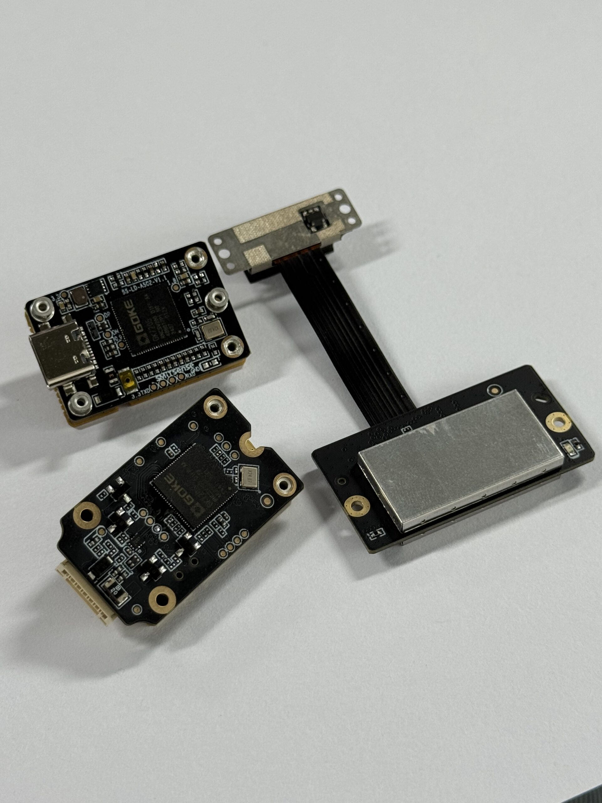
The DTOF Solid state LiDAR HM-LD1 is a compact SPAD dToF-based solid-state LiDAR module designed to output real-time depth images and 3D point cloud data for environmental perception. It is suitable for robotics obstacle avoidance, distance detection, autonomous navigation, UAV altitude sensing, terrain following, smart inspection, robotic vision development, object recognition, volume measurement, and zone intrusion monitoring. Its compact mechanical design, 28 g weight, 1.2 W power consumption, and support for UART, UDP, and UVC interfaces make it practical for embedded platforms, PCs, Raspberry Pi, flight controllers, and Linux-based robotics systems.
View Product Details & Pricing ➔

| Specification | DTOF Solid state LiDAR HM-LD1 |
|---|---|
| Product Name | DTOF Solid state LiDAR HM-LD1 |
| Technology | SPAD dToF solid-state LiDAR |
| Dimension | 43.5 mm × 30 mm × 26.5 mm |
| Weight | 28 g |
| Indoor Ranging Capability | 0.5–25 m |
| Outdoor Ranging Capability | 0.2–8 m |
| Ranging Accuracy | ±3 cm |
| Field of View | 60° horizontal × 45° vertical |
| Resolution | 40 × 30 |
| Frame Rate | 10 fps |
| Interfaces | UART / UDP / UVC |
| Operating Temperature | -20 ℃ to 60 ℃ |
| Power Consumption | 1.2 W |
| Supported Development Platforms | x86 Windows, x86 Linux, ARM Linux SDKs |
| Typical Applications | Obstacle avoidance, distance detection, autonomous navigation, UAV altitude hold, terrain following, smart inspection, robotic vision, object recognition, volume measurement, and zone intrusion monitoring |
Download the official brochure: DTOF SSL HM-LD1 Product Brochure
Why HM-LD1 Fits Compact Robotics
The HM-LD1 is designed for space-constrained systems where size, weight, and power matter. At 28 g and 1.2 W, it is suitable for compact AMRs, UAVs, embedded vision systems, inspection devices, and development platforms where a larger mechanical LiDAR or depth camera may be difficult to install.
That small size matters more than it may seem at first. Once a robot design includes covers, harnesses, battery placement, compute hardware, and mounting brackets, sensor volume becomes valuable. A compact solid-state module gives engineers more freedom to place the depth sensor where it actually sees the right area, instead of where it merely fits.
Outdoor and Indoor Ranging Use Cases
The module specifies 0.5–25 m indoor ranging capability and 0.2–8 m outdoor ranging capability. This distinction is important because bright outdoor environments can reduce optical signal-to-noise ratio. The product details also highlight accurate measurement at long distance outdoors, including use cases such as bridges, expressways, and dams where distance measurement may be needed in areas difficult for people to approach.
For indoor robotics, the 25 m specified range gives useful headroom for warehouses, corridors, large rooms, and industrial aisles. For outdoor or semi-outdoor machines, the 8 m specified outdoor range should be evaluated against stopping distance, speed, target reflectivity, and sunlight conditions. As always, test the actual target materials and mounting angles your robot will see in the field.
Platform Compatibility
With UART, UDP, and UVC support, HM-LD1 can be integrated into multiple system architectures. UART is useful for embedded control, UDP supports networked data streaming, and UVC can simplify camera-like access. SDK support for x86 Windows, x86 Linux, and ARM Linux helps developers work across PCs, Raspberry Pi, embedded Linux systems, and robotics platforms.
This flexibility is useful during both prototyping and production. A team might start with a PC or Raspberry Pi for development, move to Jetson for AI-assisted perception, and later integrate the same depth sensor into a custom embedded controller. Interface flexibility helps reduce the chance that the sensor choice forces a complete system redesign.
Engineering Deployment Checklist
- ⚙️ Define the required detection range for indoor, outdoor, daytime, and nighttime operation.
- ⚙️ Calculate robot stopping distance and match it with sensor frame rate and usable range.
- ⚙️ Check whether the field of view covers the robot’s full danger zone.
- ⚙️ Confirm whether the depth resolution is sufficient for the smallest obstacle size.
- ⚙️ Verify interface compatibility with the host system: UART, UDP, or UVC.
- ⚙️ Confirm SDK support for Windows, Linux, or ARM Linux.
- ⚙️ Test sensor performance under sunlight, reflective surfaces, dark targets, and angled targets.
- ⚙️ Validate mounting position, vibration resistance, cable routing, and enclosure protection.
- ⚙️ Integrate timestamping and coordinate transforms if used with ROS or SLAM.
- ⚙️ Run field tests in the actual robot environment before production deployment.
Common Mistakes to Avoid
Avoid choosing a DToF camera only by maximum range. Do not ignore outdoor sunlight performance, latency, mounting height, field of view, or calibration. Do not assume that point cloud output automatically equals complete SLAM. A depth sensor provides observations; the full robotic system still needs synchronization, transforms, mapping logic, and validation under real motion.
- ✅ Do not rely on a single perfect lab test. Run the sensor on the moving robot.
- ✅ Do not mount the sensor where the chassis, cables, or protective cover blocks part of the field of view.
- ✅ Do not ignore low obstacles, overhangs, and angled surfaces during testing.
- ✅ Do not assume indoor range numbers apply outdoors in full sun.
- ✅ Do not skip diagnostics. Operators need to know when the sensor is disconnected, dirty, saturated, or reporting invalid data.
Look, good robotics engineering is mostly about margins. You want enough range, enough update rate, enough field of view, enough compute, and enough validation to handle the real environment. A DToF camera can be a strong part of that system, but it should be selected and tested like any other critical sensing component.
Choose a Compact DToF Camera for Your Robotics Project
If your robot, UAV, or embedded vision system needs compact 3D depth sensing, the DTOF Solid state LiDAR HM-LD1 provides a practical combination of small size, low weight, low power consumption, real-time depth output, and flexible interfaces. With indoor ranging up to 25 m, outdoor ranging up to 8 m, ±3 cm accuracy, 60° × 45° FOV, UART/UDP/UVC support, and SDKs for x86 Windows, x86 Linux, and ARM Linux, it is suitable for prototyping and deployment across many robotics platforms.
For teams building AMRs, UAVs, inspection robots, smart monitoring devices, or embedded perception systems, the HM-LD1 is worth evaluating when the project needs more spatial detail than a single-point sensor but less size, weight, and mechanical complexity than a large scanning LiDAR. The best next step is to compare the sensor’s range, FOV, interface, and frame rate against your machine’s actual motion profile and test environment.
View Product Details & Pricing ➔
FAQ: DToF Camera for Robotics
What is the difference between a DToF camera and small ToF sensor packages?
Can a DToF camera work in low light or chaotic lighting environments?
Is a compact DToF camera easy to integrate with Raspberry Pi, Jetson, ROS, or embedded systems?
Can a DToF camera be used for SLAM?
Why is outdoor DToF range usually shorter than indoor range?
Is a 40 × 30 DToF resolution enough for robotics?
How important is frame rate for obstacle avoidance?
Can a DToF camera be used on drones?
📚 References & Further Reading
- Industry Standard: LiDAR technology overview
- Industry Reference: South Survey measurement and positioning technologies
- Related Guide: iToF vs DToF
- Related Guide: KF or BA for SLAM systems
- Related Guide: 3 core challenges in VIO systems
- Product: DTOF Solid state LiDAR HM-LD1