


LiDAR Images Explained: How to Find, View, and Use Depth Maps for Robotics, GIS, and 3D Perception
LiDAR images get called a lot of things: maps, point clouds, depth maps, range images, elevation models, and 3D scans. Here’s the deal: those terms are related, but they are not the same. A GIS analyst pulling airborne LiDAR from a government mapping portal may be working with LAS, LAZ, DEM, DSM, DTM, or GeoTIFF files. A robotics engineer, on the other hand, may be trying to read live depth frames from a compact LiDAR sensor for obstacle avoidance, SLAM, autonomous navigation, or industrial inspection. Same sensing family, very different job on the floor.
For industrial robotics, drones, smart cameras, automated inspection, and embedded vision, the most useful LiDAR image is often not a static public map. It is a real-time depth image generated by a sensor mounted directly on the machine. Those depth frames can be converted into point clouds, fused with cameras or IMUs, and used to detect obstacles, measure distance, build local maps, or support machine perception. This guide explains what LiDAR images are, where to find them, how to view them, and how compact solid-state sensors such as the DTOF Solid State LiDAR HM-LD1 output depth maps and 3D point cloud data for robotics development.
Table of Contents
- 👉 What Are LiDAR Images?
- 👉 Types of LiDAR Images and Data Formats
- 👉 How LiDAR Images Work
- 👉 Where to Find LiDAR Images and Maps
- 👉 How to View LiDAR Images on a PC
- 👉 LiDAR Depth Maps for Robotics and 3D Perception
- 👉 LiDAR Images for GIS, Mapping, and Terrain Analysis
- 👉 LiDAR Images vs Camera Images
- 👉 Real-Time LiDAR Images with DTOF Solid State LiDAR HM-LD1
- 👉 Integration Workflow for Engineers
- 👉 Common Mistakes When Using LiDAR Images
- 👉 Next Step: Choose the Right LiDAR Image Source
- 👉 FAQ About LiDAR Images
What Are LiDAR Images?
A LiDAR image is a visual or data-based representation of distance measurements captured with laser-based sensing. A normal camera records color, brightness, texture, and contrast. LiDAR records geometry and depth. In plain shop terms, it tells a system how far surfaces and objects are from the sensor. That distance information can be displayed as a colorized image, stored as a structured depth frame, projected into a 3D point cloud, or processed into terrain and elevation models for GIS workflows.
The phrase “LiDAR images” changes meaning depending on who is using it. In GIS and mapping, it may refer to hillshade maps, digital elevation models, point-cloud visualizations, or raster images derived from airborne LiDAR surveys. In robotics and automation, it usually means live depth images, range images, or point-cloud frames produced by a sensor mounted on a robot, UAV, inspection device, or smart machine. Both uses are legitimate. The important part is knowing which one you have, because the viewer, processing workflow, accuracy assumptions, and final application are completely different.
LiDAR Image vs LiDAR Point Cloud
A LiDAR point cloud contains measured points in 3D space. Each point usually includes X, Y, and Z coordinates, and it may also include intensity, timestamp, return number, classification, or color information. Point clouds are excellent for representing geometry, measuring distances, registering scans, building maps, and visualizing 3D environments. You see them in surveying, construction, archaeology, forestry, SLAM, robot navigation, and digital twin work.
A depth image is different. It is usually a structured 2D grid where each pixel or cell represents a distance measurement. For example, a 40 × 30 depth image contains 1,200 distance values per frame. That format is useful because many perception algorithms can process it like an image, even though the values represent depth instead of color. A depth image can be colorized for human viewing, thresholded to detect nearby obstacles, or projected into a point cloud when calibration and field-of-view parameters are known.
Why LiDAR Images Matter in Industrial Perception
In the shop, machines need reliable spatial information. A camera may show that an object exists, but it does not directly measure how far away that object is without extra processing. LiDAR depth maps help robots detect obstacles, estimate free space, measure clearance, support collision avoidance, and create local maps. In many industrial environments, surfaces are low texture, lighting changes all day, and visual appearance is not enough for safe navigation. LiDAR adds metric depth, which is exactly what a machine needs when it must make decisions based on distance instead of appearance.
For developers working with visual-inertial systems, LiDAR depth can complement VIO and VSLAM pipelines. Look, cameras are powerful, but they can struggle with poor visual features, motion blur, lighting changes, or scale drift. Depth measurements can improve perception robustness by giving the system real distance data. For related troubleshooting topics, see the VIO/VINS/VSLAM troubleshooting guide.
Types of LiDAR Images and Data Formats
LiDAR images can show up in many forms because LiDAR data gets transformed for different users. A surveyor, a GIS analyst, a robotics engineer, and a machine-vision developer may all say they use LiDAR, but they may not use the same data format or the same viewer. The key is to identify whether the data is a raster image, a point cloud, a depth frame, or a recorded sensor stream.
Depth Maps
A depth map is a 2D image-like grid where each pixel contains a distance value. Near objects may appear as warm colors and far objects as cool colors depending on the visualization palette, but the color is only a display method. The real value is the numeric distance behind each pixel. Depth maps are common in robotics, embedded vision, drones, inspection systems, smart cameras, and object detection workflows. Because they are structured, they can be processed efficiently for zone detection, obstacle segmentation, distance thresholding, and local environment perception.
✅ Depth maps are practical when an application needs fast near-field decisions. A mobile robot can check whether any pixel group inside a safety region is closer than a threshold. A UAV can use a downward-facing depth sensor to estimate ground distance. A smart inspection system can confirm whether a target object is present and within the expected range. You do not always need a huge point cloud to make a good control decision; sometimes a clean, reliable depth grid is the better engineering choice.
Point Clouds
Point clouds represent a measured scene as 3D coordinates. They may be sparse or dense depending on the sensor resolution, scanning method, and measurement frequency. Airborne mapping systems may produce very large point clouds covering cities, forests, roads, rivers, and infrastructure. Robotics systems may generate smaller but faster point-cloud frames for real-time perception. Point clouds are used for SLAM, 3D reconstruction, terrain modeling, volume estimation, industrial inspection, object detection, and digital twin creation.
✅ Point clouds are strong when spatial structure matters. If you need to register scans, build a 3D map, calculate volume, inspect deformation, or visualize the shape of a work area, point clouds are often the right representation. The tradeoff is that point-cloud processing can require more compute, more memory, and more careful calibration than simple depth-threshold logic.
Elevation Models: DEM, DSM, and DTM
In GIS, LiDAR data is frequently converted into elevation models. A DEM, or digital elevation model, generally represents terrain elevation. A DSM, or digital surface model, includes buildings, trees, and other objects on the surface. A DTM, or digital terrain model, usually refers to bare-earth terrain after vegetation and structures have been filtered out. These products are commonly used for flood modeling, slope analysis, construction planning, watershed studies, forestry, mining, and infrastructure design.
Look closely at the metadata before making engineering decisions from these products. Resolution, vertical accuracy, coordinate system, vertical datum, classification method, and collection date all matter. A hillshade can look clean and convincing, but if the underlying elevation data is old, misclassified, or referenced to the wrong datum, the final decision can still be wrong.
LAS, LAZ, GeoTIFF, PCD, PLY, and ROS Bag Files
Different LiDAR workflows use different data formats. GIS users commonly work with LAS, LAZ, and GeoTIFF. Robotics teams may work with PCD, PLY, ROS Bag files, live UDP streams, UVC depth streams, or vendor SDK outputs. Understanding the format helps you choose the correct viewer, processing tool, and conversion workflow.
| Format | Common Use | Typical Viewer |
|---|---|---|
| LAS | Standard LiDAR point cloud format | CloudCompare, ArcGIS, QGIS plugins |
| LAZ | Compressed LAS point cloud | CloudCompare, PDAL, Potree workflows |
| GeoTIFF | Raster elevation or hillshade imagery | QGIS, ArcGIS |
| PCD | Point Cloud Library workflows | PCL tools, robotics software |
| PLY | 3D mesh or point visualization | MeshLab, CloudCompare |
| ROS Bag | Recorded robotics sensor data | ROS, RViz |
Industrial LiDAR performance depends heavily on the emitter, receiver, optical stack, and time-of-flight sensing architecture. Component suppliers such as AMS Osram provide optical and sensing technologies used across advanced perception systems.
How LiDAR Images Work
LiDAR systems measure distance by emitting light and analyzing the reflected signal. The system sends a laser pulse or modulated light pattern toward a scene, receives the reflected light, and calculates how far the reflecting surface is from the sensor. The result may be one distance sample, a scan line, a 2D depth frame, or a 3D point cloud depending on the sensor architecture.
Time-of-Flight Distance Measurement
Time-of-flight measurement is one of the most important principles behind LiDAR images. The sensor emits light, waits for the return signal, and calculates distance based on the travel time of light. Direct time-of-flight, or dToF, measures photon return timing directly. SPAD-based receivers can detect very small amounts of returned light, making them useful in compact depth-sensing modules. That timing accuracy is what lets LiDAR generate reliable depth data instead of only visual appearance.
In practical engineering work, time-of-flight performance is affected by target reflectivity, ambient light, integration time, optics, signal processing, and the sensor’s internal filtering. A clean white target indoors is easy. A dark angled surface outdoors at noon is harder. That is why datasheet range numbers should be treated as starting points, not final proof that a sensor will perform perfectly in every installation.
From Distance Samples to Depth Images
Each pixel, channel, or scan direction in a LiDAR system can have an associated distance value. A structured LiDAR module can output a depth frame that resembles a low-resolution image, but every pixel contains range data. This image can be colorized to help engineers inspect the scene, but the real measurement remains numeric. Algorithms can use the depth values to identify near-field obstacles, detect empty space, estimate object size, or trigger safety actions.
✅ A depth image is useful because it preserves a simple relationship between measurement location and scene direction. Engineers can define regions of interest, compare distance bands, ignore known mechanical obstructions, or watch for sudden changes in a specific zone. That makes the format friendly for embedded controllers, PC tools, and robot middleware.
From Depth Images to 3D Point Clouds
Depth pixels can be projected into 3D space using calibration parameters. The horizontal and vertical field of view determine the angular coverage of the depth image, while the resolution determines how many measurement cells exist within that coverage. Once depth pixels are mapped into 3D coordinates, the output can be visualized as a point cloud or fused with camera and IMU data. This transformation is common in robotics, where structured depth frames are used for both efficient processing and spatial visualization.
Look, this is where calibration earns its paycheck. If the field of view, lens model, sensor pose, or timestamp alignment is wrong, the point cloud may look plausible but still be wrong enough to hurt mapping or obstacle detection. In a real robot, the LiDAR frame, camera frame, IMU frame, and base frame need to be handled consistently.
Important Performance Metrics
Important LiDAR image specifications include range, accuracy, resolution, frame rate, field of view, outdoor sunlight tolerance, power consumption, interface support, and SDK compatibility. Range determines how far the sensor can measure. Accuracy determines how close the reported distance is to the real distance. Resolution affects the detail of the depth image. Frame rate affects how quickly the system reacts to motion. Field of view determines coverage area. Interface support affects integration with PCs, embedded systems, flight controllers, and robot controllers.
For robotics and embedded development, these specifications are often more important than raw visual quality. A compact module with real-time depth output, known range limits, stable accuracy, and simple interfaces can be more practical than a large survey-grade scanner. Engineers should choose the LiDAR image source based on the task: mapping, detection, navigation, inspection, safety, or measurement.
Where to Find LiDAR Images and Maps
Users searching for LiDAR images often want downloadable maps, public datasets, or examples of LiDAR imagery. These are usually available through government mapping programs, research projects, municipal open-data portals, and geospatial data platforms. Public LiDAR images are valuable for analysis, simulation, planning, and mapping. They are not a replacement for onboard sensors when a robot needs live perception.
Public GIS and Government LiDAR Portals
National mapping programs often provide airborne LiDAR data. Users can search by country, state, province, county, city, watershed, transportation corridor, or survey region. Datasets may include point clouds, terrain models, flood maps, elevation rasters, and hillshade imagery. These resources are useful for environmental monitoring, infrastructure planning, hydrology, forestry, mining, and urban development.
✅ Before using public LiDAR data, check the coordinate reference system, vertical datum, resolution, collection date, license conditions, classification quality, and stated accuracy. In GIS work, those details are not paperwork clutter. They decide whether your layers line up, whether your elevation values are meaningful, and whether the dataset is appropriate for the decision you are making.
Research and Archaeology LiDAR Projects
Research and archaeology projects use LiDAR images to reveal terrain features, structures, and landscape patterns that may not be visible in ordinary photos. LiDAR can help detect old roads, foundations, terraces, earthworks, and vegetation-covered features. Academic datasets may also focus on forests, coastal erosion, snow depth, landslides, urban modeling, and infrastructure change. These datasets can be powerful for analysis, but commercial use may be restricted by licensing or citation requirements.
When Public LiDAR Images Are Not Enough
Public maps are usually static and may be months or years old. They cannot detect a new obstacle, a moving person, a vehicle, a pallet, or a changed construction zone. Robots, UAVs, and inspection devices need onboard LiDAR images generated in real time. Live depth frames allow machines to react to the current environment instead of relying only on historical map data. For readers comparing LiDAR-based perception with visual navigation, the guide on what LiDAR technology is provides a broader foundation.
How to View LiDAR Images on a PC
The best way to view LiDAR images on a PC depends on the source and file type. Public geospatial datasets usually require GIS or point-cloud software. Live LiDAR modules may require a vendor SDK, a UVC viewer, a UDP receiver, a serial tool, ROS, RViz, or custom application software. The first step is to identify whether you are working with offline files or a live sensor stream.
Viewing LAS and LAZ Point Clouds
LAS and LAZ files are common in mapping and surveying workflows. CloudCompare is useful for quick inspection, measurement, segmentation, and visualization. QGIS and ArcGIS are useful when LiDAR data must be combined with maps, orthophotos, property boundaries, or other geospatial layers. PDAL is useful for command-line processing, filtering, conversion, and automation. Potree is often used when large point clouds need to be published in a web browser for sharing or review.
✅ A good PC workflow starts with a simple inspection pass. Open the file, verify units, check coordinate placement, inspect density, confirm classification, and look for obvious gaps or noise. After that, move into filtering, clipping, raster generation, measurement, or conversion. Skipping inspection is how small metadata mistakes turn into expensive downstream problems.
Viewing GeoTIFF, DEM, and Hillshade Files
GeoTIFF and elevation raster files are commonly viewed in GIS software. They can be rendered as grayscale elevation images, hillshade maps, slope maps, contour layers, or color-relief terrain models. When viewing these files, coordinate reference systems must match other layers. Elevation values also require correct units and vertical datum verification. A visually attractive hillshade can be useful for interpretation, but engineering decisions should rely on the underlying elevation data and metadata.
Viewing Live Depth Maps from a LiDAR Module
For hardware modules, PC viewing depends on the sensor interface and SDK. UVC can simplify streaming because it behaves in a camera-like way for compatible systems. UDP is useful for network streaming and higher-level application integration. UART is common for embedded control, compact systems, and microcontroller or flight-controller integration. SDK support for Windows, Linux, and ARM Linux reduces development time because engineers can test visualization and data acquisition before building custom perception logic.
A module such as DTOF Solid State LiDAR HM-LD1 supports UVC, UDP, and UART interfaces, making it suitable for PC visualization as well as embedded robotics development. This flexibility is important when teams want to prototype on a desktop computer, validate depth images, and later deploy on a robot, UAV, or embedded Linux platform.
LiDAR Depth Maps for Robotics and 3D Perception
In robotics, LiDAR images are not just visual assets. They are machine perception inputs. A robot can use depth maps to understand nearby geometry, detect obstacles, estimate free space, create local maps, and make control decisions. Unlike static GIS datasets, live depth images update with the scene, allowing the robot to respond to people, moving equipment, changing terrain, or unexpected objects.
Obstacle Avoidance
Depth maps identify nearby objects in the robot’s path. Engineers can define safety zones, threshold distance values, and create stop or slow-down logic based on measured range. Frame rate and latency matter because moving platforms need timely data. A slow sensor may be acceptable for static inspection, but a mobile robot or UAV requires faster updates. Solid-state modules are useful where mechanical scanning parts are undesirable, space is limited, or reliability is important.
✅ In the shop, obstacle avoidance usually starts simple: define a near zone, define a warning zone, and define a clear zone. Then test the behavior with people, pallets, carts, posts, angled surfaces, and low-reflectivity targets. The smartest algorithm in the world still needs real-world validation around the things the robot will actually encounter.
SLAM and Local Mapping
LiDAR point clouds can help estimate robot motion and construct maps. Depth data can complement cameras in low-texture scenes, repetitive corridors, or difficult lighting. Fusion with VIO, wheel odometry, IMU, GNSS, or other sensors improves robustness. In some systems, stationary detection and motion constraints can also improve estimation. For related inertial navigation concepts, see ZUPT in VIO/VSLAM systems.
UAV Altitude Hold and Terrain Following
Downward-facing LiDAR provides direct distance to the ground, which is useful for UAV altitude hold, terrain following, landing assistance, and low-altitude inspection. Outdoor range and sunlight performance are critical because drones often operate in changing lighting conditions. Sensor weight also matters because every gram affects payload capacity, flight time, and mechanical design. A compact depth module can provide useful distance information without adding excessive weight.
Smart Inspection and Industrial Safety
LiDAR depth images support zone monitoring, user presence detection, object recognition support, volume measurement, and distance inspection. Industrial teams may use LiDAR to measure distances around bridges, expressways, dams, warehouses, factories, restricted zones, or machinery. Distance measurement can reduce human exposure to hazardous areas and improve automation reliability. In smart inspection systems, a LiDAR image may help confirm whether an object is present, how far away it is, and whether it has entered a safety region.
LiDAR Images for GIS, Mapping, and Terrain Analysis
GIS users often work with LiDAR images as terrain products, elevation models, hillshade visualizations, or classified point clouds. These datasets are powerful because LiDAR can capture elevation and surface geometry at large scale. Unlike live robotics LiDAR, GIS LiDAR is usually collected by aircraft, survey vehicles, tripods, drones, or mobile mapping platforms and then processed into deliverables for analysis.
Terrain Modeling
LiDAR reveals elevation changes in terrain with high precision. It is used for flood modeling, slope analysis, watershed mapping, erosion monitoring, construction planning, mining, forestry, and environmental management. Bare-earth models are especially valuable in vegetated areas because LiDAR processing can filter vegetation and estimate the underlying ground surface. Terrain models should always be checked for resolution, collection date, classification quality, and vertical accuracy.
Urban and Infrastructure Mapping
Point clouds can capture roads, buildings, bridges, powerlines, trees, signs, barriers, and other infrastructure. Municipal planning teams use LiDAR to support digital twins, asset inventories, road planning, vegetation management, and construction verification. Transportation agencies may use mobile LiDAR to analyze roads, tunnels, bridges, and rail corridors. In these workflows, LiDAR images are not only visual references; they are measurement datasets that support planning and engineering decisions.
Surveying and Measurement Workflows
Survey workflows require accuracy checks, control points, coordinate systems, and documented methods. LiDAR data may be combined with GNSS, total stations, photogrammetry, and mapping software to create complete measurement products. Surveying and geospatial workflows often combine LiDAR with GNSS, total stations, and professional mapping platforms. Providers such as South Survey represent the broader professional surveying ecosystem where point-cloud data is used for measurement and mapping.
LiDAR Images vs Camera Images
LiDAR images and camera images are both useful, but they measure different things. A camera records reflected visible light, producing rich color and texture. LiDAR measures distance, producing geometry and depth. Neither sensor is universally better. The best choice depends on the task, environment, required accuracy, cost, compute budget, and safety requirements.
What Cameras Do Better
Cameras capture color, texture, labels, signs, edges, and object appearance. They are excellent for classification, documentation, visual inspection, and AI recognition. Cameras usually offer higher pixel resolution and lower cost than LiDAR. They are also familiar to developers because image-processing and computer-vision ecosystems are mature. However, cameras may struggle when lighting changes, surfaces lack texture, scale is ambiguous, or direct distance is required.
What LiDAR Does Better
LiDAR provides direct distance measurement. It can measure geometry even when visual texture is weak or lighting is not ideal. This makes it valuable for obstacle distance, clearance analysis, 3D shape estimation, volume measurement, and safety monitoring. A LiDAR depth map can tell a robot that an object is one meter away, while a standard camera image alone does not directly provide that metric distance without additional estimation.
Why Sensor Fusion Is Often Best
Camera and LiDAR fusion combines semantics and geometry. The camera contributes color, appearance, and recognition features. LiDAR contributes scale, depth, and surface structure. An IMU adds motion information, while GNSS or wheel odometry can provide global or local positioning support. Robust robotics perception stacks often use multiple sensors to reduce failure modes. For example, a robot may use a camera for object recognition, LiDAR for distance, and an IMU for motion estimation.
Real-Time LiDAR Images with DTOF Solid State LiDAR HM-LD1
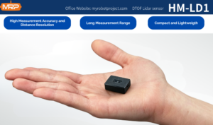
For engineers who need live LiDAR images rather than static downloadable maps, the DTOF Solid State LiDAR HM-LD1 provides real-time depth images and 3D point cloud data in a compact module. It is designed for obstacle avoidance, distance detection, autonomous navigation, smart inspection, UAV altitude hold, terrain following, user presence detection, object recognition support, volume measurement, zone intrusion monitoring, autofocus, and robotic vision development.
HM-LD1 is a solid-state LiDAR module based on SPAD dToF technology. It delivers real-time depth images and 3D point cloud data for accurate environmental perception. It supports indoor or nighttime ranging up to 25 meters and outdoor daytime ranging up to 8 meters. With UVC, UDP, and UART interfaces, it can be integrated with PCs, Raspberry Pi systems, flight controllers, and embedded platforms for both prototyping and system deployment.
View Product Details & Pricing ➔
Learn more about the DTOF Solid State LiDAR HM-LD1 or download the DTOF SSL HM-LD1 Product Brochure for detailed integration planning.
| Specification | DTOF Solid State LiDAR HM-LD1 |
|---|---|
| Dimension | 43.5mm × 30mm × 26.5mm |
| Ranging Capability | Indoor: 0.5–25m; Outdoor: 0.2–8m |
| Ranging Accuracy | ±3cm |
| Field of View | 60° horizontal × 45° vertical |
| Weight | 28g |
| Resolution | 40 × 30 |
| Frame Rate | 10fps |
| Interface | UART / UDP / UVC |
| Operating Temperature | -20℃ to 60℃ |
| Power Consumption | 1.2W |
| Development Platform Support | SDKs for x86 Windows, x86 Linux, and ARM Linux |
Why HM-LD1 Is Relevant to LiDAR Images
HM-LD1 is relevant because it outputs depth images and point cloud data rather than only single-point distance readings. A 40 × 30 resolution depth frame provides 1,200 distance points per frame, creating a compact real-time distance grid. At 10fps, the module can update scene measurements for many embedded perception use cases. This makes it useful for practical robot perception tasks where the system needs to know whether an object is near, how far away a surface is, and whether a safety zone is occupied.
Industrial and Robotics Use Cases
The module supports multiple applications for drones, robots, cameras, and security systems. It can enable UAV altitude hold and terrain following, assist robot navigation, support obstacle avoidance, contribute to SLAM workflows, and provide distance data for smart inspection. It can also support autofocus, user presence detection, object recognition, volume measurement, and zone intrusion monitoring. For infrastructure applications, outdoor distance measurement can help inspect objects that are difficult or unsafe for people to approach, such as bridges, expressways, and dams.
Integration Advantages
UVC simplifies PC visualization by allowing camera-style streaming in compatible workflows. UDP supports networked data transfer, which is useful for development systems and distributed architectures. UART supports embedded controllers and flight controllers where compact communication is needed. The 28g weight is valuable for drones and mobile robots, while the compact housing supports space-constrained devices. Low 1.2W power consumption also supports battery-powered systems where thermal and energy budgets are important.
Integration Workflow for Engineers
Choosing a LiDAR image source is not only a purchasing decision. It is an integration decision. Engineers should define the required data type, match specifications to operating conditions, choose the correct interface, and validate performance in the real environment. The goal is not just to see a LiDAR image on a screen. The goal is to convert depth data into reliable application logic.
Step 1: Define the Required LiDAR Image Type
⚙️ Start by deciding whether the application needs a depth image, a point cloud, or both. A depth image may be enough for near-object detection, safety zones, and embedded logic. A point cloud may be necessary for 3D visualization, SLAM, mapping, or spatial measurement. Also define whether the requirement is visualization only or algorithm input. A developer demo may only need a viewer, while a robot control system needs stable numeric depth data.
Step 2: Match Range, Accuracy, and Field of View
⚙️ Range differs between indoor, nighttime, and outdoor daytime conditions. Outdoor sunlight can reduce usable range, so engineers should evaluate real operating environments rather than relying on ideal conditions. Accuracy affects safety thresholds and measurement reliability. Field of view determines how much of the scene is covered. A wider field of view can cover more area, while the resolution determines how detailed the depth grid is within that coverage.
Step 3: Choose the Interface
⚙️ Interface selection affects development speed and deployment architecture. UVC is useful for quick PC viewing and camera-style workflows. UDP is useful for network streaming and application integration. UART is useful for embedded controllers, flight controllers, and compact systems. SDK availability is also important. Support for x86 Windows, x86 Linux, and ARM Linux can reduce development friction when moving from desktop testing to embedded deployment.
Step 4: Convert Depth Frames into Application Logic
⚙️ After receiving depth frames, engineers can segment near objects, filter noise, generate safety zones, convert depth pixels to 3D points, and feed data into SLAM, mapping, or control algorithms. The raw visual display is only the beginning. The real value comes from reliable interpretation of numeric distance values. For example, a robot may define a near-field stop zone, a slow-down zone, and a free-space zone based on measured depth.
Step 5: Validate in Real Environments
⚙️ Validation should include sunlight, reflectivity, temperature, vibration, motion, target color, and distance tests. Engineers should test edge cases such as glass, black surfaces, water, high-reflectivity objects, angled surfaces, and fast motion. Measurements should be compared against known distances. If the system will operate outdoors, validation should include the expected sunlight conditions. If the system will operate on a UAV or mobile robot, vibration and motion should also be considered.
Common Mistakes When Using LiDAR Images
LiDAR images are powerful, but they can be misunderstood. Many errors come from treating a visualization as raw data, ignoring coordinate systems, overvaluing resolution, or using static maps for real-time robotics. Avoiding these mistakes improves both analysis quality and engineering reliability.
Confusing Visualization with Measurement Data
A colorized depth image is not the raw measurement. The colors are chosen for human viewing and may exaggerate or hide distance differences depending on the palette. Engineers should always check numeric distance values, units, scaling, invalid pixels, and filtering rules. In GIS, a hillshade is a visualization, while the underlying elevation raster contains the measurement values. In robotics, a depth display is helpful, but the control system should use calibrated numeric depth data.
Ignoring Coordinate Systems
GIS data requires correct coordinate reference systems, units, and vertical datums. If coordinate systems are mismatched, layers may appear shifted or measurements may be wrong. Robotics data also requires coordinate discipline. The sensor frame, robot frame, camera frame, IMU frame, and world frame must be calibrated and transformed correctly. A depth image may look reasonable, but incorrect extrinsic calibration can cause mapping and obstacle detection errors.
Assuming Higher Resolution Is Always Better
Resolution matters, but it is not the only specification. Frame rate, latency, accuracy, field of view, range, sunlight performance, power consumption, size, cost, and integration simplicity also matter. A compact depth grid may be better than a high-density scanner for a small robot, drone, or embedded safety system. The best LiDAR image source is the one that meets the system requirement, not necessarily the one with the largest point cloud.
Using Static Maps for Real-Time Robotics
Public LiDAR maps cannot detect moving obstacles or recent changes. They may support route planning, simulation, environmental analysis, or prior mapping, but they do not replace onboard perception. A robot operating in a warehouse, construction site, factory, or outdoor inspection environment needs live depth data to respond to the current scene. Static maps and live LiDAR sensors can complement each other, but they serve different roles.
Next Step: Choose the Right LiDAR Image Source
If your goal is GIS analysis, start with public LiDAR datasets and view them in tools such as CloudCompare, QGIS, ArcGIS, PDAL, or Potree. Check the file format, coordinate system, collection date, vertical datum, and license before using the data for engineering decisions. Public LiDAR images are excellent for terrain modeling, infrastructure planning, archaeology, forestry, flood analysis, and large-scale spatial understanding.
If your goal is robotics, drones, smart inspection, or embedded 3D perception, choose a LiDAR module that can output live depth maps and point clouds with suitable range, accuracy, field of view, interface support, and SDK compatibility. For compact real-time sensing, explore the DTOF Solid State LiDAR HM-LD1 and download the product brochure for detailed integration planning.
FAQ About LiDAR Images
Where can I get LiDAR images or LiDAR maps?
How do I download and view LiDAR images on a PC?
Are LiDAR images better than photos for 3D modeling and perception?
What is the difference between a LiDAR depth map and a point cloud?
Can LiDAR images be used for robot obstacle avoidance?
What software can open LiDAR image files?
What specifications matter most when choosing a LiDAR sensor for images?
Can I use public LiDAR maps for autonomous robots?
Are LiDAR images affected by sunlight or weather?
How are LiDAR images used with SLAM?
📚 References & Further Reading
- Industry Standard: AMS Osram
- Industry Standard: South Survey
- Related Guide: VIO/VINS/VSLAM troubleshooting guide
- Related Guide: ZUPT in VIO/VSLAM systems
- Related Guide: What LiDAR technology is
- Product Resource: DTOF Solid State LiDAR HM-LD1
- Product Brochure: DTOF SSL HM-LD1 Product Brochure






