Drone with Collision Avoidance: How to Build Safer UAV Obstacle Detection with dToF LiDAR
A drone with collision avoidance is no longer just a premium consumer feature. Out in the field, it is becoming a basic engineering requirement. Industrial UAV inspection, autonomous navigation, indoor flight, terrain following, security patrols, warehouse robotics, and low-altitude inspection all need some level of obstacle awareness. But here’s the deal: real-world collision avoidance is a lot harder than spotting a tree on a sunny afternoon. Thin wires, dark surfaces, glass, changing sunlight, GPS-denied spaces, reflective metal, propeller vibration, and fast closing speeds can all cause a drone to misjudge distance or miss an obstacle entirely. For engineers and UAV builders, the real question is not simply “Does the drone have obstacle avoidance?” It is “What sensing architecture makes collision avoidance reliable enough for the mission?”
This guide explains how to build safer UAV obstacle detection using dToF LiDAR, a depth-sensing technology that measures real distance using direct time-of-flight light pulses. We will break down collision avoidance architecture, compare common drone obstacle avoidance sensor options, show where LiDAR fits into UAV systems, and introduce the compact DTOF Solid state LiDAR HM-LD1 as a lightweight module for UAV obstacle detection, altitude hold, terrain following, and autonomous navigation. With a 28g body, 60° × 45° field of view, real-time depth output, UART/UDP/UVC interfaces, and outdoor ranging up to 8m, HM-LD1 is designed for developers who need practical 3D perception without adding bulky payload weight.
Table of Contents
- 👉 What Is a Drone with Collision Avoidance?
- 👉 Why Drones Still Crash Near Obstacles
- 👉 How UAV Collision Avoidance Works
- 👉 Sensor Technologies Used in Drone Obstacle Detection
- 👉 Why dToF LiDAR Is Useful for UAV Obstacle Detection
- 👉 Recommended Architecture for a Drone with Collision Avoidance
- 👉 How to Integrate dToF LiDAR into a UAV Platform
- 👉 DTOF Solid State LiDAR HM-LD1 for Drone Obstacle Detection
- 👉 Industrial Application Scenarios for dToF-Based Drone Collision Avoidance
- 👉 Engineering Checklist Before Choosing a Drone Collision Avoidance Sensor
- 👉 FAQ: Drone with Collision Avoidance
What Is a Drone with Collision Avoidance?
A drone with collision avoidance is a UAV equipped with sensors, onboard processing, and control logic that allow it to detect nearby obstacles and respond before impact. The response may be a pilot warning, speed reduction, emergency braking, altitude correction, rerouting, hover hold, or a controlled fail-safe action. In industrial settings, collision avoidance is not only about protecting the aircraft. It also protects people, infrastructure, payloads, production assets, and the operational continuity of inspection or mapping missions.
Look, it helps to separate a few terms that often get mixed together. Obstacle detection means sensing that something is nearby. Obstacle avoidance means generating a motion response to avoid impact. Navigation means planning a path through an environment. Autonomy means executing decisions without constant pilot input. Fail-safe behavior means responding safely when sensor data becomes unreliable, delayed, saturated, or physically blocked.
Collision Avoidance Is a System, Not a Single Feature
A drone cannot avoid obstacles simply because one sensor is installed on the airframe. It needs distance measurement, field-of-view coverage, environmental interpretation, low-latency processing, flight controller integration, safety logic, and a defined response when data quality degrades. The sensor is only the first layer. The full drone anti-collision system must include software that converts raw measurements into actionable flight behavior.
For example, a forward-facing depth sensor may detect a wall at 4m. That information is not useful unless the onboard processor knows the UAV speed, stopping distance, direction of travel, sensor confidence, and whether the flight controller can accept a command to slow, stop, climb, or replan. In the shop, this is where a lot of prototypes fail: the sensor works on the bench, but the aircraft does not know what to do with the data. A reliable UAV collision avoidance architecture must be designed around the airframe, flight envelope, environment, payload, and mission risk.
Consumer vs Industrial Collision Avoidance
Consumer drones often use front, rear, bottom, or omnidirectional vision systems to protect pilots during photography and recreational flight. These systems can be very useful, but they are usually optimized for common visual obstacles, pilot-assist behavior, and controlled consumer use cases. Industrial UAVs may operate in more complex conditions: under bridges, near dams, inside warehouses, around steel beams, close to power infrastructure, between trees, near cranes, and in GPS-denied environments.
Industrial UAV integrators often require a more modular architecture. They may need to add a dedicated depth sensor for drone applications, combine it with cameras, fuse it with IMU or positioning data, or process depth frames on a companion computer. For more perception and LiDAR-related updates, see the latest LiDAR news.
Why Drones Still Crash Near Obstacles
Even drones marketed as having collision avoidance may still crash because real environments do not behave like test charts. Sensing is limited by direction, range, lighting, object material, data rate, processor latency, aircraft speed, and control authority. A system may work well in a bright outdoor park but struggle inside a warehouse with reflective floors, poor lighting, repetitive shelf patterns, or narrow aisles.
Blind Spots and Limited Directional Coverage
Many drone collision avoidance systems protect only selected directions. A drone may have front-facing sensors but no side, rear, upward, or full downward coverage. If the UAV turns sideways, ascends into a branch, backs into a wall, or flies under an overhang, uncovered directions become crash risks. This is why engineers should treat field-of-view planning as a system-level design task. A 60° horizontal field of view is valuable for forward detection, but it does not create full 360° protection by itself.
Cameras Can Struggle in Low Light or High Glare
Vision systems need texture, sufficient illumination, stable exposure, and suitable scene geometry. They may fail in low-light indoor spaces, direct sunlight, fog, repetitive patterns, reflective floors, or featureless walls. Stereo vision in particular needs visible features in both camera images to estimate depth through disparity. If the scene lacks texture or the camera is overexposed, depth estimation can become unreliable.
Thin and Reflective Obstacles Are Difficult
Wires, cables, branches, glass, and metallic surfaces are among the most challenging objects for drone obstacle detection. Thin obstacles may occupy only a few pixels or a small portion of a sensor’s field of view. Glass may reflect, transmit, or distort signals depending on angle and wavelength. Dark surfaces may reduce return strength. Highly reflective surfaces may produce inconsistent readings. No honest engineer should call any UAV “crash-proof.” The right phrase is “risk-reduced within a defined operating envelope.”
Return-to-Home Is Not Always Obstacle-Aware
Many crashes occur during return-to-home because the drone follows a simplified route back to the home point. It may climb to a configured altitude, fly a straight path, descend near trees, or rely on sensors with limited directional coverage. If the RTH logic does not incorporate real-time 3D obstacle detection, the drone may still collide with cables, cranes, branches, building edges, or indoor structures.
Speed and Latency Matter
A sensor may detect an obstacle, but if the drone is flying too fast or the software pipeline is too slow, there may not be enough stopping distance. Collision avoidance is a timing problem. The total reaction window includes sensor exposure, frame rate, data transmission, parsing, filtering, risk calculation, command generation, flight-controller response, motor response, and physical deceleration. Industrial LiDAR adoption is also visible across the broader perception market, including suppliers such as Hesai Technology.
How UAV Collision Avoidance Works
UAV collision avoidance is best understood as a pipeline from sensing to action. Each stage must operate reliably and quickly. If any stage is poorly designed, the entire system can fail even if the sensor itself is high quality.
Step 1 — Sensing the Environment
Sensors collect distance, image, motion, radar, or depth data. For a drone with collision avoidance, the sensor must provide information quickly enough to support flight decisions. A dToF LiDAR module can generate a depth map. A stereo camera can estimate disparity. An optical flow camera can support motion estimation. Ultrasonic sensors can provide short-range distance. Radar can provide range and velocity information. A 3D point cloud can support mapping and spatial segmentation.
Step 2 — Obstacle Detection
The system filters raw data and identifies possible obstacles. A depth image can be divided into distance regions such as safe zone, warning zone, braking zone, and emergency stop zone. In a simple implementation, the processor may find the minimum valid distance in each field-of-view segment. In a more advanced implementation, it may cluster points, track obstacle motion, classify regions, or build an occupancy map.
Step 3 — Risk Assessment
The UAV estimates collision risk based on distance to obstacle, relative speed, direction of travel, aircraft braking capability, sensor confidence, mission priority, and available escape path. A stationary obstacle directly ahead is more urgent than a side obstacle outside the flight path. A close obstacle during fast forward flight requires stronger braking than the same obstacle during a slow hover maneuver.
Step 4 — Avoidance Decision
The system decides whether to stop, slow down, climb, descend, move sideways, replan the path, hold position, or warn the pilot. Industrial systems often prefer predictable behavior over aggressive avoidance. For example, a bridge inspection UAV may be programmed to slow and hold distance rather than make a sudden lateral maneuver near structural elements.
Step 5 — Flight Controller Execution
The avoidance command must be translated into flight-control behavior. Depending on the platform, this could involve velocity setpoints, position setpoints, attitude constraints, altitude hold input, terrain following correction, or emergency braking. This stage is critical because a perception system that cannot safely command the aircraft is only an alerting tool, not a true avoidance system.
Step 6 — Fail-Safe Behavior
Good fail-safe design defines what happens if the sensor loses data, becomes saturated, reports inconsistent measurements, or is physically blocked. Safe responses may include slowing down, hovering, switching flight modes, increasing manual pilot authority, disabling autonomous forward motion, or landing in a controlled manner. Fail-safe behavior should be tested, not assumed.
Sensor Technologies Used in Drone Obstacle Detection
There is no universal best drone obstacle avoidance sensor. Each technology has strengths, weaknesses, and mission-specific tradeoffs. A robust industrial UAV may combine several sensor types to compensate for individual limitations.
Stereo Vision
Stereo cameras estimate depth using disparity between two images. They provide rich visual information and can be cost-effective for forward obstacle detection and visual navigation. Their limitations include dependence on texture, lighting, calibration, baseline geometry, and processing power. In low-texture environments or glare-heavy scenes, stereo depth may degrade.
Monocular Vision and AI Detection
Single cameras can identify objects using machine learning, but they do not naturally measure precise distance unless combined with motion estimation, AI depth prediction, or other sensors. Monocular AI can be excellent for recognizing people, vehicles, doors, signs, or known hazards, but a collision avoidance controller still needs reliable range information.
Ultrasonic Sensors
Ultrasonic modules are low-cost and useful for short-range altitude sensing or simple proximity detection. However, they typically have limited range, low angular resolution, slower update behavior, and performance issues with soft, angled, narrow, or absorbent surfaces. They are commonly used for landing assist or basic height measurement rather than full UAV collision avoidance.
Millimeter-Wave Radar
Radar performs well in dust, fog, and some harsh environments. It can detect range and velocity, making it valuable for moving objects and poor-visibility conditions. Its limitation is spatial detail. Small or complex obstacles may be harder to resolve compared with LiDAR or camera-based systems, depending on radar design and signal processing.
Scanning LiDAR
Mechanical or rotating LiDAR can provide rich spatial mapping capability and is widely used in robotics, autonomous vehicles, and mapping systems. For smaller drones, however, size, payload weight, moving parts, power draw, and cost may be concerns. Scanning LiDAR can be excellent for mapping and SLAM when the UAV can carry the payload and process the data.
Solid-State dToF LiDAR
Solid-state dToF LiDAR is compact and has no large rotating mechanism. It can output real-time depth maps and point cloud data, making it useful for UAV obstacle detection, low-altitude navigation, terrain following, robotic vision development, and embedded perception. For compact drones, the combination of direct distance measurement, low weight, and depth-frame output can be highly practical.
| Sensor Type | Strengths | Limitations | Typical UAV Use |
|---|---|---|---|
| Stereo Vision | Rich visual data, good for textured scenes | Lighting-sensitive, processing-heavy | Forward obstacle detection, visual navigation |
| Ultrasonic | Low cost, simple distance sensing | Short range, low resolution, surface-dependent | Landing assist, basic altitude sensing |
| Radar | Works in dust, fog, and poor visibility | Lower spatial detail for small objects | Harsh environment detection, velocity sensing |
| Scanning LiDAR | High spatial mapping capability | Can be larger, heavier, and more expensive | Mapping, SLAM, industrial autonomy |
| Solid-State dToF LiDAR | Compact, depth maps, real distance data | Range and FOV must match mission design | Obstacle avoidance, terrain following, robotic vision |
Why dToF LiDAR Is Useful for UAV Obstacle Detection
dToF LiDAR for drones is attractive because it gives the control system real distance data. A camera may show that an object exists, but an avoidance controller needs to know how far away it is and how quickly the aircraft is approaching. Direct depth information allows simpler safety-zone logic and more deterministic behavior.
What Direct Time-of-Flight Means
Direct time-of-flight measures the time it takes for emitted light to travel to an object and return to the sensor. Because the speed of light is known, the sensor calculates distance from the measured time delay. In practice, the quality of the measurement depends on optical design, target reflectivity, ambient light, signal processing, and calibration.
Why Real Distance Data Matters
A drone with collision avoidance needs range, not just imagery. Real distance data allows the system to define braking thresholds, trigger slowdowns, maintain clearance from infrastructure, estimate ground height, and support terrain following. For controlled UAV obstacle detection, a depth map can be processed into zones quickly and efficiently.
Depth Map vs Point Cloud
A depth map represents distance values across a 2D sensor grid. Each pixel or measurement cell corresponds to a distance estimate in the field of view. A point cloud converts depth values into 3D spatial coordinates. For UAV obstacle avoidance, a depth map is often efficient for fast zone detection, while a point cloud can support mapping, SLAM, object segmentation, and navigation.
Benefits of Solid-State Design
Solid-state LiDAR modules can be easier to integrate into compact drones because they avoid bulky mechanical rotation. Benefits include smaller size, lower weight, easier mounting, potentially improved durability, lower power draw, and more direct integration with embedded systems. For UAV platforms where every gram affects flight time, compact solid-state design is an important advantage.
Where dToF LiDAR Works Best on Drones
dToF LiDAR can be installed in several orientations. A front-facing module supports forward obstacle detection. A downward-facing module supports altitude hold, landing assist, and terrain following. A rear-facing module improves reverse flight safety. Side-facing modules can support wall following or corridor navigation. A multi-module array can broaden coverage, although integration complexity increases with each additional sensor.
Recommended Architecture for a Drone with Collision Avoidance
A reliable drone with collision avoidance needs a clear architecture that connects sensing, computation, control, and safety. The architecture should be designed before selecting components, because the best sensor choice depends on data rate, interface, field of view, range, mounting location, software stack, and flight-control method.
Basic Architecture
A practical UAV collision avoidance system may include the UAV frame and propulsion system, a flight controller, a dToF LiDAR module, a companion computer or embedded processor, regulated power, a communication interface, avoidance software, and a flight-control integration layer. The companion computer may process depth frames and send velocity or position commands to the flight controller.
Data Flow
The data flow typically begins when the LiDAR captures a depth frame. The sensor sends data over UART, UDP, or UVC. The companion computer parses the depth data, filters noise and invalid pixels, calculates obstacle zones, estimates risk, and generates an avoidance command. The flight controller then receives a velocity, position, altitude, or braking command, causing the UAV to slow, stop, climb, descend, or reroute depending on the mission logic.
Example Collision Zones
For an outdoor module range up to 8m, an integrator may configure zones such as 6–8m for early detection, 3–6m for caution, 1.5–3m for braking, and under 1.5m for emergency response. These values are only examples. Actual thresholds depend on drone speed, braking performance, payload, wind, control latency, propeller response, and acceptable mission risk.
Sensor Fusion
dToF LiDAR can be combined with an IMU for motion compensation, a barometer for altitude context, GNSS or RTK for outdoor positioning, optical flow for indoor stabilization, a camera for classification, and radar for harsh weather support. For developers comparing positioning and query-based data workflows, this related article on RTK Query explained may be useful from a software architecture perspective, especially when thinking about how structured data moves through a system.
Need a compact depth sensor for UAV obstacle detection? Explore the DTOF Solid state LiDAR HM-LD1 for lightweight dToF LiDAR integration.
How to Integrate dToF LiDAR into a UAV Platform
Integrating a drone altitude hold sensor or LiDAR obstacle avoidance module requires more than wiring the sensor. The engineer must define the requirement, select the mounting direction, manage vibration, choose the interface, process depth frames, validate the behavior, and test failure modes. In other words, do not bolt it on Friday afternoon and expect Monday-morning autonomy.
Step 1 — Define the Collision Avoidance Requirement
Before selecting a sensor, define whether the aircraft operates indoors, outdoors, or both. Determine maximum UAV speed, minimum stopping distance, obstacle size, directional coverage, required field of view, weight limit, power budget, processing platform, and environmental conditions. A warehouse inspection drone has different requirements than a fast outdoor mapping UAV.
Step 2 — Choose Mounting Direction
A single front-facing module improves forward safety. A downward-facing module helps with altitude hold, landing, and terrain following. Side-facing modules can support corridor navigation, wall following, or close inspection. Industrial drones may require multiple modules, but each additional module increases wiring, processing, calibration, and power complexity.
Step 3 — Manage Vibration and Alignment
Drones produce vibration that can affect sensor readings and mechanical stability. Use a rigid but isolated mounting strategy, define the sensor angle relative to the drone body frame, calibrate the position and orientation, and protect the field of view from propeller wash, landing gear, payloads, cables, and protective covers. Alignment errors can cause incorrect obstacle zones and unsafe responses.
Step 4 — Connect the Interface
HM-LD1 supports UART, UDP, and UVC, allowing integration with embedded systems, PCs, Raspberry Pi, and development platforms. UART is useful for simple embedded connections. UDP is suitable for network-based data transfer to a companion computer. UVC can be convenient when the module is used like a camera or depth stream during development.
Step 5 — Process Depth Data
A typical processing pipeline reads each depth frame, removes invalid points, applies temporal smoothing, divides the field of view into zones, finds the minimum reliable distance in each zone, estimates collision risk, and outputs a command or warning. More advanced systems may use point-cloud clustering, motion compensation, semantic camera data, or local path planning.
Step 6 — Test in Controlled Conditions
Testing should begin with static indoor wall detection, then slow manual approach, hover and yaw tests, low-speed autonomous stop, outdoor sunlight validation, mission-specific obstacle trials, and fail-safe testing. Avoid enabling aggressive autonomous avoidance until the system has demonstrated stable behavior at low speed and in predictable environments.
DTOF Solid State LiDAR HM-LD1 for Drone Obstacle Detection
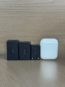
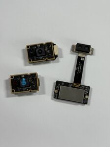
The DTOF Solid state LiDAR HM-LD1 is a compact SPAD dToF LiDAR module designed for real-time depth sensing and 3D perception. For a drone with collision avoidance, the key advantages are low weight, compact size, outdoor ranging capability, real depth output, and flexible interfaces for embedded integration. It supports obstacle avoidance, distance detection, autonomous navigation, smart inspection, and robotic vision development.
Learn more about the module here: DTOF Solid state LiDAR HM-LD1.
View Product Details & Pricing ➔
| Specification | DTOF Solid state LiDAR HM-LD1 |
|---|---|
| Product Name | DTOF Solid state LiDAR HM-LD1 |
| Technology | SPAD dToF solid-state LiDAR |
| Dimensions | 43.5mm × 30mm × 26.5mm |
| Weight | 28g |
| Ranging Capability | Indoor: 0.5–25m; Outdoor: 0.2–8m |
| Ranging Accuracy | ±3cm |
| Field of View | 60° horizontal × 45° vertical |
| Resolution | 40 × 30 |
| Frame Rate | 10fps |
| Interfaces | UART / UDP / UVC |
| Operating Temperature | -20℃ to 60℃ |
| Power Consumption | 1.2W |
| Development Support | SDKs for x86 Windows, x86 Linux, and arm Linux |
| Typical UAV Uses | Obstacle avoidance, altitude hold, terrain following, autonomous navigation, robotic vision development |
Why These Specs Matter for UAV Integration
Weight: 28g. A 28g module is suitable for small and medium UAV platforms where payload weight directly affects flight time, maneuverability, battery sizing, and available payload margin. Lightweight sensing is especially important when adding perception to drones that were not originally designed for heavy mapping payloads.
Outdoor range: 0.2–8m. Outdoor obstacle detection up to 8m gives a UAV time to detect nearby obstacles during slow and medium-speed flight. Integrators must still match detection range to speed and braking distance. An 8m detection envelope may be practical for controlled inspection and low-altitude navigation, but fast autonomous flight requires additional planning and a larger safety margin.
Indoor range: 0.5–25m. Indoor or nighttime ranging capability up to 25m can be valuable for warehouses, tunnels, indoor inspection, robotics laboratories, and GPS-denied environments. Indoor range is particularly useful when the scene has limited texture and camera-based depth estimation becomes less reliable.
FOV: 60° × 45°. A 60° horizontal and 45° vertical field of view is useful for front-facing obstacle zones or downward terrain sensing. It does not create omnidirectional protection by itself, so engineers should design mounting direction and sensor quantity around the expected collision directions.
Resolution: 40 × 30. The 40 × 30 depth resolution provides structured distance information for zone-based avoidance, object proximity detection, and depth-map processing. It is not intended to replace high-density mapping LiDAR, but it can provide practical depth awareness for compact UAV and robotics applications.
Frame rate: 10fps. A 10fps depth stream can support controlled obstacle detection and proximity awareness when UAV speed and control latency are designed accordingly. As with any perception system, the aircraft speed should be limited so that the UAV can react within the available sensor update window.
Interfaces: UART / UDP / UVC. Multiple interfaces make the module suitable for embedded controllers, companion computers, PCs, Raspberry Pi, and Linux development environments. This flexibility helps teams prototype on a PC, develop on a Raspberry Pi or Linux computer, and later integrate into an embedded UAV platform.
Operating temperature: -20℃ to 60℃. This operating range supports many robotics and UAV development scenarios, including indoor industrial sites and outdoor inspection environments. Final mission validation should still account for enclosure heating, direct sunlight, airflow, and local thermal conditions.
Power consumption: 1.2W. Low power draw is important on drones because the sensing payload competes with propulsion, communication, computing, and mission equipment. A 1.2W module is easier to budget into small UAV electrical systems than high-power perception payloads.
Point cloud and depth map output. HM-LD1 can provide ranging measurement data displayed as point cloud and depth data. For UAV engineers, this means the module can be used for simple safety-zone detection or more advanced perception workflows depending on the processing platform and software stack.
Development support. MRP offers SDKs for x86 Windows, x86 Linux, and arm Linux, enabling development and integration across diverse operating systems and architectures. This is useful for robotics engineers who need to move from bench testing to embedded deployment.
For UAV developers, robotics engineers, and embedded vision teams, HM-LD1 provides a compact path to real-time depth perception. View product details or download the DTOF SSL HM-LD1 Product Brochure.
Industrial Application Scenarios for dToF-Based Drone Collision Avoidance
dToF-based drone collision avoidance can support a range of industrial UAV applications. The value is strongest where the drone must fly close to structures, operate in constrained spaces, maintain distance, or estimate height above nearby surfaces.
Bridge, Dam, and Infrastructure Inspection
Industrial inspection drones often fly near concrete, steel, cables, beams, towers, and uneven surfaces. dToF LiDAR can help maintain distance from structures and support safer approach behavior. For bridge or dam inspection, a forward-facing or angled depth sensor can help the UAV detect approaching surfaces while the pilot or autonomy system focuses on the inspection path.
Warehouse and Indoor Navigation
Indoor UAVs cannot rely on GNSS. Depth sensing helps detect walls, shelves, forklifts, inventory racks, people, hanging signs, and loading equipment. A compact solid-state LiDAR module can support indoor proximity detection, altitude hold, and controlled movement through aisles when paired with appropriate flight-control logic.
Low-Altitude Terrain Following
A downward-facing dToF LiDAR module can help estimate ground distance and support altitude control over uneven surfaces. This is valuable for agriculture, inspection, security, and robotics missions where maintaining a consistent height above ground or infrastructure is more important than maintaining barometric altitude.
Smart Security and Zone Monitoring
Drones used for patrol or surveillance may use depth sensing to avoid walls, fences, vehicles, poles, and unexpected obstacles. In a smart security context, depth sensing can also support zone intrusion monitoring or object presence detection when the aircraft is hovering or moving slowly through a defined patrol area.
Robotics and UAV Shared Platforms
Because HM-LD1 supports multiple interfaces and SDKs, it can be used not only on drones but also on autonomous mobile robots, cameras, security systems, and embedded robotic vision platforms. Teams developing both ground robots and UAVs can use a common depth-sensing module to simplify software reuse and perception testing.
Engineering Checklist Before Choosing a Drone Collision Avoidance Sensor
Before selecting a drone obstacle avoidance sensor, define the mission as precisely as possible. Collision avoidance is not a generic feature that can be added at the end of a project. It is a system requirement that affects airframe design, payload layout, computing, power, flight control, and testing.
- ⚙️ What is the maximum drone speed?
- ⚙️ What is the required stopping distance?
- ⚙️ Is the drone flying indoors, outdoors, or both?
- ⚙️ Is the environment bright, dark, dusty, foggy, reflective, or textureless?
- ⚙️ What obstacle sizes must be detected?
- ⚙️ Does the mission require front, rear, side, upward, or downward protection?
- ⚙️ Is the sensor range sufficient for the flight speed?
- ⚙️ Is the field of view wide enough for the expected flight path?
- ⚙️ Can the flight controller accept avoidance commands?
- ⚙️ Is a companion computer required?
- ⚙️ What interface is easiest to integrate?
- ⚙️ What is the weight budget?
- ⚙️ What is the available power budget?
- ⚙️ Is SDK support available for the development platform?
- ⚙️ What fail-safe behavior is required?
Avoid the “One Sensor Solves Everything” Mistake
A single sensor can improve safety in a specific direction, but collision avoidance must be designed around the aircraft, mission, environment, and safety requirements. A front-facing sensor cannot protect against upward obstacles. A downward sensor cannot detect a wall ahead. A camera may classify objects but struggle with distance under poor lighting. A LiDAR module may provide direct range but still have finite field of view and resolution.
Match Range to Speed
A drone flying fast needs longer detection distance than a drone moving slowly indoors. Outdoor range up to 8m may be suitable for controlled, low-to-medium-speed obstacle detection, proximity sensing, altitude hold, and terrain following, but not necessarily high-speed autonomous flight without additional planning. Always calculate stopping distance, include latency, and add a safety margin.
a short-flex design and a long-flex design for different robotics and UAV d…
FAQ: Drone with Collision Avoidance
What is the cheapest effective anti-collision setup for a DIY drone?
Are drones with collision avoidance as reliable as they sound?
Why do some drones still crash during RTH or near obstacles?
Is LiDAR better than a camera for drone obstacle avoidance?
How much range does a drone collision avoidance sensor need?
Can dToF LiDAR help with drone altitude hold?
Can I use one LiDAR sensor for full drone collision avoidance?
What interface is best for connecting LiDAR to a drone?
What are the limitations of dToF LiDAR on drones?
Is HM-LD1 suitable for outdoor drone obstacle avoidance?
Building a drone with collision avoidance requires more than a sensor—it requires the right depth data, integration workflow, and safety logic. If you need a compact dToF LiDAR module for UAV obstacle detection, altitude hold, terrain following, or robotic vision development, review the DTOF Solid state LiDAR HM-LD1 specifications and contact the source manufacturer for integration support.
📚 References & Further Reading
- Industry Standard: Hesai Technology
- Related Guide: Latest LiDAR News