

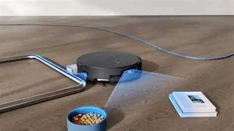
3D dToF LiDAR for Robots: How to Choose a Compact Depth Sensor for Navigation, Obstacle Avoidance, and SLAM
Modern robots do not just need to know that “something” is in the way. They need to know what it is shaped like, how tall it is, how far away it sits, and whether it is inside the robot’s stopping zone. Here’s the deal: a traditional 2D scanner can do a great job building a planar map, but the real world is not a clean CAD drawing. It is full of table edges, glass walls, hanging objects, low-profile obstacles, forklift forks, curbs, cables, pallets, stair edges, and uneven terrain. For AMRs, service robots, drones, security devices, inspection platforms, and embedded vision systems, this is where 3D dToF LiDAR earns its keep. It delivers depth maps and 3D point cloud data in a compact, solid-state package that can fit into real machines, not just lab demos.
This guide walks through how 3D direct Time-of-Flight LiDAR works, how it compares with LDS LiDAR, stereo cameras, structured light, radar, and indirect ToF, and how to choose a compact module for navigation, obstacle avoidance, and SLAM-assisted perception. We will get into the practical specs that matter in the shop: range, accuracy, field of view, resolution, frame rate, outdoor performance, power consumption, interface, SDK support, and mechanical size. Then we will use a compact module such as the DTOF Solid State LiDAR HM-LD1 as a real-world example for robotics integration.
Look, sensor datasheets can make everything sound easy. The hard part is not reading a maximum range number. The hard part is knowing whether that number still means anything when the robot is driving toward a black pallet under skylights, turning near a glass partition, or landing a UAV beside concrete on a bright summer day. That is why this article stays focused on engineering tradeoffs instead of marketing fluff.
In the shop, the best sensor is the one that works with your mechanical envelope, your processor, your control loop, your lighting conditions, and your actual obstacles. A compact 3D dToF module can be a strong fit when you need useful depth data without installing a bulky rotating scanner or relying only on passive cameras.
Table of Contents
- 👉 What Is 3D dToF LiDAR?
- 👉 Why Robots Need 3D Depth Instead of Only 2D Sensing
- 👉 How 3D dToF Works: From Photon Timing to Point Clouds
- 👉 3D dToF vs LDS, Stereo Vision, Structured Light, Radar, and iToF
- 👉 Key Robot Applications: Navigation, Obstacle Avoidance, SLAM, UAVs, and Inspection
- 👉 How to Choose a Compact 3D dToF Sensor
- 👉 Integration Guide for Raspberry Pi, Jetson, PCs, and Embedded Systems
- 👉 Product Example: DTOF Solid State LiDAR HM-LD1
- 👉 Deployment Checklist for Industrial Robot Projects
- 👉 Choosing the Right 3D dToF Module for Your Robot
- 👉 Frequently Asked Questions About 3D dToF
What Is 3D dToF LiDAR?
3D dToF stands for three-dimensional direct Time-of-Flight. It is a depth sensing method that measures distance by calculating how long emitted light takes to travel from the sensor to an object and return to the receiver. In many LiDAR systems, that light is infrared or laser-based. The receiver detects returning photons, and the system converts travel time into distance using the known speed of light.
Definition of dToF
Direct ToF measures the actual travel time of emitted photons. If the sensor knows how long the light took to return, it can calculate the distance to the target. That is different from phase-based indirect Time-of-Flight, where distance is inferred from the phase shift of modulated light. For robotics engineers, the plain-English version is this: dToF is active ranging. It does not depend only on visible texture in the scene, and it can generate measurable distance values even when a conventional camera only sees a flat-looking image.
What Makes It “3D”?
A single-point range sensor gives one distance value. A 3D dToF sensor captures many distance points across a field of view. Each pixel or measurement zone corresponds to a distance value, so the sensor can create a depth image. With calibration parameters, those depth pixels can be projected into real three-dimensional coordinates and represented as a point cloud. That point cloud can then be used by robot software to evaluate surfaces, obstacle zones, object volumes, and open movement corridors.
Why 3D dToF Is Important for Robotics
Robots operate in dynamic, messy, unstructured environments. A compact 3D dToF module can help detect people, furniture, shelves, pallets, walls, curbs, doors, ramps, low obstacles, and suspended objects. For a service robot, the sensor may help identify the height of a chair or table edge. For a UAV, it may assist with altitude hold or landing. For an inspection robot, it may provide real-time perception near bridges, expressways, dams, or industrial equipment. In short, 3D dToF gives machines richer spatial awareness than a single beam or single-plane range sensor.
That extra spatial awareness matters because a robot usually fails at the edge cases, not the perfect demo path. It is easy to drive down a clean hallway. It is harder to detect a black cable on a gray floor, a cart handle sticking out into the aisle, or a pallet fork sitting below the 2D scan plane. A depth image gives the control software more context before the machine makes a bad decision.
Why Robots Need 3D Depth Instead of Only 2D Sensing
2D sensing is still extremely useful, especially for mapping and localization. Many autonomous mobile robots rely on a 2D LiDAR scanner to build a floor-level map and estimate position. But one scan plane only tells part of the story. Warehouses contain pallets, forklift forks, shelves, cables, people, carts, and uneven surfaces. Homes and hospitals contain chairs, table edges, pets, bedding, and moving users. Outdoor environments contain curbs, stones, slopes, stairs, and irregular ground. This is why 3D depth sensing keeps showing up in serious robot designs.
The Limitation of Single-Plane Detection
A single-plane scanner can miss anything that does not intersect its scanning height. If the scanning plane is too high, it may miss small obstacles on the floor. If it is too low, it may miss overhanging objects. A robot may localize correctly on a 2D map while still colliding with something the scanner cannot see. In a busy warehouse or public space, that is not a small issue. It is the kind of issue that damages equipment, scares users, and creates downtime.
Depth Maps for Obstacle Height and Shape
A depth map provides distance values across a scene. Instead of asking only “how far is the nearest object on this plane,” the robot can ask “what is the shape of the object in front of me?” A 3D depth image can help classify whether an object is flat, tall, narrow, low, moving, or partially hidden. That allows the control system to build better local obstacle zones and more conservative motion plans.
3D Data for Safer Autonomous Movement
For indoor AMRs, service robots, security patrol robots, cleaning robots, educational platforms, and inspection robots, 3D sensing can reduce collisions and improve route planning in complex environments. It also supports perception redundancy. A robot may use 2D LiDAR for localization, wheel odometry for motion estimation, RGB cameras for recognition, and 3D dToF for local obstacle geometry. For a broader comparison of ranging technologies, see our guide on LiDAR vs Radar for Robotics.
Here’s the practical point: 2D LiDAR often tells the robot where it is. 3D depth helps the robot understand what it is about to hit. Those are different jobs, and good robot architectures often use both.
How 3D dToF Works: From Photon Timing to Point Clouds
A 3D dToF LiDAR module turns extremely fast photon timing into practical robot perception data. The basic principle is easy to understand, but real performance depends on optics, detector sensitivity, signal processing, calibration, ambient light rejection, and mechanical design. Industrial sensor manufacturers such as SICK also emphasize that sensor selection depends heavily on range, environment, target surface, and application requirements.
Step 1 — Light Emission
⚙️ The module emits short light pulses into the scene. In a solid-state dToF design, there may be no rotating mechanical scanning unit. That can reduce size, simplify integration, and make the sensor more suitable for compact robots, UAVs, and embedded systems where rotating mechanisms are not ideal. The emission pattern, optical field of view, and pulse characteristics all influence how much of the environment can be measured.
Step 2 — Photon Return and Detection
⚙️ When emitted light reaches an object, part of it reflects back toward the receiver. Different surfaces return different signal strengths. White or bright surfaces often return stronger signals than dark surfaces. Flat surfaces facing the sensor typically return more energy than angled surfaces. A receiver array, often based on sensitive detection technology such as SPAD, detects the returning photons and passes timing information to the processing electronics.
Step 3 — Time Measurement
⚙️ The system measures how long the light pulse took to travel to the object and back. The distance is calculated from the speed of light and the measured time of flight. The value must be divided by two because the light travels from the sensor to the target and then back to the receiver. The formula sounds simple, but the implementation is not casual engineering. Light moves fast, so timing precision has to be extremely tight.
Step 4 — Depth Map Generation
⚙️ Each measurement pixel becomes a distance value. These distance values form a two-dimensional depth image where each pixel contains depth instead of color. This output is useful for embedded systems because it can be processed much like an image frame. Developers can threshold distances, create obstacle zones, detect sudden changes, or combine depth with RGB camera data.
Step 5 — Point Cloud Projection
⚙️ With calibration parameters, the depth map can be converted into a 3D point cloud. A point cloud represents real-world coordinates such as X, Y, and Z. Robotics software can use point clouds for obstacle avoidance, local mapping, object detection, volume measurement, docking, or environmental modeling. For ROS-based systems, point cloud data may be transformed into the robot base coordinate frame and fused with odometry, IMU, or other sensors.
Key Factors That Affect Measurement Quality
Measurement quality depends on ambient light intensity, target reflectivity, surface angle, sensor optics, integration time, frame rate, signal processing, multipath reflections, sunlight interference, and distance to the target. Strong sunlight can add background noise. Dark surfaces may return weak signals. Transparent or reflective materials can create difficult measurement conditions. Engineers should validate performance with the real materials, lighting, mounting height, and movement speed expected in the final application.
In the shop, this is where prototype testing pays for itself. Do not test only on white cardboard at two meters indoors. Test on black rubber, stainless steel, glass, dusty plastic, safety vests, shrink wrap, concrete, wet pavement, and whatever ugly surfaces your robot will actually face.
3D dToF vs LDS, Stereo Vision, Structured Light, Radar, and iToF
Choosing a robot depth sensor is not simply a matter of selecting the longest advertised range. Different sensing technologies produce different data and fail in different ways. 3D dToF is especially valuable when compact depth imaging and direct distance measurement are required, but it may also be combined with other sensors. If you are still comparing scanner types, read our detailed guide on how to choose the best LiDAR scanner.
| Technology | Strengths | Limitations | Best Fit |
|---|---|---|---|
| 3D dToF LiDAR | Direct distance measurement, depth maps, point clouds, compact solid-state designs, useful in robotics | Performance depends on sunlight, reflectivity, optics, and range | Obstacle avoidance, robot vision, UAV sensing, embedded depth perception |
| LDS / 2D LiDAR | Strong 2D mapping, mature SLAM ecosystem, long planar scan range | Limited vertical information; may miss obstacles outside scan plane | Robot vacuum mapping, AMR localization, planar navigation |
| Stereo Vision | Rich visual data, passive sensing, useful for AI vision | Needs texture and lighting; depth accuracy can degrade on blank or reflective surfaces | Visual perception, object recognition, AI inspection |
| Structured Light | High short-range detail, good for controlled indoor environments | Often weaker outdoors or under strong ambient light | Face recognition, close-range scanning, indoor measurement |
| Radar | Robust in dust, fog, rain, and poor visibility | Lower spatial resolution than optical depth sensors | Outdoor vehicles, harsh environments, speed detection |
| iToF | Depth imaging with phase-based measurement, common in cameras | Can face ambiguity and multipath issues depending on modulation and range | Consumer depth cameras, indoor human-machine interaction |
3D dToF vs LDS LiDAR
LDS LiDAR is often a rotating 2D scanning LiDAR used in robot vacuums and mobile robots. It is excellent for floor-level mapping and localization, but it does not produce a dense 3D depth image. A 3D dToF sensor can complement LDS by adding vertical perception, obstacle height information, and near-field scene geometry. In some compact systems, 3D dToF may also replace certain scanning functions when the required task is local obstacle detection rather than full planar mapping.
3D dToF vs Stereo Cameras
Stereo cameras infer depth from image disparity between two lenses. They provide rich visual information and are useful for AI perception, but they often need adequate texture and lighting. Blank walls, repetitive patterns, darkness, glare, and reflective surfaces can reduce stereo reliability. 3D dToF actively measures distance and can work in conditions where passive stereo is less reliable, though it still must handle sunlight, surface reflectivity, and optical limitations.
3D dToF vs Structured Light
Structured light projects a known pattern and observes how that pattern deforms on objects. It can deliver fine short-range detail in controlled indoor environments, making it useful for close-range scanning and human-machine interaction. But outdoor sunlight can overpower the projected pattern. For robots that need operation in mixed lighting or outdoor daytime conditions, dToF specifications should be evaluated carefully against the required distance and target material.
3D dToF vs Radar
Radar is strong in harsh weather, dust, fog, rain, and poor visibility. It can also measure velocity in many implementations. However, radar usually provides lower spatial resolution than optical depth sensors. For robotics, radar and 3D dToF can be complementary: radar may detect objects in difficult weather, while 3D dToF provides more detailed short-to-medium-range scene geometry for obstacle avoidance and local navigation.
3D dToF vs iToF
Indirect ToF uses phase shift measurements from modulated light. It is common in compact depth cameras and can work well indoors, especially at short-to-medium distances. Direct ToF measures travel time more directly. In robot applications where timing-based ranging, outdoor potential, and clean distance interpretation are important, dToF is often attractive. That does not mean iToF is bad. It means you need to match the measurement method to the job.
Key Robot Applications: Navigation, Obstacle Avoidance, SLAM, UAVs, and Inspection
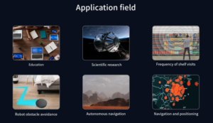
Obstacle Avoidance for Mobile Robots
3D dToF helps mobile robots detect obstacles with height and shape. In a warehouse, this may include pallets, carts, forklift forks, shelving edges, or people standing near an aisle. In hospitals and hotels, it may include beds, chairs, carts, users, and partially open doors. In homes, it may include pet bowls, toys, shoes, cables, and furniture legs. Instead of treating every obstacle as a flat range point, the robot can evaluate the local scene as a depth field and make safer movement decisions.
Navigation and Local Path Planning
A 3D depth sensor can provide local obstacle data for path planning. The robot can use the depth map or point cloud to create a local cost map, marking dangerous zones and free space. This supports safer motion through narrow corridors, shelves, desks, crowds, and dynamic obstacles. The sensor does not replace all navigation software, but it gives the navigation stack richer geometric information for short-range decisions.
SLAM Assistance and 3D Environmental Perception
A 3D dToF sensor may not automatically perform SLAM by itself. Instead, it provides depth data that can be used by SLAM algorithms. Actual SLAM performance depends on software, synchronization, calibration, IMU data, odometry, computing platform, and environmental structure. In many systems, dToF is used for local perception and obstacle avoidance while another sensor such as 2D LiDAR, visual odometry, wheel odometry, GNSS, or RTK contributes to global localization.
UAV Altitude Hold and Terrain Following
For drones, compact size and low weight are critical. A lightweight 3D dToF module can support altitude hold, landing assistance, obstacle detection, and terrain following. UAVs benefit from depth sensors that can be mounted without significantly reducing flight time. Engineers must still consider vibration, attitude changes, sunlight, frame rate, integration latency, and the relationship between sensor field of view and flight direction.
Inspection Robots for Bridges, Dams, Expressways, and Industrial Sites
Inspection robots often operate near structures that are difficult or unsafe for people to approach. A compact dToF LiDAR module can help measure distances to surfaces, detect obstacles, and support inspection navigation. The HM-LD1 product description notes accurate ranging even from a long distance of 8 meters on a clear summer day under approximately 80,000 lux conditions. For outdoor robots, 3D perception is often combined with GNSS, IMU, odometry, or high-precision positioning methods such as Real-Time Kinematic positioning.
Security, Presence Detection, and Zone Intrusion Monitoring
Security systems can use 3D depth to detect whether a person or object enters a defined zone. Unlike simple 2D motion detection, depth sensing can add distance, height, and volume information. This may reduce false triggers and improve event classification. For smart access control, industrial safety zones, perimeter monitoring, and presence detection, compact 3D dToF sensors can provide an efficient perception layer.
How to Choose a Compact 3D dToF Sensor
Selecting a 3D dToF sensor requires more than comparing headline range. Engineers should evaluate how the module performs in the real application environment, how it outputs data, how it mounts mechanically, and how easily it integrates with the robot computing platform. The following criteria are practical for robotics teams, UAV developers, embedded system integrators, and purchasing teams.
1. Ranging Capability: Indoor vs Outdoor
✅ Indoor range is usually longer because ambient light is lower. Outdoor range can be shorter because sunlight adds background noise. Buyers should check whether the advertised range is measured indoors, outdoors, at night, under sunlight, or with high-reflectivity targets. The HM-LD1 lists indoor ranging capability of 0.5 to 25 m and outdoor ranging capability of 0.2 to 8 m. Product text also describes support for 0 to 25 m in indoor or nighttime conditions and 0 to 8 m in outdoor daytime environments. Before final design freeze, confirm the latest minimum range definition and test conditions.
2. Ranging Accuracy
✅ Accuracy matters for obstacle avoidance, volume measurement, docking, distance detection, and manipulation. The HM-LD1 lists ranging accuracy of ±3 cm. In real deployment, accuracy may vary with distance, target surface, sunlight, surface angle, filtering settings, and motion. For safety-related functions, accuracy should be tested at the specific distances that matter most, not only at the maximum range.
3. Field of View
✅ The HM-LD1 lists a 60° horizontal by 45° vertical field of view. A wider field of view captures more of the environment, which can be helpful for obstacle avoidance and landing assistance. However, field of view must be evaluated with resolution. If the pixel count is fixed, a wider field spreads measurements across a larger angle. Engineers should simulate or physically test the mounting height and tilt angle to ensure the sensor covers the robot’s blind zones.
4. Resolution
✅ The HM-LD1 lists 40 × 30 resolution, which equals 1,200 measurement points per frame. This can be practical for compact obstacle detection, depth awareness, presence detection, and distance zone monitoring. It is not the same as a high-density 3D scanning LiDAR used for detailed mapping. Low-resolution depth can be sufficient for detecting people, walls, pallets, or large obstacles, while complex object classification and detailed 3D modeling may require higher resolution or sensor fusion.
5. Frame Rate
✅ The HM-LD1 lists a frame rate of 10 fps. This may be suitable for many low-to-medium-speed robots, static monitoring devices, slow UAV maneuvers, and embedded obstacle detection. Faster robots may require higher frame rates, predictive filtering, additional sensors, or larger safety margins. Frame rate should always be evaluated together with robot velocity, braking distance, processing delay, and control loop latency.
6. Interface Options
✅ The HM-LD1 supports UART, UDP, and UVC. UART is useful for simple embedded integration with microcontrollers or flight controllers. UDP is practical for network-based data transmission to Linux systems, robot computers, or industrial PCs. UVC can simplify PC or embedded development by enabling a camera-like USB video class workflow. Multiple interface options reduce integration risk because teams can choose the architecture that best matches their hardware and software stack.
7. SDK and Platform Support
✅ SDK support is critical for rapid development. HM-LD1 support is described for x86 Windows, x86 Linux, and ARM Linux. This matters for teams using Windows test stations, Linux industrial PCs, Raspberry Pi platforms, Jetson-class AI computers, or other embedded Linux systems. Good SDK availability can shorten the path from prototype to field test by reducing driver development work.
8. Power Consumption
✅ The HM-LD1 lists power consumption of 1.2 W. Low power consumption is especially important for drones, battery-powered robots, wearable systems, mobile security devices, and distributed multi-sensor architectures. Power affects runtime, heat generation, battery sizing, and enclosure design. Engineers should also consider startup behavior, cable losses, and host platform power capacity.
9. Mechanical Size and Weight
✅ The official table lists the HM-LD1 dimension as 43.5 mm × 30 mm × 26.5 mm and weight as 28 g. Product body text also emphasizes compact and lightweight housing for integration into autonomous mobile robots with limited sensor space and drones where weight affects flight distance. Use the table value as the main specification and check the latest mechanical drawing before final enclosure design, gasket design, or optical window placement.
10. Operating Temperature
✅ The HM-LD1 lists an operating temperature range from -20 ℃ to 60 ℃. This is important for industrial robots, outdoor inspection devices, warehouses, UAVs, and mobile platforms that may experience temperature variation. Thermal testing should include expected enclosure conditions, solar exposure, processor heat, airflow, and duty cycle.
Integration Guide for Raspberry Pi, Jetson, PCs, and Embedded Systems
Typical Data Pipeline
⚙️ A typical 3D dToF pipeline begins when the sensor captures a depth frame. The module then outputs a depth map or point cloud through UART, UDP, or UVC. The host receives the data, filters noise and invalid points, converts depth into obstacle zones or 3D coordinates, and passes the resulting information to the navigation stack, safety logic, mapping software, or application layer. The exact architecture depends on whether the robot needs raw depth, point clouds, simplified distance zones, or fused perception.
Raspberry Pi Integration
Raspberry Pi platforms are common in education, prototyping, lightweight robotics, and embedded vision. ARM Linux SDK support helps reduce integration time. A compact, low-power 3D dToF module can be useful for small robot platforms where space and battery capacity are limited. Developers should evaluate CPU load, data bandwidth, interface stability, and whether the Pi is also running navigation, camera processing, networking, or user interface tasks.
Jetson Integration
Jetson-class platforms are often used when robots combine depth sensing with AI inference, RGB cameras, object detection, or ROS pipelines. A 3D dToF module can provide geometry while neural networks provide classification. For example, the robot may use RGB vision to identify a pallet or person while dToF provides distance and obstacle volume. Developers should consider synchronization, calibration, point cloud processing, coordinate transforms, and GPU or CPU workload.
Industrial PC Integration
Warehouse AMRs, security platforms, and inspection robots often use x86 Linux or Windows industrial PCs. UDP or UVC can simplify deployment depending on the system architecture. UDP may be suitable for networked data flow, while UVC may fit applications that benefit from camera-style input. Industrial teams should also check cable length, connector robustness, EMC behavior, enclosure sealing, and long-term supply requirements.
ROS and Robotics Middleware Considerations
Even when native ROS support is not claimed, robotics developers typically need timestamped frames, calibration parameters, coordinate transforms, depth image topics, point cloud topics, frame synchronization, and extrinsic calibration to the robot base frame. A sensor that outputs usable depth or point cloud data through standard interfaces can be wrapped into a middleware pipeline, but the engineering team must still validate latency, transform accuracy, and failure handling.
Mounting and Calibration
Mounting determines what the sensor can see. Engineers should consider mounting height, tilt angle, blind zones, field of view coverage, vibration isolation, lens cleanliness, sunlight direction, sensor protection windows, and coordinate calibration. A protective window may be necessary in industrial environments, but it must not degrade optical performance. For UAVs, vibration and attitude changes require special attention. For AMRs, the sensor should cover the stopping zone and expected obstacle heights.
Product Example: DTOF Solid State LiDAR HM-LD1
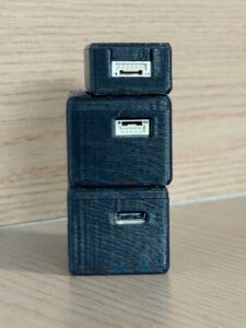
The DTOF Solid State LiDAR HM-LD1 is a compact 3D dToF depth sensor designed for robotic perception, obstacle avoidance, navigation assistance, UAV sensing, and embedded 3D vision development. It is based on SPAD dToF technology and delivers real-time depth images and 3D point cloud data for environmental perception. Typical applications include distance detection, autonomous navigation, smart inspection, robotic vision development, UAV altitude hold, terrain following, autofocus support, user presence detection, object recognition, volume measurement, and zone intrusion monitoring.
HM-LD1 is designed for integration into PCs, Raspberry Pi platforms, flight controllers, and embedded systems through UART, UDP, and UVC interfaces. SDK support for x86 Windows, x86 Linux, and ARM Linux helps shorten development time for robotics teams moving from prototype to deployment. Its compact housing and 28 g weight make it practical for robots with limited sensor space and UAVs where every gram affects flight time and payload capacity.
View Product Details & Pricing ➔
HM-LD1 Dimensions and Ranging Specifications
| Specification | DTOF Solid State LiDAR HM-LD1 |
|---|---|
| Dimension | 43.5 mm × 30 mm × 26.5 mm |
| Ranging Capability | Indoor: 0.5–25 m; Outdoor: 0.2–8 m |
| Ranging Accuracy | ±3 cm |
| Field of View | 60° horizontal × 45° vertical |
| Weight | 28 g |
HM-LD1 Product Details
| Specification | DTOF Solid State LiDAR HM-LD1 |
|---|---|
| Resolution | 40 × 30 |
| Frame Rate | 10 fps |
| Interface | UART / UDP / UVC |
| Operating Temperature | -20 ℃ to 60 ℃ |
| Power Consumption | 1.2 W |
Depth Map and Point Cloud Output
HM-LD1 can provide depth images and point cloud data. This is important because not every application needs the same output. Some robots only need zone distance for obstacle avoidance. Others need 3D coordinates for mapping, robot vision, inspection, object measurement, or environmental modeling. Having access to depth and point cloud data gives developers more flexibility during prototyping and deployment.
Compact and Lightweight for Space-Constrained Robots
The module is listed at 28 g and uses a compact housing. This is valuable for UAVs where sensor weight affects flight distance and for autonomous mobile robots where front sensor pods may have limited space. Compact solid-state construction also helps teams integrate depth perception into security devices, smart cameras, inspection tools, and embedded platforms without the mechanical complexity of larger rotating scanners.
Outdoor and Indoor Ranging
The HM-LD1 lists indoor ranging capability from 0.5 to 25 m and outdoor ranging capability from 0.2 to 8 m. Product details also describe useful outdoor measurement at long distance under clear summer daylight conditions. Outdoor performance should always be validated in the final environment because sunlight intensity, object material, distance, and target angle all influence ranging quality.
Multi-Platform Development Support
MRP offers SDKs for x86 Windows, x86 Linux, and ARM Linux. This is helpful for development teams working across test PCs, Raspberry Pi boards, Jetson-class systems, embedded Linux computers, and industrial PCs. Multi-platform support can reduce software risk, especially when a project must move from a lab prototype to a deployable robot product.
Download Product Brochure
Request Quote / Add to Cart
Deployment Checklist for Industrial Robot Projects
Before purchasing or integrating a 3D dToF module, engineering teams should define measurable requirements. A sensor that works well in a demonstration may still need validation against the final robot speed, braking distance, lighting, target materials, mounting position, and software architecture.
- ✅ Define the required indoor and outdoor detection range.
- ✅ Confirm the minimum detection distance for close obstacles.
- ✅ Check whether the field of view covers the robot’s blind zones.
- ✅ Match frame rate to robot speed and stopping distance.
- ✅ Verify depth accuracy at the distances that matter most.
- ✅ Test target materials: black, white, reflective, transparent, angled, and irregular surfaces.
- ✅ Validate performance under sunlight, indoor lighting, and nighttime conditions.
- ✅ Confirm interface compatibility: UART, UDP, UVC, USB adapter, Ethernet, or serial pipeline.
- ✅ Check SDK support for Windows, Linux, ARM Linux, or the target embedded OS.
- ✅ Plan mechanical mounting, vibration control, lens protection, and heat dissipation.
- ✅ Calibrate sensor pose relative to the robot base frame.
- ✅ Decide whether the robot needs depth map data, point cloud data, or simplified obstacle zones.
- ✅ Integrate with odometry, IMU, camera, GNSS, RTK, or 2D LiDAR if needed.
- ✅ Run field tests before final enclosure and mass production.
Safety Margin and Stopping Distance
Detection range must be evaluated against robot velocity, braking distance, control latency, frame rate, and processing delay. A sensor may detect an obstacle, but if the robot cannot process the data and stop in time, the system is not safe enough. Engineers should calculate conservative safety margins and validate them with real motion tests.
Environmental Validation
Environmental validation should include sunlight, indoor lighting, night operation, dust, vibration, temperature, target reflectivity, and optical window contamination. For outdoor inspection or UAV applications, testing should include changing sun angles and different surface materials. For industrial AMRs, testing should include pallets, metal racks, black rubber, reflective safety vests, and moving people.
Sensor Fusion Strategy
Many industrial systems use multiple sensors. A 3D dToF module can be combined with 2D LiDAR, RGB cameras, IMU, wheel odometry, ultrasonic sensors, radar, GNSS, or RTK depending on the robot type. The goal is not to use more sensors for complexity’s sake, but to cover failure modes and improve reliability in the actual operating environment.
Choosing the Right 3D dToF Module for Your Robot
Choosing the best 3D dToF LiDAR is not only about maximum range. For real robot deployment, the more important questions are: Can the sensor detect the obstacles your robot actually encounters? Does the field of view cover the danger zone? Is the frame rate suitable for your robot speed? Can the module run on your embedded platform? Does it provide the data format your software stack needs? Is the housing small and light enough for your robot or UAV design?
For teams developing compact robots, UAVs, embedded vision systems, inspection devices, or security monitoring products, the DTOF Solid State LiDAR HM-LD1 provides a practical balance of compact size, low weight, depth output, point cloud capability, UART / UDP / UVC interfaces, and multi-platform SDK support.
Look, no single sensor solves every robotics problem. But a compact 3D dToF module can be a smart piece of the perception stack when the project needs real depth, reasonable integration effort, and a form factor that does not fight the mechanical design. The teams that get the best results usually define the operating envelope early, test under ugly real-world conditions, and build enough safety margin into the software and mechanical layout.
Evaluate HM-LD1 for Your Robot or UAV Project
Review the specifications, download the brochure, or contact MyRobotProject for integration support and OEM/ODM customization options.
HM-LD1 dToF Solid-State LiDAR: Compact Depth Sensing for UAVs & Robotics
Frequently Asked Questions About 3D dToF
Is 3D dToF better than LDS LiDAR for robot vacuums and mobile robots?
Can a small and affordable 3D ToF sensor be integrated into Raspberry Pi, Jetson, or embedded systems?
How do 3D ToF sensors create depth maps or 3D models, and are they reliable outdoors?
What is the difference between dToF and iToF?
Can 3D dToF LiDAR be used for SLAM?
What resolution is enough for robot obstacle avoidance?
How important is field of view for a 3D dToF robot sensor?
Why is outdoor range usually shorter than indoor range for 3D dToF sensors?
What interfaces should I look for in a 3D dToF LiDAR module?
Is 3D dToF suitable for drones and UAVs?
📚 References & Further Reading
- Industry Standard: SICK industrial sensor selection resources
- Industry Standard: Real-Time Kinematic positioning overview
- Related Guide: LiDAR vs Radar for Robotics
- Related Guide: How to Choose the Best LiDAR Scanner
- Product Resource: DTOF Solid State LiDAR HM-LD1 Product Page
- Product Resource: DTOF SSL HM-LD1 Product Brochure






