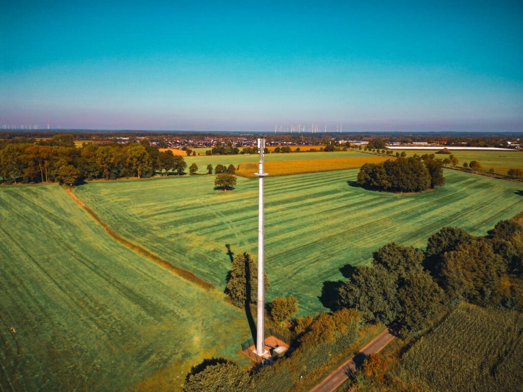
Lidar Drone Sensor Buying Guide: Choose Reliable 3D Obstacle Avoidance for UAVs
Here’s the deal: a lidar drone sensor can give an unmanned aerial vehicle the depth information it needs to spot nearby structures, estimate obstacle distance, follow terrain, and support collision-avoidance decisions. But a good-looking maximum-range number on a product page does not automatically mean dependable performance in the air. Direct sunlight, target reflectivity, field of view, mounting angle, airframe vibration, vehicle speed, processing latency, and navigation-software behavior all affect whether the UAV sees an obstacle early enough to do something useful about it.
This guide lays out a practical way to evaluate compact 3D lidar for UAV perception without getting hung up on range alone. It covers direct time-of-flight technology, outdoor operation, depth resolution, frame rate, accuracy, payload impact, power, interfaces, point-cloud processing, mounting, calibration, and flight testing. It also reviews the HM-LD1-NV and HM-LD1 solid-state dToF modules using their published specifications, giving engineering and procurement teams a more defensible way to build a shortlist for drone obstacle detection and autonomous navigation work.
Engineering note: A lidar module is a perception component, not a complete collision-avoidance system. Safe obstacle avoidance also depends on directional coverage, calibration, state estimation, software, flight dynamics, braking distance, redundancy, failure handling, and real-world validation.
Table of Contents
- 👉 Quick Selection Checklist
- 👉 What Is a Lidar Drone Sensor?
- 👉 How 3D dToF Lidar Works on a UAV
- 👉 Drone Obstacle-Avoidance Requirements
- 👉 Specifications That Matter
- 👉 Outdoor and Direct-Sunlight Performance
- 👉 Range, Speed, Frame Rate, and Reaction Distance
- 👉 Field of View, Resolution, and Coverage
- 👉 Payload, Power, and Mechanical Integration
- 👉 Interfaces, SDKs, and Software Integration
- 👉 Mounting and Calibration
- 👉 HM-LD1-NV and HM-LD1 Specifications
- 👉 Application-Fit Recommendations
- 👉 Bench, Ground, and Flight Validation
- 👉 Procurement Checklist
- 👉 Frequently Asked Questions
- 👉 Selection Recommendations
Quick Selection Checklist for a Lidar Drone Sensor
Look, the right UAV lidar has to be matched to the actual mission. Screening a module by one headline range figure is how expensive redesigns get started. Before ordering samples, put the following requirements on paper and compare every candidate against the same list:
- ✅ Outdoor range under a stated illumination level, not just the best indoor maximum.
- ✅ Minimum range for close obstacle detection, landing, docking, and inspection standoff control.
- ✅ Target assumptions, including material, reflectivity, physical size, incidence angle, and movement.
- ✅ Horizontal and vertical field of view relative to vehicle pitch, roll, yaw, and all permitted flight directions.
- ✅ Depth resolution and angular sampling, especially if poles, branches, fence wire, or utility cables matter.
- ✅ Frame rate and end-to-end latency, including transport, filtering, planning, autopilot response, and vehicle dynamics.
- ✅ Accuracy, repeatability, invalid-point behavior, and confidence information.
- ✅ Installed weight, including cables, brackets, fasteners, enclosure, and optical window.
- ✅ Power requirements, startup behavior, voltage compatibility, heat generation, and conversion losses.
- ✅ Interfaces and SDKs that work with the selected flight controller or companion computer.
- ✅ Operating temperature, vibration tolerance, and environmental protection.
- ✅ Eye-safety documentation, technical support, production availability, and lifecycle information.
A compact module such as HM-LD1-NV is most relevant when a UAV needs directional, short- to medium-range 3D perception without a large payload or electrical burden. Its published specifications include 40 × 30 depth resolution, 10 fps output, ±3 cm ranging accuracy, a 60° × 45° field of view, 28 g weight, and outdoor ranging from 0.2 to 8 m at 80 klux. That is a useful starting point. It is not a substitute for testing the required obstacle materials, weather exposure, flight envelope, mounting arrangement, and complete perception stack.
What Is a Lidar Drone Sensor?
Definition and Role in UAV Perception
A lidar drone sensor measures distance by emitting light and analyzing the returned optical signal. A single-point rangefinder reports one distance in one direction. A 3D lidar module measures multiple directions across a scene, producing data that can be arranged as a depth map or projected into a point cloud representing nearby geometry.
On a UAV, that direct depth information can support forward obstacle detection, side or rear awareness, upward detection beneath roofs and tree canopies, downward altitude assistance, terrain following, landing-zone assessment, inspection standoff control, and local navigation in GPS-denied areas. Which jobs the sensor can perform depends on its orientation, angular coverage, range, sampling density, software, and the way the aircraft moves.
Sensor Versus Complete Obstacle-Avoidance System
Here’s an important distinction: the sensor measures depth, but it does not independently decide what the aircraft should do. A working drone obstacle-avoidance architecture normally includes the lidar module, timestamped data transport, a flight controller or companion computer, intrinsic and extrinsic calibration, attitude compensation, point filtering, obstacle extraction, a local map, path planning, autopilot commands, and defined failsafe behavior.
In the shop, we would never sign off on collision avoidance just because the depth image looked good on a laptop. If an obstacle sits outside the field of view, produces a weak return, gets removed by a filter, or appears too late for the aircraft to stop, the lidar module cannot solve that problem by itself.
Lidar Compared with Cameras, Ultrasonic Sensors, and Radar
- ✅ Monocular cameras provide rich visual information, but depth may depend on inference, vehicle motion, lighting, scene texture, and processing capacity.
- ✅ Stereo cameras calculate depth from disparity and may struggle with low-texture surfaces, darkness, glare, or repetitive visual patterns.
- ✅ Ultrasonic sensors are economical for short-range measurements but generally provide broad beams and limited spatial detail.
- ✅ Radar can perform well in some weather and long-range conditions, although angular separation and small-object detection depend on frequency, antenna design, and processing.
- ✅ Lidar supplies direct geometric distance measurements with useful angular structure, but performance still depends on ambient light, reflectivity, atmosphere, optical design, and sample density.
Industrial UAVs often use sensor fusion instead of asking one device to do everything. Cameras can add semantic detail, an IMU describes attitude and motion, GNSS provides broader positioning, and lidar contributes local geometric awareness. That division of labor usually makes for a stronger system.
How 3D dToF Lidar Works on a UAV
Direct Time-of-Flight Measurement
Direct time of flight, usually shortened to dToF, estimates distance from the round-trip travel time of an emitted optical pulse. The sensor sends out light, detects photons reflected from a target, and measures elapsed time. Distance is calculated by multiplying the measured time by the speed of light and dividing by two. The division accounts for the trip to the target and the return trip to the receiver.
According to the supplied product information, HM-LD1-NV uses 940 nm VCSEL illumination with a high-sensitivity SPAD-based receiver. A VCSEL is a vertical-cavity surface-emitting laser used as the illumination source. A SPAD is a single-photon avalanche diode designed to respond to weak optical returns. Engineers researching the underlying semiconductor technology can review resources from onsemi. That link is provided for general technical context and does not establish that a specific onsemi component is used in HM-LD1-NV.
From a Depth Map to a Drone Point Cloud
A 40 × 30 resolution means the module can report a grid containing as many as 1,200 depth locations per frame before invalid samples, confidence filtering, and other processing are considered. Using the sensor’s calibrated optical model, software can project that depth map into three-dimensional coordinates. The resulting drone point cloud can feed occupancy grids, nearest-obstacle calculations, terrain profiles, ground-plane estimation, corridor detection, object clustering, and local path planning.
At a nominal 10 fps, the module supplies up to ten depth frames per second. That does not mean every sample will always be valid, and it does not mean the aircraft receives a new navigation command every 100 milliseconds. Interface transfer, buffering, filtering, mapping, planning, and autopilot behavior all add time.
Why Solid-State Construction Matters
A compact solid-state lidar is usually easier to package on a small UAV than a large mechanically scanning unit. Potential system-level benefits include low mass, compact dimensions, fixed geometry, and no rotating scanner assembly. The tradeoff is coverage. One fixed sensor sees only its specified field of view. It cannot deliver complete spherical or 360-degree awareness unless the design adds more sensors, uses aircraft motion, or incorporates another perception technology.
Define the Drone Obstacle-Avoidance Requirement First
Start with the Mission Profile
Before comparing modules, document maximum and normal airspeed, indoor or outdoor use, expected illumination, the smallest required obstacle, obstacle materials, minimum clearance, flight altitude, sensing direction, weather exposure, available compute, payload allowance, and applicable safety requirements. A slow inspection aircraft moving through a warehouse needs a very different sensing envelope from an agricultural UAV crossing an open field.
A forward-facing outdoor lidar selected to detect buildings should not automatically be expected to see thin wires, provide downward terrain following, or protect the aircraft during sideways movement. Each required behavior needs its own measurable performance target.
Define the Obstacles That Must Be Detected
| Obstacle category | Examples | Main detection challenge |
|---|---|---|
| Large planar objects | Walls, buildings, containers | Incidence angle, sunlight, and edge coverage |
| Natural objects | Trees, branches, foliage | Irregular geometry and partial returns |
| Thin objects | Wires, cables, narrow poles | Sparse angular sampling and weak returns |
| Dark surfaces | Black paint, tires, dark fabric | Low optical return |
| Reflective or transparent surfaces | Glass, polished metal, water | Redirected returns, multipath, or transmission |
| Moving objects | People, vehicles, machinery | Tracking and total system latency |
| Ground features | Slopes, ditches, crop canopy | Sensor angle and ground classification |
Thin wires and transparent materials belong in the high-risk category and need dedicated testing. Reliable detection cannot be inferred from maximum range. For additional application context, read this guide to compact dToF lidar for smarter UAV obstacle avoidance.
Choose a Coverage Architecture
Common layouts include forward-only sensing, forward-plus-downward sensing, and multi-directional arrays. A 60° horizontal by 45° vertical field of view can provide useful directional coverage, but it does not cover the entire space around the aircraft. Sensor quantity and orientation should come from airframe geometry, permitted flight directions, yaw behavior, expected attitude, and a documented blind-zone analysis.
Lidar Drone Sensor Specifications That Matter
Minimum and Maximum Range
Maximum range determines the earliest possible detection point. Minimum range defines the near-field blind zone and can affect landing, docking, close inspection, and final obstacle clearance. HM-LD1-NV publishes an indoor range of 0.5 to 25 m and an outdoor range of 0.2 to 8 m at 80 klux. The 25 m number should never be presented as a generalized outdoor range.
Accuracy, Precision, and Repeatability
Accuracy is closeness to the true distance. Precision, or repeatability, is consistency across repeated measurements. Resolution may refer to represented distance increments or to spatial sampling density. Bias is a systematic offset, while noise is frame-to-frame variation. HM-LD1-NV lists ±3 cm ranging accuracy, but one tolerance cannot describe every distance, surface, angle, sunlight level, temperature, or confidence condition. Ask for the test method and review the full error distribution.
Depth Resolution and Angular Sampling
HM-LD1-NV has a 40 × 30 depth grid across a 60° × 45° field of view. A simplified average works out to roughly 1.5 degrees of sampling per axis. Actual ray centers, optical distortion, calibration, and usable performance near the edges must be confirmed from technical data. As range increases, the physical gap between adjacent rays gets wider, which makes narrow-object detection more difficult.
Field of View
Evaluate horizontal and vertical coverage separately. A wider FOV sees more space but spreads the available depth samples over a larger angular area. Check full versus effective FOV, edge accuracy, overlap between sensors, airframe occlusion, propeller intrusion, and vertical coverage during acceleration, pitch changes, and braking.
Frame Rate and Latency
The published 10 fps frame rate corresponds to nominal frame intervals of about 100 ms. Frame rate is not the same thing as end-to-end reaction latency. Acquisition, serialization, interface transfer, buffering, timestamp alignment, filtering, obstacle extraction, planning, command transmission, actuator response, and airframe dynamics all count.
Wavelength, Eye Safety, and Temperature
HM-LD1-NV uses 940 nm VCSEL illumination and is described as meeting Class 1 eye safety. Buyers should request the relevant certificate, test report, standard edition, operating conditions, and final-product compliance requirements. The listed operating temperature is −20°C to 60°C. Keep in mind that enclosure temperature can run much hotter than ambient because of solar loading, nearby processors, limited airflow, or a powered aircraft sitting on the ground.
Outdoor and Direct-Sunlight Performance
Why Ambient Light Matters
Sunlight adds background optical energy around the receiver’s operating band. The sensor has to separate the desired reflected pulse from background photons and noise. Outdoor capability therefore depends on receiver sensitivity, optical filtering, timing, signal processing, target return strength, and the condition of the optical surface.
HM-LD1-NV’s published outdoor specification is helpful because it names an illumination condition: 0.2 to 8 m at 80 klux. Still, 80 klux is a test condition, not a blanket guarantee that every object will be detected at 8 m.
Reflectivity and Incidence Angle
A large, light-colored, diffuse wall will usually send more optical energy back to the receiver than dark fabric or black paint. A surface angled away from the sensor may direct much of the return somewhere else. A credible test program should include white and black matte targets, foliage, weathered wood, concrete, dark clothing, metal at several angles, glass, wet surfaces, reflective tape, small branches, and cables.
Rain, Fog, Dust, and Optical Contamination
Rain, fog, and airborne dust can scatter or attenuate the outgoing and returning light. Condensation, mud, fingerprints, and scratches on an optical window can also reduce valid range or create misleading measurements. Unless the supplier provides ingress-protection and environmental data, treat the lidar as a component that may need a properly engineered enclosure.
Range, Flight Speed, Frame Rate, and Reaction Distance
Calculate the Full Reaction and Stopping Distance
Required detection distance has to include the distance traveled during total system latency, the distance needed to brake or divert, a control margin, and the final required obstacle clearance. Latency distance is simply aircraft speed multiplied by measured total latency.
At 5 m/s, a total latency of 200 ms means the aircraft travels about 1 m before accounting for the additional distance required for the maneuver to take effect. That is an engineering example, not a claim about HM-LD1-NV system latency.
Total latency should include frame acquisition, data serialization, interface transport, buffering, timestamp alignment, filtering, point-cloud processing, obstacle classification, path planning, autopilot acceptance, motor response, and vehicle dynamics. In the shop, measure it end to end. Do not build the calculation from optimistic estimates taken from separate datasheets.
What 10 fps Means in Practice
A 10 fps sensor produces frames at nominal 100 ms intervals. The age of the newest usable measurement can vary because of acquisition timing, queues, dropped frames, host scheduling, and processing load. Software should monitor timestamps, detect stale data, limit buffer depth, and define what happens if a frame or connection disappears.
Ten frames per second may be suitable for useful local perception on a slow UAV when range, processing, and vehicle dynamics are designed around that update rate. Faster flight, aggressive maneuvering, and thin-object detection require much closer review of range, spatial resolution, latency, and stopping capability.
Attitude and Motion Compensation
Pitch, roll, and yaw rotate the sensor’s viewing frustum. During acceleration, a forward-mounted lidar may point toward the ground. During turns, it can point away from the intended corridor. Depth measurements should be transformed into the appropriate body, odometry, or world frame using synchronized IMU and attitude information. Timing or calibration errors can make stationary obstacles appear displaced or even moving.
Field of View, Resolution, and Blind-Zone Planning
Create a Three-Dimensional Coverage Model
Model each sensor frustum in CAD and overlay the propellers, arms, landing gear, payloads, enclosure edges, gimbals, cables, and expected attitude envelope. This is basic integration work, but it catches a surprising number of problems before hardware is cut. It can expose self-returns, blocked rays, and blind areas that are hard to notice on a bench.
Single-Sensor Versus Multi-Sensor Layouts
A single forward-facing HM-LD1-NV may support directional obstacle detection, but it cannot see behind the aircraft or provide full surrounding coverage. Adding modules improves coverage while increasing mass, wiring, electrical load, calibration effort, bandwidth, compute demand, and cost. If uninterrupted directional coverage is required, adjacent fields of view may need deliberate overlap. Also test whether multiple active optical sensors interfere with one another in the intended mounting geometry.
Thin Obstacles and Sparse Returns
For cables and small branches, sampling density may matter more than maximum range. The physical gap between neighboring depth rays grows as distance increases. A narrow object can sit between samples or generate too few returns to survive clustering and noise filtering. Define a minimum obstacle cross-section and a required detection probability, then move the target through the complete FOV rather than testing only at the center.
Payload, Power, and Mechanical Integration
Use Installed Mass, Not Bare Module Mass
HM-LD1-NV is listed at 28 g. The flight-ready installation may also need a cable, connector, bracket, fasteners, vibration control, weather enclosure, optical window, regulator, and interface converter. A forward-mounted assembly can affect center of gravity and control response more than the same mass located near the middle of the airframe.
The separate HM-LD1 listing reports 8 g, while HM-LD1-NV reports 28 g. Do not use those values interchangeably. They may represent different variants, enclosure conditions, or documentation revisions. Ask for the exact part-number drawing and supplied-configuration mass before locking down the mechanical design.
Power and Thermal Budget
Both listings state 1.2 W power consumption. Engineers should also confirm input voltage, startup current, peak versus average draw, ripple tolerance, connector pinout, grounding, heat dissipation, and electromagnetic compatibility. A 1.2 W module is small compared with propulsion power, but the avionics rail can still be sensitive to transients and noise.
Enclosure and Optical Window
HM-LD1-NV is listed at 43.5 × 26.5 × 30 mm. Any enclosure must avoid clipping the 60° × 45° FOV. Evaluate the window material and coating at the 940 nm operating wavelength. Plastic that looks clear to the human eye is not automatically a good near-infrared window. Internal reflections, condensation, dirt buildup, and field replacement procedures should all be checked on the completed assembly.
Interfaces, SDKs, and Software Integration
Choosing UART, UDP, or UVC
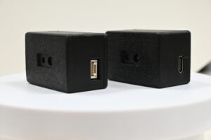
HM-LD1-NV supports UART, UDP, and UVC. UART may suit embedded designs that need straightforward serial communication and moderate data rates. UDP works well with networked companion computers, but the host software has to manage packet loss, ordering, buffering, and timestamps. UVC may simplify access through compatible video-class workflows. Verify which interface exposes depth maps, point clouds, confidence values, timestamps, configuration commands, and diagnostics.
SDK and Development Platform Support
The supplied information describes SDK support for Windows on x86, Linux on x86, Linux on ARM, Raspberry Pi, NVIDIA Jetson, ROS, and ROS 2 development. That sounds broad, but compatibility should still be checked against the exact processor, OS release, kernel, middleware distribution, connector, and production interface.
Typical Flight Integration Architecture
A common setup connects HM-LD1-NV to a companion computer through UART, UDP, or UVC. A vendor driver or SDK exposes depth data. Application software filters it, transforms coordinates, builds an obstacle map, and runs local planning. The companion computer then communicates with the autopilot through MAVLink or a native interface. A direct flight-controller connection may work in some designs, but only if protocol support, bandwidth, firmware, and processing capacity are adequate.
For broader positioning context, ComNav Technology provides information about GNSS and positioning systems. GNSS and lidar serve different but complementary roles: GNSS supports broader position estimation, while lidar supplies local geometric perception. This reference does not imply verified interoperability or a commercial partnership with the products discussed here.
Data Quality and Failure Handling
The software design should explicitly address invalid depth values, confidence thresholds, outlier rejection, temporal filtering, ground removal, cluster size, stale-frame timeouts, communication failure, sensor-health monitoring, coordinate conventions, data logging, and replay. A defined degraded or safe state is essential when measurements become unavailable or unreliable.
Mounting, Synchronization, and Calibration
Mounting Orientation
Mount the sensor where the airframe does not block its view. The angle should match the mission. A level forward view prioritizes walls, trees, and machinery. A downward tilt may reveal terrain sooner but sacrifices horizon coverage. Include normal aircraft pitch during acceleration and braking when choosing the final angle.
Vibration and Structural Stability
Solid-state sensing eliminates a rotating scanner, but the sensor coordinate frame still moves with the aircraft. A flexible bracket can change extrinsic calibration and create apparent point motion. Test the installed assembly across representative motor speeds, propeller conditions, payload configurations, and structural resonances.
Intrinsic and Extrinsic Calibration
Intrinsic calibration defines the relationship between depth pixels and sensor rays. Extrinsic calibration defines the rigid transformation between the lidar and the UAV body, IMU, camera, or navigation frame. Small angular errors create larger positional offsets at longer distances. Record calibration values for each assembly and verify them after maintenance, hard landings, or mechanical impact.
Timestamp Synchronization
Motion compensation depends on knowing when each depth frame was actually acquired. Host receipt time may not be acquisition time. Ask the supplier about timestamp behavior, clock source, buffering, transport delay, and synchronization options. Then test the whole stack for timing offsets under realistic processor and network loads.
HM-LD1-NV and HM-LD1 Product Specifications
HM-LD1-NV Compact 3D dToF Lidar

HM-LD1-NV is an all-in-one solid-state direct time-of-flight module intended for real-time depth perception in drones, robots, agricultural machines, and autonomous platforms. Its 940 nm VCSEL illumination and SPAD-based receiver support depth-map and point-cloud output. Published outdoor performance extends from 0.2 to 8 m at 80 klux, while indoor performance is listed from 0.5 to 25 m.
The 40 × 30 depth grid, 10 fps frame rate, 60° × 45° FOV, 28 g listed weight, and 1.2 W power consumption make the module relevant to compact UAV designs that require directional short- to medium-range sensing. UART, UDP, and UVC provide integration options for embedded controllers and companion computers. The product information also describes Raspberry Pi, NVIDIA Jetson, Linux, ARM, ROS, and ROS 2 development support.
Potential functions include drone obstacle detection, collision-avoidance input, robot navigation, terrain awareness, depth-based presence sensing, and privacy-preserving human perception without relying on RGB imagery. Class 1 eye safety is stated in the supplied product description; applicable compliance documentation should be requested for the production configuration.
| Resolution | 40 × 30 |
|---|---|
| Indoor ranging | 0.5–25 m |
| Outdoor ranging | 0.2–8 m at 80 klux |
| Ranging accuracy | ±3 cm |
| Field of view | 60° horizontal × 45° vertical |
| Weight | 28 g |
| Dimensions | 43.5 × 26.5 × 30 mm |
| Wavelength | 940 nm VCSEL |
| Frame rate | 10 fps |
| Interfaces | UART / UDP / UVC |
| Operating temperature | −20°C to 60°C |
| Power consumption | 1.2 W |
| Output | Depth map and point cloud |
HM-LD1 Solid-State dToF Lidar
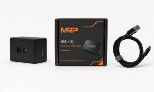
HM-LD1 is described as a solid-state SPAD dToF module that produces real-time depth images and 3D point-cloud data. Its listed use cases include UAV altitude support, terrain following, robot navigation, obstacle avoidance, SLAM development, distance detection, autofocus, presence sensing, object recognition, volume measurement, and zone monitoring.
Like HM-LD1-NV, the HM-LD1 listing states 40 × 30 resolution, 10 fps, ±3 cm accuracy, 60° × 45° FOV, UART/UDP/UVC interfaces, a −20°C to 60°C operating range, and 1.2 W power consumption. The HM-LD1 page lists a weight of 8 g and dimensions of 43.5 × 30 × 26.5 mm. These values should be confirmed against the exact orderable configuration.
| Dimensions | 43.5 × 30 × 26.5 mm |
|---|---|
| Indoor ranging | 0.5–25 m in the specification table |
| Outdoor ranging | 0.2–8 m; supporting copy references outdoor daytime operation |
| Ranging accuracy | ±3 cm |
| Field of view | 60° horizontal × 45° vertical |
| Weight | 8 g as listed on the HM-LD1 page |
| Resolution | 40 × 30 |
| Frame rate | 10 fps |
| Interfaces | UART / UDP / UVC |
| Operating temperature | −20°C to 60°C |
| Power consumption | 1.2 W |
| Output | Depth image and 3D point cloud |
| Specification | HM-LD1-NV | HM-LD1 | UAV selection relevance |
|---|---|---|---|
| Technology | Solid-state 3D dToF | Solid-state SPAD dToF | Provides direct depth data without mechanical scanning. |
| Resolution | 40 × 30 | 40 × 30 | Determines scene sampling and influences small-object detection. |
| Indoor range | 0.5–25 m | 0.5–25 m | Relevant to indoor inspection and GPS-denied flight. |
| Outdoor range | 0.2–8 m at 80 klux | 0.2–8 m | Must be validated for sunlight, surface, angle, and weather. |
| Accuracy | ±3 cm | ±3 cm | Supports clearance and obstacle-distance estimation. |
| FOV | 60° × 45° | 60° × 45° | Defines directional coverage and sensor-array layout. |
| Frame rate | 10 fps | 10 fps | Must be included in reaction-distance calculations. |
| Weight | 28 g | 8 g as listed | Confirm exact housing, cable, and production configuration. |
| Power | 1.2 W | 1.2 W | Include conversion losses and startup behavior. |
| Interfaces | UART / UDP / UVC | UART / UDP / UVC | Supports embedded and companion-computer integration. |
The 8 g and 28 g values appear on separate listings and should not be treated as interchangeable. Before design release, request the exact orderable part number, current datasheet revision, mechanical and connector drawings, supplied-unit mass, interface documentation, eye-safety information, SDK package, supported software versions, and outdoor sample data. For another product-focused perspective, read the HM-LD1 solid-state lidar guide for drone applications.
Application-Fit Recommendations
Indoor Inspection Drones
The published indoor range up to 25 m may fit warehouses, industrial buildings, tunnels, and infrastructure inspection work. Lidar can complement camera systems where lighting is poor, but dark surfaces, dust, repetitive structures, oblique walls, and narrow obstacles still need to be tested. An indoor maximum range should be treated as a boundary condition, not as a guaranteed detection distance.
Outdoor and Agricultural UAVs
The specified 8 m outdoor range at 80 klux makes HM-LD1-NV relevant to controlled short-range outdoor perception studies. Agricultural sites bring foliage, fine branches, dust, rapidly changing sunlight, vibration, and variable target angles. Cleaning procedures and optical-window protection need to be part of the operating plan, not an afterthought.
Terrain Following and Altitude Support
A downward-facing depth sensor can provide a local geometric profile, but crop canopy is not the same thing as bare ground. Navigation software has to define whether the aircraft follows the crop tops, the nearest return, or an estimated ground surface. The module should not be marketed or treated as a universal replacement for every altimeter or positioning source.
Reuse Across UAV and Ground-Robot Programs
UART, UDP, UVC, and Linux/ARM support may allow teams to reuse drivers and perception software across aerial and ground platforms. Shared middleware, logging, point-cloud filtering, and ROS components can reduce duplicated engineering work. Browse additional robotics and UAV application cases for broader deployment context.
Bench, Ground, and Flight Validation Plan
Phase 1: Bench Testing
Start with basic discipline. Verify output on every proposed interface, startup behavior, reconnection, measured power, frame rate, timestamp stability, packet loss, thermal behavior, minimum range, FOV limits, static accuracy, repeatability, and invalid-point behavior. Use traceable distance references and save raw data instead of relying on a visualization screen.
- ⚙️ Record the sensor serial number, firmware version, host configuration, and test date.
- ⚙️ Measure actual frame intervals and look for jitter, pauses, and stale timestamps.
- ⚙️ Cycle power repeatedly and verify predictable startup and recovery behavior.
- ⚙️ Test communication loss and reconnection before the unit is installed on an aircraft.
Phase 2: Target and Lighting Matrix
Build a controlled matrix using targets with different sizes, colors, materials, reflectivity levels, and incidence angles. Repeat the tests under indoor lighting, overcast skies, and representative direct sunlight. Record detection probability, median error, error distribution, valid-point percentage, first reliable detection distance, and false-return behavior.
Move each target across the center, corners, and edges of the FOV. For thin targets, include positions between nominal sample directions. If a wire is mission-critical, one successful detection at the center of the image proves very little.
Phase 3: Mounted Ground Testing
Install the lidar on the powered airframe and run the motors where it is safe to do so. Evaluate vibration, electrical noise, propeller and arm occlusion, enclosure reflections, thermal rise, network congestion, calibration stability, and time synchronization. A cart or controlled movement fixture can approach representative obstacles before the project moves to free flight.
Phase 4: Tethered or Protected Flight
Begin at low speed with large, diffuse obstacles. Use a safety pilot, protected test area, and independent stop mechanism. Compare logged detections, vehicle position, planner decisions, autopilot commands, and actual clearance. Confirm that stale, missing, or invalid data produces the intended safe response.
Phase 5: Flight-Envelope Expansion
Increase speed, lighting intensity, approach angle, clutter, pitch, roll, wind, mission duration, and obstacle complexity in controlled steps. Include negative tests such as connection loss, stale frames, obscured optics, sensor reboot, packet loss, and weak returns. Useful acceptance metrics include detection probability by target category, detection-distance percentiles, false-positive rate, invalid-depth percentage, end-to-end latency, frame loss, obstacle-clearance error, safe-stop success rate, thermal stability, and recovery after interruption.
Industrial Procurement and Supplier Checklist
Documents to Request
- ✅ Current datasheet and revision history
- ✅ Mechanical, connector, and cable drawings
- ✅ Interface-control document and pinout
- ✅ Eye-safety documentation
- ✅ Environmental, vibration, and reliability information where available
- ✅ SDK, API, firmware, and software-license documentation
- ✅ Supported operating-system and middleware versions
- ✅ Product-change notification and end-of-life policy
- ✅ Country of origin, lead time, lifecycle status, and production capacity
Sample and Production Evaluation
Confirm whether engineering samples use the same optical, mechanical, electrical, and firmware configuration planned for production. If unit-to-unit variation matters, test several samples instead of approving a design from one device. Record serial numbers, firmware revisions, calibration files, and configuration settings with every data set.
Software and Firmware Lifecycle
Ask about firmware upgrades, rollback, API stability, known limitations, bug reporting, access to raw and filtered data, configuration persistence, production programming, and long-term SDK maintenance. A sensor can look excellent on paper and still create industrial risk if its integration software changes without notice or is no longer supported.
Supply Continuity and Technical Support
For an industrial UAV, the lowest sample price is not always the lowest-risk decision. Evaluate manufacturing continuity, batch traceability, response time, customization requirements, minimum order quantities, lifecycle commitments, integration support, and product-change notification. Procurement should be involved early enough to ask these questions before the mechanical design is frozen.
How to Choose the Right Lidar Drone Sensor
Here’s the deal: selecting a lidar drone sensor takes more than comparing maximum distance. Start with aircraft speed, stopping behavior, target categories, directional coverage, lighting, compute platform, payload limits, and environmental exposure. Then compare minimum and maximum range, outdoor performance under a stated illumination level, FOV, depth resolution, frame rate, accuracy, interfaces, operating temperature, installed mass, power, software support, and supplier documentation.
HM-LD1-NV offers a compact specification set for short- to medium-range 3D UAV perception: 40 × 30 depth resolution, 10 fps output, ±3 cm ranging accuracy, a 60° × 45° FOV, 28 g listed weight, 1.2 W power consumption, and UART, UDP, and UVC interfaces. Its published outdoor performance is 0.2 to 8 m at 80 klux, while indoor range is listed as 0.5 to 25 m.
The final selection should come after bench testing, target testing, installed-airframe evaluation, and controlled flight trials. Set operating speed and avoidance margins from validated performance on the smallest, darkest, and most difficult required targets—not from the best-case maximum range.
Request Your Trial Sample (Exclusive Discount Code Included)
Are you developing the next generation of autonomous mobile robots (AMRs), delivery drones,or smart automation systems? Whether you are a fast-growing startup, an established engineering firm, or leading a specialized robotics project, finding high-precision sensors that fit your budget shouldn’t be your biggest hurdle.
At MyRobotProject.com, we believe exceptional perception technology should be accessible to projects of every size. To help you accelerate your prototype development and field testing,we are opening an exclusive discount program for first-time sample orders of our dTOF Solid-State Lidar Sensors.
Why Choose Our dTOF Solid-State Lidar?
Direct Time-of-Flight (dTOF) solid-state technology offers the reliability, speed, and precision needed for high-performance spatial awareness without the mechanical wear-and-tear of traditional rotating Lidar sensors.
Decent Quality Under Budget: Premium-grade performance engineered to respect your Bill of Materials (BOM) constraints.
Solid-State Reliability: Built for long service life, shock resistance, and demanding operational environments.
Versatile Applications: Ideal for obstacle avoidance, precision hovering, mapping, and micro-navigation in robotics and drone platforms.
Claim Your First-Trial Sample Order Discount
We want to empower your development cycle right from day one. If you are ordering your very first trial sample, we are offering an exclusive online introductory discount tailored to your project scope.
How to Apply:
Send an Email to [email protected]
Include the Following Details:
Your Company / Firm Name (or Project Name)
Your Estimated Project Quantity / Target Volume
Mention that this is your very first trial order
Include Promo Code: MRP-202607 in your subject line or email body.
Fast-Track Guarantee: Our technical sales team will review your project details and respond with your customized discount quote in less than 24 hours.
Ready to Build?
Don’t let budget constraints slow down your technical validation. Reach out today with code MRP-202607 and let’s bring your robot or drone project to life!
View HM-LD1-NV Specifications & Request Support ➔
Download the HM-LD1-NV Product Brochure
a short-flex design and a long-flex design for different robotics and UAV d…
Frequently Asked Questions About Lidar Drone Sensors
Will this lidar drone sensor work reliably in direct sunlight?
Is the sensor light and efficient enough for a small UAV?
How difficult is integration with a drone or companion computer?
Is a 25 m indoor range enough for drone obstacle avoidance?
Is 40 × 30 resolution sufficient for branches, wires, and small obstacles?
Can HM-LD1-NV connect directly to a flight controller?
How many lidar sensors does a drone need?
Can this lidar be used in rain, fog, or dusty agricultural environments?
Can a 3D lidar replace cameras on an autonomous drone?
What does Class 1 eye safety mean for UAV integration?
📚 References & Further Reading
- Industry Standard: onsemi semiconductor and sensing technology resources
- Industry Standard: ComNav Technology GNSS and positioning resources
- Related Guide: Compact dToF lidar for UAV obstacle avoidance
- Related Guide: HM-LD1 solid-state lidar for drone applications
- Product Documentation: DTOF SSL HM-LD1-NV Product Brochure
- Product Documentation: DTOF SSL HM-LD1 Product Brochure