

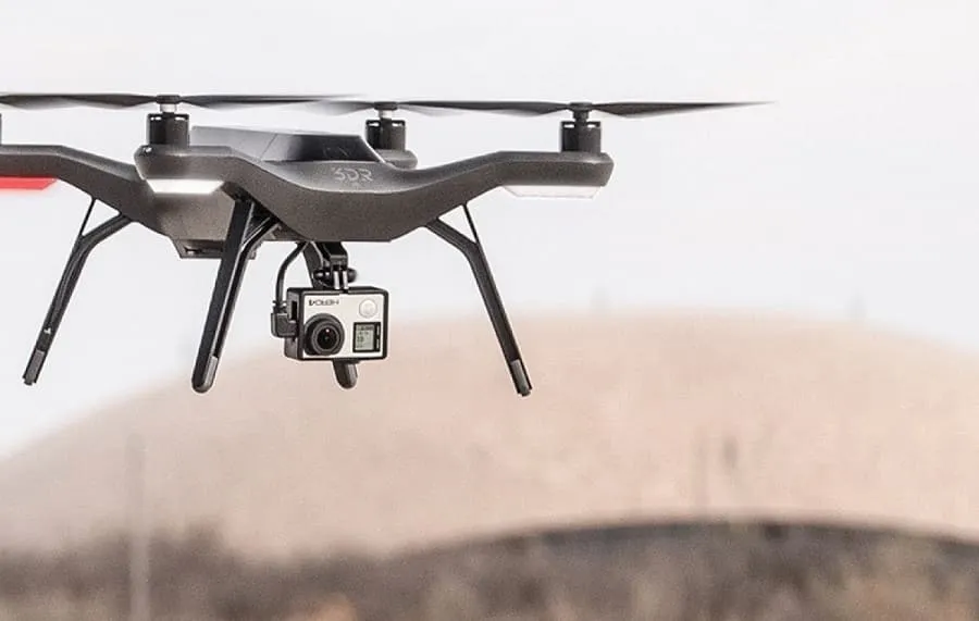
UAV LiDAR Sensor Selection Guide: Choose the Right Payload for Mapping or Obstacle Avoidance
Here’s the deal: a UAV LiDAR sensor that works perfectly inside a warehouse may struggle to detect a dark obstacle in direct sunlight. On the other hand, a high-end airborne survey payload may add more weight, cost, power draw, and processing overhead than a drone needs for altitude hold or short-range collision awareness. Maximum range by itself does not tell you whether a sensor will work. Field of view, frame rate, ranging accuracy, target reflectivity, ambient-light resistance, point density, payload weight, interfaces, timing, and georeferencing all matter.
This guide explains how to choose a UAV LiDAR sensor for two very different jobs: georeferenced 3D mapping and real-time perception. It covers LiDAR architectures, point-cloud requirements, GNSS and IMU integration, outdoor performance, airframe limits, software compatibility, and practical validation. It also looks at the lightweight HM-LD1 solid-state dToF module as an example for obstacle detection, altitude hold, terrain following, short-range inspection, and embedded UAV development—without pretending that a compact ranging module is automatically a complete survey-grade mapping payload.
Table of Contents
- 👉 Quick UAV LiDAR Selection Framework
- 👉 Mapping vs Obstacle Avoidance
- 👉 UAV LiDAR Sensor Types
- 👉 Specifications That Matter
- 👉 Survey Georeferencing and Accuracy
- 👉 Aircraft and Payload Integration
- 👉 Outdoor and Environmental Performance
- 👉 HM-LD1 Solid-State dToF LiDAR
- 👉 UAV LiDAR Selection Matrix
- 👉 Testing and Validation
- 👉 Common Selection Mistakes
- 👉 Procurement Checklist
- 👉 Frequently Asked Questions
- 👉 Recommended Next Steps
Quick answer: Use a synchronized LiDAR–GNSS–IMU payload when the required deliverable is a georeferenced survey point cloud. Use a compact, low-power dToF or solid-state LiDAR when the job is obstacle detection, terrain awareness, short-range inspection, altitude control, or local navigation.
Quick UAV LiDAR Selection Framework
The fastest way to narrow the market is to define the output before comparing specifications. “LiDAR data” is not one universal deliverable. A depth image sent to an autopilot is fundamentally different from a globally referenced LAS or LAZ point cloud prepared for engineering, forestry, construction, or topographic work.
a short-flex design and a long-flex design for different robotics and UAV d…
Step 1: Define the Required Output
Write down exactly what the aircraft must produce. That may be a georeferenced survey point cloud, a relative local point cloud, a multi-zone depth map, an obstacle alert, a single altitude measurement, terrain-following input, SLAM data, or the distance to a selected target. In the shop, this is where good projects separate from expensive experiments. The output determines whether you need a ranging module or a complete payload containing calibrated LiDAR, navigation sensors, synchronization hardware, storage, and processing software.
Step 2: Classify the UAV Mission
- ⚙️ Surveying and topographic mapping: Requires reliable georeferencing, adequate point density, trajectory processing, and independently verified map accuracy.
- ⚙️ Infrastructure or asset inspection: May require relative depth, controlled standoff distance, surface coverage, or globally positioned points, depending on the final deliverable.
- ⚙️ Obstacle avoidance and navigation: Prioritizes detection probability, low latency, useful field of view, low mass, and onboard processing compatibility.
- ⚙️ Altitude hold and terrain following: Requires stable downward or forward ranging over representative ground materials, slopes, vegetation, and lighting conditions.
Step 3: Set Measurable Performance Thresholds
Define the minimum outdoor detection distance, measurement accuracy, flight altitude, maximum ground speed, smallest object to detect, horizontal and vertical coverage, payload-mass limit, electrical power, update rate, acceptable latency, interface, software platform, and operating-temperature range. For avoidance, calculate the distance traveled during the entire sensing and control cycle. For mapping, define horizontal and vertical accuracy, ground-point density, coverage rate, and output format.
Selection principle: Start with the mission output and environmental limits. Do not start with an advertised maximum-range number.
Mapping and Obstacle Avoidance Are Different LiDAR Missions
Look, a survey payload and an obstacle-avoidance sensor may both use laser ranging, but that does not make them interchangeable. Their engineering requirements are different. Treating them as the same can lead to inaccurate maps, inadequate reaction distance, excessive payload mass, or a data path that cannot operate in real time.
Requirements for Survey and Geospatial Mapping
Airborne survey mapping requires calibrated scanner geometry, accurate timestamps, GNSS positioning, an IMU, measured lever-arm offsets, boresight calibration, flight-trajectory processing, suitable point density, enough swath coverage, and repeatable absolute and relative accuracy. RTK or PPK corrections may improve the aircraft trajectory, but they do not eliminate the need for timing, attitude estimation, mounting calibration, and independent checkpoints.
Raw range accuracy is only one line in the survey error budget. A timing offset moves a point along the flight path. An IMU attitude error displaces it across the ground. A bad lever-arm measurement shifts the relationship among the GNSS antenna, IMU, and LiDAR origin. Boresight misalignment can produce visible differences between overlapping flight strips. These errors generally become more important as flight altitude and target distance increase.
Requirements for Obstacle Avoidance and Navigation
Real-time perception puts the emphasis somewhere else: low latency, reliable outdoor range, practical horizontal and vertical coverage, low mass, modest power consumption, and dependable communication with the flight controller or companion computer. The sensor must identify an obstacle soon enough for the aircraft to brake, climb, descend, turn, or stop with a defined margin.
A compact depth sensor can be useful for local navigation without producing a survey-grade map. The reverse is also true. A survey scanner may collect excellent point clouds and still be unsuitable for collision avoidance if its processing workflow or data latency cannot support an immediate control decision.
| Requirement | Survey Mapping | Obstacle Avoidance |
|---|---|---|
| Primary output | Georeferenced 3D point cloud | Relative depth or obstacle information |
| Positioning | GNSS/RTK or PPK plus IMU | Local coordinates may be sufficient |
| Calibration | Timing, scanner, lever arm, and boresight | Sensor-to-airframe extrinsic calibration |
| Range priority | Must support flight altitude and target geometry | Must exceed reaction and maneuvering distance |
| Coverage priority | Swath width and point density | Directional field of view and blind zones |
| Processing | Trajectory and point-cloud processing | Low-latency onboard interpretation |
| Validation | Checkpoints, cross strips, and repeat surveys | Detection probability and reaction-time tests |
UAV LiDAR Sensor Types and How They Work
LiDAR measures distance by emitting light and analyzing the returned signal. The architecture affects range, angular coverage, spatial detail, mechanical complexity, size, power, latency, and cost. For a broader introduction, review this guide explaining what LiDAR technology is and how it works.
Direct Time-of-Flight LiDAR
Direct time-of-flight, or dToF, LiDAR emits a light pulse and measures how long reflected photons take to return. Since the speed of light is known, the electronics can convert that round-trip time into distance. Real performance depends on emitted optical energy, receiver sensitivity, detector design, target reflectivity, incidence angle, background light, optical filtering, and signal-processing algorithms.
SPAD-based receivers can detect very low light levels and are commonly used in compact time-of-flight systems. Multi-zone dToF modules produce a depth image in which each zone represents part of the scene. That output can support object presence, altitude measurement, near-field perception, landing assistance, and local navigation.
Solid-State LiDAR
Solid-state LiDAR reduces or eliminates large mechanical scanning components. The usual benefits are compact packaging, low mass, simpler embedded integration, and less mechanical complexity. But “solid state” is not a performance specification. You still need to compare field of view, depth resolution, outdoor range, frame rate, target detectability, latency, and environmental behavior. For more context on optical emitters, detectors, and semiconductor sensing, see ams OSRAM.
Mechanical Scanning LiDAR
Mechanical systems use rotating or oscillating hardware to sweep laser measurements across a scene. They can provide broad angular coverage and established point-cloud workflows, which is why they are common in mobile robotics and airborne scanning. The tradeoffs include mass, vibration, mounting stiffness, power, shock sensitivity, scan geometry, and moving-component lifecycle.
Flash and Multi-Zone Depth Sensing
Flash-style and multi-zone sensors illuminate a scene and measure depth across a receiver array or defined group of zones. They can produce a full depth frame without rotating the sensor. These compact outputs are useful for presence sensing, landing assistance, obstacle-related algorithms, altitude control, and near-field robotic vision. A low-resolution depth frame, however, should not be confused with the dense and georeferenced sampling expected from an airborne survey scanner.
FMCW and Emerging Architectures
Frequency-modulated continuous-wave LiDAR analyzes frequency changes in the returned optical signal and may support range and relative-velocity estimation at the same time. As with every architecture, buy based on demonstrated system performance, interfaces, calibration, environmental data, production maturity, and integration support—not a technology label. SOS LAB provides additional market context for solid-state and scanning LiDAR development.
UAV LiDAR Specifications That Matter
Range and Detection Probability
Maximum range means very little unless the test conditions are stated. Ask whether the measurement was made indoors or outdoors, under what solar illumination, against what target size and reflectivity, at which incidence angle, and with what confidence requirement. A large white wall can return far more optical energy than a dark cable, narrow branch, wet surface, or target viewed at an oblique angle.
For obstacle avoidance, use a minimum reliable detection distance rather than a best-case maximum. That distance must cover acquisition, communication, processing, command generation, aircraft response, maneuvering, and a safety margin. For survey mapping, the range must support flight altitude, terrain variation, swath geometry, atmospheric conditions, and required point quality.
Accuracy, Precision, and Resolution
Accuracy is how close a reported distance is to the true value. Precision is repeatability from one measurement to the next. Range resolution concerns the ability to distinguish separate distances. Angular resolution describes the spacing between measurement directions. Depth-image resolution is the number of depth zones or pixels in a frame.
Do not use those terms interchangeably. A ±3 cm ranging specification does not mean the final UAV map will be accurate to ±3 cm. Map accuracy also depends on navigation, timestamps, mounting, trajectory processing, calibration, altitude, and target geometry.
Field of View and Sensor Placement
Horizontal and vertical field of view determine directional coverage. A forward-facing sensor can watch the direction of travel, while a downward-facing sensor may support altitude control or terrain following. Neither setup automatically covers the sides, rear, or upper airspace. Landing gear, payloads, propellers, and the airframe can also block part of the optical path. Full coverage may require multiple sensors or fusion with cameras, radar, or other technologies.
Frame Rate, Latency, and Aircraft Speed
At 10 m/s, an aircraft travels 1 m between frames when the sensor runs at 10 fps. That simple calculation does not include transmission, filtering, object detection, command processing, actuator response, or aircraft dynamics. The only number that matters operationally is the complete end-to-end reaction time measured on the actual aircraft.
Point Density and Spatial Detail
Mapping point density depends on pulse or measurement rate, scan pattern, altitude, speed, swath width, overlap, surface geometry, and filtering. A 40 × 30 output contains 1,200 zones per frame, but that does not make it a dense airborne survey. Tie spatial detail to the smallest feature or obstacle that must be detected rather than a headline data-sheet number.
Weight, Dimensions, and Center of Gravity
Payload mass affects endurance, propulsion margin, acceleration, and regulatory takeoff weight. Physical size affects mounting position, airflow, airframe clearance, and cable routing. Engineers also need to check center of gravity, structural stiffness, vibration, optical-window placement, and whether a fixed or gimballed installation makes sense.
Power Consumption and Thermal Management
Compare nominal power, supply voltage, peak current, regulator capacity, and start-up behavior. Low nominal consumption helps, but the complete installation must prevent voltage dips, electrical noise, and overheating. In the real world, an enclosed sensor sitting in direct sun may run much hotter than the surrounding air.
Interfaces, SDKs, and Data Formats
UART, UDP, UVC, USB, Ethernet, and CAN describe communication paths, not application compatibility. Confirm the message format, timestamp method, coordinate conventions, bandwidth, invalid-value handling, packet-loss behavior, SDK architecture, firmware process, logging tools, and driver availability. If ROS or ROS 2 is required, verify the exact distribution and maintenance status.
Survey Georeferencing, Timing, and Accuracy
Why a LiDAR Sensor Alone Is Not a Survey System
A LiDAR module measures points relative to its own optical origin and coordinate frame. To place those points in a global engineering or geographic coordinate system, the system needs the aircraft’s position and orientation at the exact measurement time. That normally requires LiDAR, GNSS, and IMU data in one calibrated and synchronized workflow.
GNSS, RTK, and PPK Positioning
Standalone GNSS may be fine for general navigation but often cannot support demanding survey accuracy. RTK applies corrections during operation, while PPK applies them during post-processing. Both require suitable observations, correction data, antenna placement, and trajectory processing. GNSS-denied or obstructed environments create additional localization problems that may require SLAM, control points, or another positioning method.
IMU Quality and Attitude Error
The IMU estimates roll, pitch, and heading. Even a small angular error can move a LiDAR point across the ground, and the displacement grows with target distance. An attitude error that looks harmless at 3 m may be unacceptable when the UAV is 50 m above the surface. Heading quality is especially important for strip alignment and linear features.
Timestamp Synchronization
Software receipt time is usually inadequate for rigorous georeferencing because it contains variable communication and operating-system delay. Survey systems may use pulse-per-second signals, hardware triggers, disciplined clocks, or precise device timestamps. Clock offset and drift need to be characterized through the mission, not just at start-up.
Lever-Arm and Boresight Calibration
The lever arm is the measured spatial offset among the LiDAR origin, IMU reference point, and GNSS antenna. Boresight calibration determines angular alignment. Incorrect values can create strip mismatch, duplicated edges, sloped surfaces, and location bias. Recheck calibration after mechanical changes, hard landings, or significant impacts.
Verifying Survey Accuracy
Verify mapping performance with independent checkpoints, known surfaces, overlapping strips, cross-flight lines, and repeated missions. Report horizontal and vertical errors separately. Be clear about whether a claim refers to relative precision, absolute accuracy, or raw range performance. RMSE values should include the number and distribution of checkpoints, coordinate reference system, and processing method.
Aircraft, Electrical, and Software Integration
Flight Controller or Companion Computer?
A low-bandwidth altitude or distance reading may be handled directly by a compatible flight controller. Depth frames and point clouds usually need a Raspberry Pi, NVIDIA Jetson, industrial computer, or custom embedded processor. The companion computer can filter measurements, detect obstacles, transform coordinate frames, and send simplified commands or distance messages to the autopilot.
Mechanical Mounting and Vibration
The mount must hold a repeatable orientation while protecting the sensor from excessive vibration and shock. It also has to keep the optical path clear of the airframe and contamination. Any protective window should be tested for transmission loss, internal reflections, condensation, scratching, and sunlight behavior. Weather protection cannot be assumed unless the complete enclosure has been validated.
Coordinate Frames and Extrinsic Calibration
Integration software may use a sensor frame, aircraft body frame, navigation frame, and world frame. Confirm axis directions, handedness, rotation order, and units. A depth image that is inverted or rotated incorrectly can cause unsafe control behavior even when every range value is technically correct.
Data Bandwidth and Logging
Test UDP throughput, serial baud rate, USB or UVC behavior, storage write speed, processor loading, and packet loss under realistic onboard conditions. Logging should preserve timestamps and invalid measurements so failures can be diagnosed after flight. A data path that works on a desktop may behave very differently when the onboard computer is also running navigation, video, communications, and control software.
Development Platform Support
The HM-LD1 is stated to support SDK development on x86 Windows, x86 Linux, and ARM Linux. Before procurement, verify exact operating-system versions, processor architecture, compiler requirements, sample applications, API documentation, firmware compatibility, ROS support if needed, and long-term driver maintenance.
Outdoor and Environmental Performance
Sunlight and Ambient Optical Noise
Solar radiation introduces background photons that can reduce usable range or increase invalid measurements. Never apply an indoor range number directly to daytime flight planning. Test in shade, direct sun, low-angle sun, backlit conditions, and changing illumination. Record detection probability and invalid-depth rate—not just the longest return observed.
Target Reflectivity and Incidence Angle
Dark matte materials generally return less light than bright diffuse targets. Glass, water, polished metal, retroreflective signs, vegetation, and sloped surfaces may produce complex or inconsistent behavior. Detecting a wall does not prove that the sensor can detect a wire, thin branch, or narrow pole at the same range.
Rain, Fog, Dust, and Airborne Particles
Water droplets, fog, dust, and other particles can scatter emitted light, shorten range, create false returns, or dirty the optical surface. Application-specific testing is necessary. Do not assume a sensor is rainproof, dustproof, or suitable for all-weather autonomy without verified enclosure and system-level ratings.
Temperature and Enclosure Design
The HM-LD1 has a stated operating-temperature range of −20°C to 60°C. The finished installation must still account for solar heating, airflow, processor heat, regulator heat, enclosure color, condensation, altitude, and cable performance. Sensor temperature can differ substantially from ambient temperature.
HM-LD1 Solid-State dToF UAV LiDAR Sensor
The HM-LD1 solid-state dToF LiDAR is a compact multi-zone depth module intended for real-time distance measurement and environmental perception. It uses SPAD dToF technology and provides depth images and 3D point-cloud data for embedded development. Its low stated mass and power consumption make it relevant to UAV projects where endurance, payload capacity, and installation space are tight.
The module is specified for indoor ranging from 0.5 to 25 m and outdoor ranging from 0.2 to 8 m. The supplied description states that outdoor measurements can reach 8 m on a clear summer day at an assumed illuminance of 80,000 lux. That figure needs to be checked against actual target materials, object sizes, incidence angles, sun position, aircraft motion, and required detection confidence.
With a 40 × 30 output, the HM-LD1 provides 1,200 depth zones per frame at a stated 10 fps. Its 60° horizontal by 45° vertical field of view supports directional depth perception. UART, UDP, and UVC interfaces allow connection to PCs, Raspberry Pi systems, embedded platforms, compatible control architectures, and development computers.
Potential uses include altitude hold, terrain following, obstacle-related development, short-range infrastructure inspection, local navigation, experimental SLAM, object recognition, volume measurement, autofocus assistance, presence detection, and zone monitoring. Distance measurements may also support inspection of bridges, expressway structures, dams, and other hard-to-approach assets, provided the aircraft and sensing system are validated for the job.
| Specification | HM-LD1 Value | UAV Selection Relevance |
|---|---|---|
| Sensing technology | SPAD-based direct time of flight, solid state | Supports real-time depth and relative 3D perception without a mechanical scanning assembly. |
| Dimensions | 43.5 mm × 30 mm × 26.5 mm | Compact form factor for small UAVs and embedded payload bays. |
| Weight | 28 g | Limits payload impact compared with larger integrated systems. |
| Indoor ranging capability | 0.5–25 m | Relevant to indoor navigation, warehouse inspection, and low-light operation. |
| Outdoor ranging capability | 0.2–8 m | Must be compared with speed, maneuvering distance, sunlight, and target reflectivity. |
| Ranging accuracy | ±3 cm | Stated distance accuracy; it is not complete georeferenced map accuracy. |
| Field of view | 60° horizontal × 45° vertical | Provides directional coverage; additional sensing may be required for other directions. |
| Specification | HM-LD1 Value | Integration Consideration |
|---|---|---|
| Depth resolution | 40 × 30 | Provides 1,200 depth zones per frame for perception algorithms. |
| Frame rate | 10 fps | Total reaction time must include transmission, processing, control, and aircraft response. |
| Interfaces | UART, UDP, UVC | Supports connection to embedded computers, PCs, and compatible control systems. |
| Operating temperature | −20°C to 60°C | The complete enclosure and thermal environment still require validation. |
| Power consumption | 1.2 W | Low stated demand benefits battery-powered UAV integration. |
| SDK platforms | x86 Windows, x86 Linux, ARM Linux | Supports development on common desktop and embedded architectures. |
| Output capability | Depth images and 3D point-cloud data | Relevant to local perception, visualization, navigation research, and distance analysis. |
Where the HM-LD1 Fits Best
- ✅ Forward- or downward-facing obstacle sensing
- ✅ Low-altitude terrain awareness and terrain following
- ✅ UAV altitude hold and relative height measurement
- ✅ Indoor navigation and robotic vision
- ✅ Short-range asset inspection and standoff measurement
- ✅ Experimental local SLAM and multi-sensor perception
- ✅ Object-presence, volume-measurement, and zone-monitoring systems
- ✅ Camera autofocus, object recognition, and user-presence development
What Buyers Must Validate
Before deployment, validate daylight range on representative targets, thin and dark obstacle detection, effective reaction distance, 10 fps suitability, interface latency, invalid-data handling, flight-controller communication, enclosure requirements, sensor alignment, and behavior near glass, water, vegetation, and reflective metal. Obstacle sensing by itself does not guarantee collision avoidance.
The supplier states that it specializes in perception and positioning modules for robots and UAVs, with independent research and development, product-integration support, in-house manufacturing, stable supply, customization, and OEM/ODM services. Procurement teams should discuss support scope, customization feasibility, lead time, lifecycle, firmware requirements, and volume-production expectations directly with the supplier.
Download the DTOF SSL HM-LD1 product brochure for additional product information.
View Product Details & Pricing ➔
UAV LiDAR Sensor Selection Matrix
| Mission | Preferred Characteristics | Positioning Requirement | Primary Validation Metric |
|---|---|---|---|
| Topographic survey | Long range, suitable point rate, calibrated scan geometry | RTK/PPK GNSS and appropriate IMU | Independent checkpoint RMSE |
| Forestry mapping | Canopy penetration, adequate swath, return information | GNSS/IMU trajectory | Ground classification and point density |
| Power-line mapping | High spatial detail and sufficient range | Precise georeferencing | Conductor detection and absolute position |
| Bridge or facade inspection | Directional coverage, compact mounting, useful standoff range | Relative or global, depending on deliverable | Surface coverage and standoff consistency |
| Forward obstacle avoidance | Low latency, outdoor range, relevant field of view | Local coordinates may be sufficient | Detection probability and reaction distance |
| Altitude hold | Stable downward ranging and predictable updates | Relative height | Height stability over representative terrain |
| Indoor navigation | Compact sensor, useful field of view, SLAM compatibility | GNSS normally unavailable | Localization drift and collision rate |
| Terrain following | Forward/downward coverage and predictable latency | Flight-controller integration | Terrain-clearance error |
- ⚙️ If the deliverable requires absolute coordinates, start with a georeferenced survey payload.
- ⚙️ If the output is a real-time depth, distance, or obstacle signal, start with compact perception sensors.
- ⚙️ Reject any sensor whose validated outdoor range is shorter than the required maneuvering distance.
- ⚙️ Check whether the field of view creates unacceptable blind zones.
- ⚙️ Confirm mass, power, interface, software, and processor compatibility.
- ⚙️ Validate the complete sensor-to-autopilot loop before operational deployment.
Testing and Validating a UAV LiDAR Sensor
Bench Test the Sensor First
In the shop, start with known distances and raw logs. Measure distance bias, repeatability, cold-start behavior, frame rate, packet loss, interface stability, power consumption, thermal behavior, invalid zones, and recovery after disconnection. Repeat the tests after the sensor reaches operating temperature.
Use Representative Targets
Include dark fabric, foliage, concrete, painted metal, reflective signs, poles, cables, glass, water, and sloped surfaces. Use target sizes that match actual obstacles. Testing only against a large white wall will usually produce an unrealistically favorable result.
Test Across Real Daylight Conditions
Run tests in shade, overcast weather, direct sun, low-angle sun, and backlighting. Measure detection probability, depth bias, noise, invalid-return rate, and stability over time. Repeat each test at multiple target angles and distances.
Progress from Ground Tests to Controlled Flights
- ⚙️ Static ground test with measured targets
- ⚙️ Hand-carried motion test
- ⚙️ Propellers-on vibration and interference test
- ⚙️ Tethered or protected hover test
- ⚙️ Low-speed controlled flight
- ⚙️ Representative operational-speed test
- ⚙️ Sensor-loss, invalid-data, and packet-drop test
Measure End-to-End Reaction Time
The minimum required detection distance equals the distance traveled during total system latency, plus maneuvering or stopping distance, plus an operational safety margin. Use measured aircraft response rather than assuming immediate deceleration. Run the test under worst-case processor load and realistic communication delays.
Validate Survey Workflows Independently
For mapping systems, use surveyed checkpoints, cross-flight lines, repeated missions, stable reference surfaces, and documented processing settings. Report horizontal and vertical performance separately. Review available robotics and sensing case studies for additional application context.
Common UAV LiDAR Selection Mistakes
- ⚙️ Buying by maximum range alone: Range changes with sunlight, reflectivity, object size, target angle, and confidence requirements.
- ⚙️ Treating range accuracy as map accuracy: Georeferenced results also depend on GNSS, IMU, timing, lever arms, boresight, and processing.
- ⚙️ Ignoring field-of-view blind zones: Forward coverage does not protect the sides, rear, upper airspace, or every descent direction.
- ⚙️ Evaluating frame rate without total latency: Transmission, filtering, command generation, and aircraft response all add delay.
- ⚙️ Assuming an interface guarantees compatibility: UART or UDP access does not prove timestamp, autopilot, ROS, or message-format support.
- ⚙️ Using indoor range for outdoor planning: Solar background can materially reduce usable range.
- ⚙️ Ignoring small-object detectability: A sensor may detect walls but miss wires, twigs, or narrow poles.
- ⚙️ Skipping payload calibration: Sensor position and orientation relative to the aircraft must be measured.
- ⚙️ Selecting survey hardware without a workflow: Good hardware still needs trajectory processing, quality control, and defined deliverables.
- ⚙️ Skipping fault handling: The UAV must respond safely to blocked optics, invalid measurements, dropped packets, and sensor restarts.
UAV LiDAR Procurement Checklist
Mission Requirements
- ✅ What exact output is required?
- ✅ Is the mission mapping, inspection, navigation, avoidance, altitude hold, or terrain following?
- ✅ What are the minimum altitude and maximum flight speed?
- ✅ What is the smallest object or feature that must be detected?
- ✅ Does the deliverable require absolute geographic coordinates?
Optical and Ranging Performance
- ✅ Is the stated range indoor or outdoor?
- ✅ At what illumination, target reflectivity, target size, and incidence angle was it measured?
- ✅ What are the accuracy, precision, and invalid-return rate?
- ✅ What are the horizontal and vertical fields of view?
- ✅ Can the sensor detect representative dark, thin, angled, or reflective targets?
UAV and Software Integration
- ✅ What are the verified dimensions, mass, mounting orientation, voltage, power, and peak current?
- ✅ Which communication interfaces and timestamp options are available?
- ✅ Does the optical field intersect the airframe or propellers?
- ✅ Does the SDK support the exact processor and operating-system version?
- ✅ Can raw measurements be logged and firmware updated?
- ✅ What happens during packet loss, invalid readings, or sensor restart?
Survey-Specific Checks
- ✅ Are GNSS and IMU integration included?
- ✅ Is hardware synchronization supported?
- ✅ Are lever-arm and boresight procedures documented?
- ✅ Can claimed accuracy be verified with independent checkpoints?
- ✅ Are appropriate point-cloud and survey output formats available?
Supplier Support
- ✅ Are mechanical drawings, SDK documentation, and example code available?
- ✅ Can the supplier provide integration assistance?
- ✅ Are firmware, interface, or enclosure customization options available?
- ✅ What are the lead time, lifecycle, stable-supply, and OEM/ODM conditions?
- ✅ Can an evaluation unit be tested before volume procurement?
HM-LD1 dToF Solid-State LiDAR: Compact Depth Sensing for UAVs & Robotics
Frequently Asked Questions About UAV LiDAR Sensors
How do I choose a UAV LiDAR sensor for surveying versus obstacle avoidance?
Can a lightweight LiDAR module deliver survey-grade mapping results?
What compatibility should beginners verify before buying a UAV LiDAR sensor?
How much outdoor range does a UAV obstacle-avoidance LiDAR need?
Is a wide field of view always better for a UAV LiDAR sensor?
What is the difference between LiDAR resolution and point density?
Can one LiDAR sensor provide complete UAV collision avoidance?
How does frame rate affect UAV obstacle detection?
Does ±3 cm ranging accuracy mean the final map will be accurate to ±3 cm?
What information should I send a supplier before requesting a recommendation?
Recommended Next Steps
A UAV LiDAR sensor should be selected as part of the complete airborne measurement and control system. Survey teams should prioritize calibrated scanning, synchronization, GNSS and IMU integration, point density, trajectory processing, and independently verified accuracy. Obstacle-avoidance and terrain-awareness developers should prioritize outdoor detection probability, field of view, total latency, update rate, mass, power, software support, and safe fault handling.
For compact real-time depth sensing, the HM-LD1 offers a stated 28 g solid-state design, 40 × 30 depth resolution, 10 fps output, a 60° × 45° field of view, UART/UDP/UVC interfaces, 1.2 W power consumption, and outdoor ranging up to 8 m under stated conditions. Those characteristics make it a candidate for short-range UAV perception, altitude control, terrain following, inspection, and obstacle-related development, subject to representative bench and flight testing.
Recommended actions:
Request Your Trial Sample (Exclusive Discount Code Included)
Are you developing the next generation of autonomous mobile robots (AMRs), delivery drones,or smart automation systems? Whether you are a fast-growing startup, an established engineering firm, or leading a specialized robotics project, finding high-precision sensors that fit your budget shouldn’t be your biggest hurdle.
At MyRobotProject.com, we believe exceptional perception technology should be accessible to projects of every size. To help you accelerate your prototype development and field testing,we are opening an exclusive discount program for first-time sample orders of our dTOF Solid-State Lidar Sensors.
Why Choose Our dTOF Solid-State Lidar?
Direct Time-of-Flight (dTOF) solid-state technology offers the reliability, speed, and precision needed for high-performance spatial awareness without the mechanical wear-and-tear of traditional rotating Lidar sensors.
Decent Quality Under Budget: Premium-grade performance engineered to respect your Bill of Materials (BOM) constraints.
Solid-State Reliability: Built for long service life, shock resistance, and demanding operational environments.
Versatile Applications: Ideal for obstacle avoidance, precision hovering, mapping, and micro-navigation in robotics and drone platforms.
Claim Your First-Trial Sample Order Discount
We want to empower your development cycle right from day one. If you are ordering your very first trial sample, we are offering an exclusive online introductory discount tailored to your project scope.
How to Apply:
Send an Email to [email protected]
Include the Following Details:
Your Company / Firm Name (or Project Name)
Your Estimated Project Quantity / Target Volume
Mention that this is your very first trial order
Include Promo Code: MRP-202607 in your subject line or email body.
Fast-Track Guarantee: Our technical sales team will review your project details and respond with your customized discount quote in less than 24 hours.
Ready to Build?
Don’t let budget constraints slow down your technical validation. Reach out today with code MRP-202607 and let’s bring your robot or drone project to life!
📚 References & Further Reading
- Industry Standard: ams OSRAM optical and semiconductor sensing resources
- Industry Standard: SOS LAB LiDAR technology resources
- Related Guide: What Is LiDAR Technology?
- Product Resource: HM-LD1 Solid-State dToF LiDAR
- Application Examples: Robotics and sensing case studies






