


3D LiDAR Sensor Buying Guide for Robots, Drones, and Industrial Automation
Here’s the deal: choosing a 3D LiDAR sensor is not as simple as buying the model with the longest advertised range. A sensor that works beautifully on an indoor autonomous mobile robot may produce far less usable depth data when it is mounted on a drone flying in bright sunlight. In the same way, a high-resolution scanner may add processing load, power draw, weight, heat, and integration work that a basic proximity-detection system simply does not need.
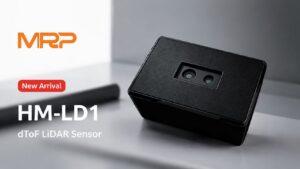
Look at the complete perception system. Range, field of view, spatial resolution, frame rate, target reflectivity, ambient light, interfaces, environmental protection, mounting, host processing, and software support all have to work together. This guide explains how to compare 3D LiDAR sensors for robots, drones, and industrial automation without getting distracted by headline specifications. It also examines the HM-LD1 solid-state dToF module as a practical example: a compact 28 g sensor with 40 × 30 depth resolution, a 60° × 45° field of view, 10 fps output, multiple interfaces, and separate indoor and outdoor ranging specifications.
Table of Contents
- 👉 What Is a 3D LiDAR Sensor?
- 👉 How 3D LiDAR Sensing Works
- 👉 Types of 3D LiDAR Technology
- 👉 Specifications That Matter When Buying
- 👉 Requirements by Application
- 👉 Outdoor and Environmental Performance
- 👉 Hardware, Data, and Software Integration
- 👉 HM-LD1 Solid-State 3D LiDAR Specifications
- 👉 Step-by-Step Sensor Selection Workflow
- 👉 Testing and Validation Before Deployment
- 👉 Supplier and Lifecycle Evaluation
- 👉 3D LiDAR Sensor Buying Checklist
- 👉 Final Recommendation
- 👉 Frequently Asked Questions
What Is a 3D LiDAR Sensor?
A 3D LiDAR sensor measures distance to many points in a scene by transmitting light and analyzing the returned signal. Those measurements can be delivered as a depth image or converted into a three-dimensional point cloud. That gives a robot, drone, camera, or automated machine usable information about object distance, position, shape, height, and open space.
A single-point rangefinder measures one optical path. A 2D LiDAR usually scans across one plane and is commonly used to build a horizontal map around a mobile robot. A 3D LiDAR captures depth in both horizontal and vertical directions. That extra vertical information is what lets a machine see tabletops, dock edges, overhanging structures, pallet openings, ramps, suspended loads, tree branches, and other hazards that may never cross a conventional horizontal scan plane.
One important point gets missed in a lot of purchasing discussions: “3D LiDAR” does not automatically mean a dense, camera-like point cloud. A compact 40 × 30 array and a large rotating scanner can both produce legitimate 3D measurements, but they are built for very different jobs. Point count, coverage, update rate, power, weight, price, and processing requirements can differ by an order of magnitude or more.
Depth Images Versus Point Clouds
A depth image stores a distance value at each sensing position. Since the data stays in an organized row-and-column format, it is convenient for image-style filtering, segmentation, region-of-interest processing, floor detection, and obstacle-zone logic. In the shop, that can be the quickest route when the controller only needs to answer a practical question such as, “Is anything inside this stopping zone?”
A point cloud converts depth values into X, Y, and Z coordinates using the sensor’s calibrated optical geometry. Point clouds are useful for spatial measurement, obstacle segmentation, mapping, localization, surface analysis, and sensor fusion. They also make it easier to transform several sensors into a shared robot coordinate frame.
Neither representation is universally better. Depth frames may use less processing when the application works with occupied image regions. Point clouds may be easier to use when data must be aligned with a robot base, manipulator, camera, IMU, or map. The right choice depends on the controller, software stack, calibration process, and machine objective.
Why 3D Perception Matters
Three-dimensional perception allows machines to detect low and elevated obstacles, estimate terrain slope, measure object height or volume, monitor restricted spaces, assist with docking, and maintain UAV altitude. It also provides absolute scale. A passive monocular camera cannot reliably determine absolute distance without motion, calibration, known object dimensions, or other assumptions.
That does not mean LiDAR replaces every other sensor. Cameras contribute color and texture. Radar can perform well in weather and measure motion. Ultrasonic sensors are inexpensive at short range. IMUs provide motion information. A well-designed machine often combines these technologies instead of forcing one sensor to do every job.
How 3D LiDAR Sensing Works
A LiDAR measurement starts when an emitter sends a controlled optical pulse or modulated signal into the scene. The light reaches a surface, and some of it reflects toward the receiver. The detector records that return, and the sensor uses timing or phase information to calculate distance. Calibration data assigns each measurement to a viewing direction so the module can build an organized depth frame or a set of 3D points.
With direct time of flight, normally abbreviated as dToF, distance is calculated from the speed of light multiplied by the round-trip travel time, divided by two. The division matters because the measured time includes the trip from the sensor to the target and the return trip back to the detector.
The equation is straightforward. Real hardware is not. The receiver must separate a weak useful reflection from sunlight, artificial lighting, detector noise, enclosure reflections, and returns from the wrong surface. Internal filtering and confidence logic may reject questionable measurements. That is why real depth frames often include invalid pixels, outliers, edge artifacts, or reduced range under difficult conditions.
Direct Time of Flight and SPAD Detection
A single-photon avalanche diode, or SPAD, is designed to detect extremely low levels of returned light with precise timing. In a solid-state array, multiple sensing elements collect depth measurements across a fixed field of view without an externally rotating scanner. This arrangement can support low weight, compact packaging, consistent optical coverage, and direct depth-frame output.
Look, “solid state” does not mean “immune to real-world problems.” Ambient light, target reflectivity, target size, incidence angle, temperature, multipath, integration settings, optical filtering, and signal-processing choices still affect measurement quality. A solid-state module may eliminate an exposed rotating mechanism, but it does not eliminate the need for application testing.
For a closer explanation of how individual range measurements become visual depth information, read dToF LiDAR imagery explained: depth maps.
Types of 3D LiDAR Technology
LiDAR architectures should not be compared on maximum range or price alone. Each design distributes optical energy, samples the environment, and packages its data differently. The right architecture depends on whether the machine needs panoramic mapping, detailed geometry, compact fixed-zone detection, low power, or velocity information.
Mechanical Scanning LiDAR
Mechanical or rotating LiDAR can provide broad horizontal coverage and detailed spatial mapping. It is widely used in surveying, mobile mapping, autonomous vehicles, and large robots that need a wide view of their surroundings. The tradeoffs can include higher cost, weight, power consumption, mechanical complexity, and installation space. The scan path also has to remain clear.
Mechanical scanners can be an excellent fit when broad coverage and mapping performance justify the additional hardware. They are usually less attractive when the machine only needs a small forward obstacle zone or a downward terrain patch.
MEMS LiDAR
MEMS LiDAR uses microelectromechanical components to steer an optical path across the scene. This can provide compact directional scanning and configurable patterns. However, scan density, optical behavior, durability, and field of view vary substantially by design. Do not assume that two products labeled “MEMS LiDAR” will behave alike.
Solid-State Array or Flash LiDAR
Array-based or flash-style sensors capture a field of depth samples without an externally rotating assembly. These modules are attractive for embedded obstacle detection, terrain awareness, people detection, short- to medium-range measurement, and fixed-zone monitoring. Some offer less spatial resolution than high-channel-count scanners, but their lower weight, power draw, and integration burden can make them the better engineering choice.
FMCW LiDAR
Frequency-modulated continuous-wave LiDAR is an advanced architecture that can potentially estimate radial velocity along with distance. That capability may be useful for motion analysis and autonomy. Product cost, complexity, availability, output format, and environmental performance still vary widely. The FMCW label alone does not guarantee a particular range or field performance.
| Architecture | Typical Strength | Typical Limitation | Appropriate Applications |
|---|---|---|---|
| Mechanical scanning | Broad coverage and detailed spatial mapping | Size, cost, weight, power, and moving components | Mapping, surveying, autonomous vehicles, and large mobile robots |
| MEMS scanning | Compact directional scanning | Scan pattern and performance vary by design | Robotic and automotive perception |
| Solid-state array or flash | Compact, lightweight depth frames | Lower spatial resolution in some modules | Drones, compact robots, cameras, and smart equipment |
| FMCW | Distance and potential radial-velocity information | Greater complexity and potential cost | Advanced autonomy and motion analysis |
Large-area LiDAR workflows overlap with surveying and geospatial measurement. Buyers looking at that broader class of equipment can review the positioning and survey ecosystem represented by South Survey. That link is useful background, but it is not independent validation of the HM-LD1 specifications.
Specifications That Matter When Buying
Minimum and Maximum Range
Minimum range matters during docking, collision avoidance, manipulator monitoring, landing, and operation in tight spaces. A sensor can advertise a long maximum range while still having a nearby blind zone. If the mounting angle is wrong, that blind zone may hide the floor, bumper, landing pad, or another critical region.
Maximum range has to be read with the test conditions. Indoor versus outdoor use, ambient-light intensity, target reflectivity, target area, incidence angle, temperature, and required confidence all matter. Detecting a large white wall at 20 m does not prove that the sensor will detect a black cable, forklift tine, or narrow branch at the same distance.
Accuracy, Precision, and Repeatability
Accuracy is how close a reading is to the true distance. Precision describes how tightly repeated readings group together. Repeatability describes stability under the same conditions over time. Resolution can mean the smallest reported increment or smallest distinguishable change, depending on how the manufacturer defines it.
An accuracy statement such as ±3 cm should not be read as a guarantee that every pixel, on every target, under every condition, will stay inside that band. Ask what target was used, at what distance, under what light and temperature, with how many samples, and with what statistical method. Edge pixels, reflective materials, glass, and low-confidence returns often behave differently from a large matte target.
Spatial Resolution and Angular Sampling
A 40 × 30 sensor produces 1,200 depth samples per frame before invalid returns are removed. That number should not be compared directly with the megapixel count of an RGB camera. Each depth pixel carries an active range measurement, but 1,200 samples still represent a fairly coarse spatial grid.
For the HM-LD1, dividing the 60° horizontal field of view by 40 columns and the 45° vertical field of view by 30 rows gives a nominal angular interval of roughly 1.5° in each direction. That is an engineering estimate, not a calibration certificate. Lens distortion, pixel-center geometry, optical overlap, edge quality, and factory calibration can change the effective pattern.
At 8 m, a 1.5° interval corresponds to about 0.21 m of lateral spacing using a small-angle approximation. Here’s what that means in plain shop language: walls, people, pallets, and terrain changes may be represented well enough, while thin poles, cables, branches, and narrow protrusions may fall between samples.
Field of View
A wide field of view covers more space, but it spreads the available sensing positions across a larger angle. With the same pixel count, wider coverage means lower angular density. A narrower field concentrates samples on a corridor, target, or inspection area. Mounting height and tilt determine whether the sensor sees useful floor space or wastes pixels on the sky, chassis, propellers, guarding, or nearby machinery.
Frame Rate and Motion
A 10 fps sensor has a nominal 100 ms interval between frames. Total event-to-action latency will be longer because exposure, internal processing, data transport, operating-system scheduling, perception software, controller response, and actuator delay all add time.
At 1 m/s, a platform moves approximately 0.1 m during one nominal 10 fps interval. At 5 m/s, it moves approximately 0.5 m. That is before braking or maneuvering distance is included. A rate that works for a slow warehouse robot, zone monitor, or downward altitude sensor may not be suitable for high-speed forward collision avoidance.
Power, Weight, and Mechanical Envelope
Power consumption affects battery life, regulator sizing, heat, and enclosure design. Weight affects UAV payload, flight time, dynamic balance, and bracket stiffness. Physical dimensions affect placement and occlusion. Published dimensions may not include connectors, cable bend radius, strain relief, covers, or mounting hardware, so model the installed assembly rather than the bare module.
Interface and Output Format
UART can be practical for microcontrollers and embedded controllers, but baud rate, voltage level, packet format, and cable constraints must be verified. UDP provides efficient network transport, although receiving software may need to handle missing, duplicated, or out-of-order packets. UVC can simplify USB connection through a video-class workflow on compatible hosts.
Before ordering production quantities, confirm depth units, byte order, invalid-value encoding, timestamps, confidence data, calibration files, coordinate conventions, packet size, network defaults, and communication-loss behavior. These details rarely make the marketing page, but they determine how long integration takes.
Requirements by Application
Mobile Robots and AMRs
Mobile robots need coverage across their stopping corridor, including floor-level and elevated obstacles. Minimum range, mounting position, field of view, dark-target performance, timestamp quality, vibration resistance, and compatibility with odometry and IMU data all matter. A 3D sensor can detect overhangs, open drawers, ramps, shelves, and obstacles above a conventional 2D scan plane.
A general-purpose depth sensor does not automatically replace a certified safety scanner. Keep operational perception separate from personnel-protection functions when functional safety standards apply. Teams combining depth sensing with visual and inertial localization can also consult the VIO, VINS, and VSLAM troubleshooting guide.
Drones and UAVs
UAV designers have to account for payload mass, power draw, vibration, sunlight, propeller occlusion, flight speed, mounting direction, terrain slope, and flight-controller compatibility. A downward-facing altitude sensor has a very different job from a forward-facing unit expected to detect a small branch during fast flight.
The payload budget should include the sensor, bracket, cable, connector, protective cover, processor, and power hardware. Sun angle can also change during a flight, so a test performed in shade does not prove worst-case outdoor performance. Developers starting this evaluation can read the LiDAR and drones beginner-friendly guide.
Industrial Automation and Smart Equipment
Industrial applications include bin-fill measurement, volume estimation, conveyor height measurement, robotic alignment, machine loading, autofocus assistance, user-presence detection, access control, and restricted-zone monitoring. Factory lighting may be controlled, but the materials are not always friendly. Black rubber, polished steel, glossy plastic, glass, wet surfaces, and angled panels belong in the acceptance test.
For fixed installations, repeatable mounting and stable calibration may matter more than low weight. The integrator also needs to determine whether the sensor requires an external enclosure for dust, coolant, impact, cleaning chemicals, or washdown exposure.
Security and Zone Monitoring
Depth sensing can monitor occupancy and movement without depending on visible-light texture. That can provide privacy and lighting advantages over conventional RGB imaging. The software still has to manage occlusion, several people in one zone, edge-of-field behavior, invalid pixels, small objects, and reflections from glass doors or windows.
Outdoor and Environmental Performance
Ambient sunlight is one of the biggest differences between indoor and outdoor ranging. Solar radiation adds background optical energy and reduces signal-to-noise ratio. Filters, timing, detector design, integration strategy, and signal processing help, but no single specification guarantees identical performance indoors and outdoors.
Bright Sunlight
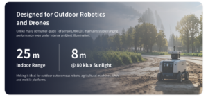
Outdoor testing should document illuminance, sun angle, direct sun entering the receiver, target reflectivity, target size, sensor orientation, temperature, and the percentage of valid pixels required. HM-LD1 is formally specified for 0.2–8 m outdoors, and the available product information refers to clear-day illumination of approximately 80,000 lux. Its formal indoor range is 0.5–25 m.
Treat the 8 m value as an operating-envelope reference, not a promise that every object will be detected at 8 m. Validate the sensor with the actual materials, dimensions, angles, speeds, and mounting geometry expected in service.
Surface Reflectivity and Geometry
Hard targets include matte black objects, polished metal, retroreflective materials, glass, water, wires, foliage, and surfaces seen at a grazing angle. A large, perpendicular, light-colored target generally returns more usable energy than a small, dark, sharply angled object.
Dust, Fog, Rain, and Multipath
Dust, rain, fog, condensation, and dirty optical windows can scatter emitted light, reduce useful range, or create uncertain returns. Glass and reflective surfaces can produce multipath, where the light reaches the detector after following an indirect path. Ask how the sensor marks invalid points and whether confidence information is available.
Temperature and Enclosure Design
HM-LD1 lists an operating-temperature range of −20°C to 60°C. That is not the same thing as an ingress-protection, shock, vibration, condensation, washdown, or EMC rating. Those ratings are not provided in the supplied specification data. Outdoor and industrial users should request them or design a suitable enclosure that does not clip the field of view or create internal reflections.
Hardware, Data, and Software Integration
Mechanical Integration
Use a rigid, repeatable mount and document the sensor coordinate frame relative to the robot, drone, camera, or machine. Keep the full optical field clear. Provide strain relief, and prevent nearby surfaces from reflecting emitted light into the receiver. The installation should allow cleaning, service, and recalibration.
Do not place the module behind unverified glass or plastic. A protective window can attenuate the outgoing and returning signal, create false close-range reflections, distort the field, or generate multipath. Test the final material, coating, thickness, spacing, and angle intended for production.
Electrical Integration
The 1.2 W power specification does not define input voltage, startup current, peak current, connector, pinout, grounding, logic levels, polarity protection, or EMC behavior. Confirm those details from current technical documentation before designing a regulator, harness, or production PCB.
Data and Calibration Integration
Verify depth units, coordinate orientation, intrinsic calibration, extrinsic calibration, timestamps, synchronization, confidence information, network settings, and firmware identification. With UDP, define the response to missing or out-of-order packets. When fusing sensors, each stream needs a known transform and dependable time base.
Operating Systems and Development Platforms
HM-LD1 is described as supporting SDKs for Windows x86, Linux x86, and ARM Linux. UART, UDP, and UVC interfaces can support PCs, Raspberry Pi-class computers, embedded Linux hosts, and flight controllers when electrical compatibility, bandwidth, and software support are available.
Do not assume native ROS or ROS 2 support unless a maintained official driver is confirmed. SDK output can be wrapped in a custom node and published as a depth image or projected point cloud. OpenCV can process organized depth frames, while calibrated XYZ data can be used with point-cloud libraries and robotic middleware.
LiDAR is often combined with GNSS, IMUs, wheel odometry, or visual positioning. For examples from the broader positioning ecosystem, see u-blox. This contextual reference does not imply endorsement of HM-LD1.
HM-LD1 Solid-State 3D LiDAR Specifications
The DTOF Solid State LiDAR HM-LD1 is a compact SPAD dToF module designed to generate real-time depth images and 3D point-cloud data. Listed applications include robot navigation, obstacle avoidance, distance measurement, UAV altitude hold, terrain following, smart inspection, robotic vision, autofocus assistance, presence detection, object recognition, volume measurement, and intrusion-zone monitoring.
Its strongest likely fit is a compact machine where low weight, low power, fixed-field depth sensing, and multiple host interfaces matter more than dense long-range reconstruction. The 40 × 30 output provides 1,200 sensing positions per frame, and the 60° × 45° field covers a broad fixed volume. The 10 fps frame rate and modest depth resolution need careful evaluation for fast vehicles, narrow hazards, and detailed inspection.
| Specification | HM-LD1 Value | Buying Interpretation |
|---|---|---|
| Sensor technology | Solid-state SPAD dToF | Fixed-field depth sensing without an external rotating scanner |
| Dimensions | 43.5 mm × 30 mm × 26.5 mm | Formal table value; verify against the latest mechanical drawing |
| Weight | 28 g | Relevant to payload-sensitive robots and UAVs |
| Indoor ranging capability | 0.5–25 m | Longer usable range under indoor or lower-ambient-light conditions |
| Outdoor ranging capability | 0.2–8 m | Validate in actual sunlight with representative targets |
| Ranging accuracy | ±3 cm | Request applicable target, range, lighting, and statistical conditions |
| Field of view | 60° horizontal × 45° vertical | Broad fixed coverage for obstacle zones, terrain, and presence sensing |
| Specification | HM-LD1 Value | Buying Interpretation |
|---|---|---|
| Depth resolution | 40 × 30 | 1,200 sensing positions per frame before invalid-point handling |
| Frame rate | 10 fps | Nominal 100 ms frame interval; complete system latency will be higher |
| Interfaces | UART, UDP, UVC | Supports serial, network, and compatible USB host workflows |
| Operating temperature | −20°C to 60°C | Separate from IP, shock, vibration, and condensation protection |
| Power consumption | 1.2 W | Low-power profile; voltage and peak-current requirements still require confirmation |
| SDK platforms | Windows x86, Linux x86, ARM Linux | Suitable for PC development and common embedded Linux architectures |
| Output applications | Depth image and 3D point cloud | Supports obstacle, terrain, zone, and spatial-measurement workflows |
Product Integration and Supplier Support
The product information describes SDK availability across several processor architectures and operating systems, along with integration support. It also states that the supplier has an independent R&D team, in-house production, stable supply, and OEM or ODM capabilities. Those claims may be valuable, but buyers should convert them into written deliverables, revision-control rules, acceptance criteria, lead times, support terms, and lifecycle commitments.
HM-LD1 may connect to PCs, Raspberry Pi-class platforms, embedded hosts, and flight controllers when the electrical and software requirements are satisfied. Potential uses include navigation support, obstacle detection, SLAM assistance, terrain following, altitude hold, robotic vision, volume measurement, presence detection, object recognition, autofocus assistance, and intrusion-zone monitoring.
Technical buyers can also review the DTOF SSL HM-LD1 product brochure before beginning detailed integration.
View Product Details & Pricing ➔
Step-by-Step Sensor Selection Workflow
1. Define the Smallest Critical Target
Start with the hazard, not the brochure. Document the minimum width, height, shape, reflectivity, and orientation of every object the machine must detect. A sensor that sees walls and people may still miss cables, branches, pallet forks, dark bumpers, or narrow structural edges.
2. Calculate Required Detection Distance
Combine maximum speed, sensor latency, transport time, algorithm time, controller reaction, braking or maneuvering distance, and safety margin. The machine’s motion and risk model should determine the required sensor range, not the other way around.
3. Map the Required Field of View
Model the sensing volume using mounting height, tilt, machine width, turn radius, terrain, landing geometry, and possible chassis or propeller occlusion. Confirm that the close-range blind zone does not overlap the bumper, floor, landing area, or working envelope.
4. Determine Necessary Spatial Detail
Estimate how many sensing positions intersect the smallest critical target at the farthest required distance. If the target occupies fewer than one or two cells, reliable detection may require more resolution, a narrower field, closer mounting, several sensors, or another sensing technology.
5. Match Frame Rate to Motion
Calculate distance traveled between frames and during complete end-to-end latency. A nominal 10 fps rate may be acceptable for slow automation, zone monitoring, altitude measurement, or terrain following. Fast forward motion requires much more careful analysis.
6. Review Worst-Case Environmental Conditions
List maximum sunlight, temperature extremes, vibration, dust, precipitation, electromagnetic noise, reflective surfaces, dark materials, and difficult target angles. A sensor that only works on the lab bench is not ready for the machine.
7. Verify Host and Interface Compatibility
Confirm that the host can power the module and receive, decode, timestamp, process, and store its output within the latency budget. Check connectors, voltage levels, cable limits, bandwidth, drivers, processor load, and recovery after a communication fault.
8. Build an On-Machine Proof of Concept
Mount the sensor in the proposed location and test actual targets, speeds, sunlight, vibration, covers, and software. Do this before committing to tooling, safety logic, production wiring, or a large order.
Testing and Validation Before Deployment
A structured acceptance test is more useful than watching a point cloud move on a screen. Laboratory work should measure static accuracy at several distances, repeated-measurement variation, warm-up behavior, thermal drift, close-range blind zones, flat-wall uniformity, edge behavior, packet stability, frame-rate consistency, and timestamp quality.
Test white matte material, dark matte material, reflective metal, angled surfaces, thin obstacles, moving people, vegetation when relevant, and wet or transparent materials when they may appear in service. The purpose is not to prove that every difficult target is always measurable. The purpose is to identify limitations and design a predictable response.
Environmental validation should cover indoor lighting, outdoor shade, direct daylight, sun near the field of view, expected temperature extremes, operational vibration, motor-generated electrical noise, and safely reproducible dust or mist. Any production cover or optical window should be installed during the test.
System testing must measure the full event-to-action chain: the event occurs, the sensor captures it, the host receives the data, the algorithm identifies the condition, the controller issues a command, and the machine slows, turns, brakes, or stops. Record valid-pixel percentage, false positives, missed detections, latency distribution, and communication-interruption behavior. Average latency by itself is not enough; tail latency matters on moving machinery.
Supplier and Lifecycle Evaluation
A capable sensor can still put a project at risk if documentation, firmware control, manufacturing consistency, or long-term supply is weak. Supplier qualification belongs in the engineering process, not in a separate purchasing silo.
- ⚙️ Request a current mechanical drawing and optical keep-out information.
- ⚙️ Confirm voltage, pinout, connector, cable, grounding, and startup-current requirements.
- ⚙️ Ask whether calibration parameters are supplied for each unit.
- ⚙️ Verify depth units, coordinate frames, timestamps, and packet documentation.
- ⚙️ Determine whether SDK examples or source-level integration samples are available.
- ⚙️ Ask whether an official ROS or ROS 2 driver exists and who maintains it.
- ⚙️ Document firmware identification, update procedures, and compatibility policies.
- ⚙️ Confirm sample lead time, production lead time, and minimum order quantity.
- ⚙️ Request product-change and end-of-life notification policies.
- ⚙️ Confirm warranty, return, repair, and failure-analysis procedures.
- ⚙️ Request available IP, shock, vibration, EMC, and compliance reports.
- ⚙️ Define the cost, ownership, scope, and lead time of OEM or ODM changes.
Claims about in-house research, direct manufacturing, stable supply, customization, and technical support can have real commercial value. In the shop, however, verbal promises do not control production. Put the requirements into written specifications, controlled drawings, acceptance tests, revision notices, and supply agreements.
3D LiDAR Sensor Buying Checklist
- ✅ Define indoor, outdoor, daytime, and nighttime operating conditions.
- ✅ Specify minimum and maximum usable range, not nominal range alone.
- ✅ Identify the smallest, darkest, thinnest, and most sharply angled critical target.
- ✅ Calculate stopping or maneuvering distance at maximum platform speed.
- ✅ Include sensor, processing, communication, controller, and actuator latency.
- ✅ Confirm horizontal and vertical coverage after mounting.
- ✅ Estimate target coverage using angular sampling and distance.
- ✅ Verify frame rate in the intended interface and output mode.
- ✅ Confirm accuracy conditions, confidence definitions, and invalid-point behavior.
- ✅ Check sensor, bracket, cable, cover, and processor mass.
- ✅ Confirm input voltage, peak current, grounding, and thermal requirements.
- ✅ Select UART, UDP, UVC, or another interface around the host architecture.
- ✅ Verify timestamps, coordinate frames, calibration, byte order, and depth units.
- ✅ Confirm SDK, operating-system, and processor compatibility.
- ✅ Check IP, shock, vibration, condensation, and EMC requirements.
- ✅ Test dark, reflective, angled, transparent, thin, and moving targets.
- ✅ Validate performance in actual sunlight and expected weather.
- ✅ Review firmware control, support, lead time, and lifecycle policy.
- ✅ Complete an on-machine proof of concept before production commitment.
The best 3D LiDAR sensor is the one that maintains enough valid data across the machine’s real operating envelope. It is not necessarily the sensor with the longest nominal range, largest point count, or widest field of view.
Final Recommendation
Select a 3D LiDAR sensor from the application backward. Begin with the smallest critical target, required detection distance, speed, stopping behavior, environment, mounting position, and processing hardware. Only then compare range, accuracy, spatial resolution, field of view, frame rate, interfaces, weight, power, software, and supplier support.
HM-LD1 is a relevant candidate for compact systems that need lightweight, low-power, fixed-field 3D sensing. Its 28 g mass, 1.2 W consumption, 60° × 45° field, UART/UDP/UVC interfaces, and multi-platform SDK support line up with obstacle-zone detection, terrain awareness, altitude sensing, presence monitoring, robotic vision, and embedded prototyping.
Its 40 × 30 resolution and 10 fps output require careful validation for small targets, detailed reconstruction, or fast forward motion. Outdoor operation must be tested with representative targets in real sunlight. Mechanical designers should verify the current dimensional drawing because the supplied product materials contain conflicting values.
Do not treat the operating-temperature range as an ingress or environmental rating, and do not use the module as a certified safety device without the appropriate documentation and architecture. Review the DTOF Solid State LiDAR HM-LD1 and download the product brochure before beginning mechanical, electrical, or software integration.
Request Your Trial Sample (Exclusive Discount Code Included)
Are you developing the next generation of autonomous mobile robots (AMRs), delivery drones,or smart automation systems? Whether you are a fast-growing startup, an established engineering firm, or leading a specialized robotics project, finding high-precision sensors that fit your budget shouldn’t be your biggest hurdle.
At MyRobotProject.com, we believe exceptional perception technology should be accessible to projects of every size. To help you accelerate your prototype development and field testing,we are opening an exclusive discount program for first-time sample orders of our dTOF Solid-State Lidar Sensors.
Why Choose Our dTOF Solid-State Lidar?
Direct Time-of-Flight (dTOF) solid-state technology offers the reliability, speed, and precision needed for high-performance spatial awareness without the mechanical wear-and-tear of traditional rotating Lidar sensors.
Decent Quality Under Budget: Premium-grade performance engineered to respect your Bill of Materials (BOM) constraints.
Solid-State Reliability: Built for long service life, shock resistance, and demanding operational environments.
Versatile Applications: Ideal for obstacle avoidance, precision hovering, mapping, and micro-navigation in robotics and drone platforms.
Claim Your First-Trial Sample Order Discount
We want to empower your development cycle right from day one. If you are ordering your very first trial sample, we are offering an exclusive online introductory discount tailored to your project scope.
How to Apply:
Send an Email to [email protected]
Include the Following Details:
Your Company / Firm Name (or Project Name)
Your Estimated Project Quantity / Target Volume
Mention that this is your very first trial order
Include Promo Code: MRP-202607 in your subject line or email body.
Fast-Track Guarantee: Our technical sales team will review your project details and respond with your customized discount quote in less than 24 hours.
Ready to Build?
Don’t let budget constraints slow down your technical validation. Reach out today with code MRP-202607 and let’s bring your robot or drone project to life!
Full LiDAR setups are powerful — but often too heavy, too complex, or just …
Frequently Asked Questions
Will this 3D LiDAR sensor work reliably outdoors in bright sunlight?
Is 40 × 30 resolution sufficient for robot navigation and obstacle avoidance?
How difficult is it to integrate HM-LD1 with existing robot hardware and software?
Can a low-resolution 3D LiDAR sensor be used for SLAM?
Does ±3 cm accuracy mean every point is always within 3 cm of the true distance?
How should frame rate be evaluated for a moving robot or drone?
Can HM-LD1 replace a certified industrial safety scanner?
What is the difference between UART, UDP, and UVC integration?
How should multiple 3D LiDAR sensors be mounted on one machine?
What should be checked before placing the sensor behind a protective window?
📚 References & Further Reading
- Industry Standard: South Survey geospatial and surveying ecosystem
- Industry Standard: u-blox positioning technology ecosystem
- Related Guide: VIO, VINS, and VSLAM Troubleshooting Guide
- Related Guide: LiDAR and Drones Beginner-Friendly Guide
- Related Guide: dToF LiDAR Imagery Explained: Depth Maps
- Product Information: DTOF Solid State LiDAR HM-LD1
- Technical Brochure: HM-LD1 Product Brochure






