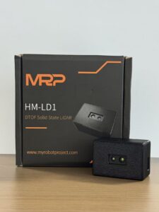
That’s where Direct Time-of-Flight (dToF) tech, specifically in solid-state builds like the LiDAR Sensor HM-LD1, changes the game. By ditching the rotating parts and moving to Single-Photon Avalanche Diode (SPAD) arrays, we’re looking at ±3cm accuracy and a 25-meter reach. You get the precision without the “ticking clock” of mechanical failure. This guide breaks down the nuts and bolts of dToF LiDAR and how you actually integrate this gear into a working robotic ecosystem that won’t flake out on you in the field.
Table of Contents
- 👉 The Physics of Perception: How dToF Solid-State LiDAR Works
- 👉 Overcoming Ambient Light: The 80,000 Lux Challenge
- 👉 HM-LD1 Solid-State LiDAR: Industrial Technical Specifications
- 👉 Deep Dive into Integration: SDKs and Platform Compatibility
- 👉 Strategic Use Cases: From UAVs to Smart Inspections
- 👉 Frequently Asked Questions on LiDAR Integration
The Physics of Perception: How dToF Solid-State LiDAR Works
In the world of optical measurement, Direct Time-of-Flight (dToF) is pretty much the gold standard. Here’s the deal: whereas Indirect Time-of-Flight (iToF) tries to guess distance by measuring the phase shift of a wave, a lidar sensor using dToF is much more straightforward. It fires a discrete light pulse and literally clocks how long it takes to hit a surface and bounce back. It’s cleaner, faster, and much better for long-range work because you can shove more peak power into that single pulse. That pulse can punch through dust and atmospheric noise that would make an iToF sensor choke.
The HM-LD1 uses what’s called a SPAD array. Think of this as a grid of incredibly sensitive photon counters. When the laser fires, the SPADs are sitting there ready to catch that return trip. Since it can pick up even a single photon, the response time is blazing. But the real kicker for those of us on the shop floor is the “solid-state” part. There are no spinning mirrors, no motors, and nothing to wear out. If you’re mounting this on a piece of heavy machinery or a drone that’s going to take some bumps, you want zero moving parts. High-vibration environments like construction sites or busy factory floors eat traditional spinning sensors for breakfast, and that’s why industry leaders like RoboSense are leaning so hard into solid-state designs for the next generation of industrial safety.
Overcoming Ambient Light: The 80,000 Lux Challenge
If you’ve ever tried to use a cheap IR sensor outside at noon, you know the struggle. The sun is basically a giant infrared noise machine that “blinds” most sensors. We call it the 80,000 lux challenge—that’s the intensity of direct summer sun. Most lidar sensor options get swamped by that background noise, giving you “ghost” readings or just failing entirely. To fix this, you need more than just a bright laser; you need smart math.
The HM-LD1 deals with this using something called time-correlated single-photon counting (TCSPC). It’s a fancy way of saying the sensor knows exactly which photons belong to its own laser and which ones are just solar interference. While it can hit 25 meters indoors or at night, it still maintains a rock-solid 8-meter range in high noon sun. That’s enough to keep a drone from clipping a bridge during an inspection or an AGV from running off an outdoor loading dock. It keeps that ±3cm accuracy regardless of whether you’re in a dim warehouse or an open field, which is exactly what you need for a reliable spatial map.
HM-LD1 Solid-State LiDAR: Industrial Technical Specifications
The HM-LD1 isn’t some hobbyist toy; it’s a module built for guys who need real data in a small package. If you’re designing for tight spaces or payload-sensitive drones, these numbers matter. The specs below aren’t just marketing fluff—they’re the hard limits you need to know for your build.
Physical and Ranging Dimensions
| Feature | Specification | Engineering Significance |
|---|---|---|
| Dimensions | 43.5mm * 30mm * 26.5mm | Squeezes into small internal bays without a sweat. |
| Ranging Capability | Indoor: 0.5-25m; Outdoor: 0.2-8m | Works anywhere from a tight corridor to a shipyard. |
| Ranging Accuracy | ±3cm | Tight enough for precision docking and safety stop zones. |
| FOV | 60°(H) x 45°(V) | Wide horizontal spread for total frontal coverage. |
| Weight | 28g | Lighter than a AA battery. Perfect for flight time. |
Optical and Electrical Characteristics
| Property | Detail | Integration Outcome |
|---|---|---|
| Resolution | 40 * 30 (1,200 points) | Good density without melting your CPU. |
| Frame Rate | 10fps | Keeps up with walking speeds and drone drift. |
| Interface | UART / UDP / UVC | Talks to everything from Arduinos to PCs. |
| Operating Temp | -20 ℃ – 60 ℃ | Handles freezing mornings and sweltering shops. |
| Power Consumption | 1.2 W | Won’t kill your battery or overheat your casing. |
View Product Details & Pricing ➔
The HM-LD1 is a pro-grade sensing tool straight from the factory. That means you get a stable supply chain and consistent quality, which is vital for B2B procurement. If you’re working on something really specialized that needs custom optics or a specific housing, these guys can actually customize the units. It’s a lot better than trying to make a consumer-grade hobby sensor work in a professional environment.
Deep Dive into Integration: SDKs and Platform Compatibility
Hardware is only half the battle. If the software sucks, the sensor is just a paperweight. The HM-LD1 fixes the “integration bottleneck” by supporting multiple protocols out of the box. Whether you’ve got a Windows-based IPC doing heavy lifting or an ARM-based Pi running a drone, you’re covered. Here’s what you need to know about the pipeline:
1. Communication Protocols: UART, UDP, and UVC
You’ve got options here, depending on your build.
✅ UVC (USB Video Class): This makes the lidar sensor show up like a webcam. It’s the fastest way to get a point cloud onto a PC for testing.
✅ UART: If you’re on a microcontroller and every millisecond of latency counts, go serial.
✅ UDP: For bigger rigs where you might have three or four sensors networked together over Ethernet. Direct, robust, and industry-standard.
2. Cross-Architecture SDK Support
The SDKs are ready for x86 (Windows/Linux) and ARM (Linux). That’s big because it means you can develop your navigation logic on a high-powered workstation and push it straight to an edge device like a Jetson Nano without rewriting your data parsing. The SDK takes the raw SPAD photon events and spits out usable 3D coordinates (X, Y, Z). It saves you from having to do the heavy math yourself so you can focus on the actual robot behavior.
Strategic Use Cases: From UAVs to Smart Inspections
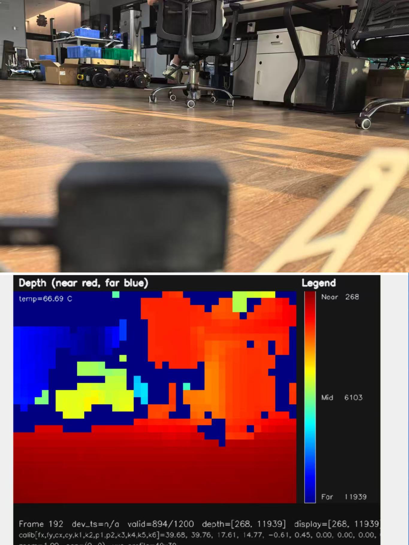
Since the HM-LD1 gives you a full depth image (40×30 resolution) and not just a single distance reading, it’s basically an electronic “eye.” It sees volume, not just points. Here is where it’s being used right now:
- ⚙️ UAVs & Drones: In flight, weight is everything. At 28g, this sensor allows for terrain following and altitude hold with centimeter precision. Agricultural drones use this to stay exactly three feet above uneven crops, and indoor drones use it to navigate rafters without a pilot.
- ⚙️ Robotic Navigation (SLAM): For AGVs, the 60° FOV acts like a “safety curtain.” If you put these on the corners of a robot, it’ll see low-profile stuff like pallet forks or hanging wires that a standard 2D laser scanner would miss because they’re too high or too low.
- ⚙️ Smart Security: Unlike a camera, LiDAR doesn’t record faces, so it’s great for privacy. It can track people moving through a zone and trigger an alarm based on volume and movement within a 25m radius without any GDPR or privacy headaches.
- ⚙️ Industrial metrology: It’s being used on conveyor belts to measure the volume of packages in real-time. This helps optimize warehouse sorting and ensures no oversized boxes jam the works.
Frequently Asked Questions on LiDAR Integration
What is the real difference between a laser distance sensor and single-point LiDAR for robotics?
Why is dToF LiDAR better than traditional sensing (iToF or Ultrasonic) for outdoor robots?
How can I find a cost-effective LiDAR sensor that isn’t a toy?
📚 References & Further Reading
- Industry Standard: RoboSense Solid State Comparison
- Product Resource: DTOF SSL HM-LD1 Product Brochure & Datasheet
- Related Guide: Explore the Full HM-LD1 Technical Specifications