


Drone with LiDAR Sensor: Lightweight 3D Perception for UAVs
A drone with LiDAR sensor technology can measure distance directly instead of trying to infer depth from a conventional image. Here’s the deal: that distinction matters whenever a UAV has to hold altitude over uneven ground, detect an approaching structure, maintain a safe stand-off distance, or navigate through a place where satellite positioning and visual texture are unreliable.
That does not mean every LiDAR module is automatically a good fit for an aircraft. In the shop, the practical questions usually come down to payload mass, power draw, field of view, update rate, mounting geometry, data latency, sunlight performance, target reflectivity, vibration, and the behavior of the complete aircraft under real operating conditions.
The best UAV LiDAR is rarely the unit with the longest number on the product page. It is the sensor whose useful range, coverage, interfaces, processing requirements, environmental limits, and failure behavior match the mission. A short-range depth sensor may be a very good choice for altitude hold or close inspection, while a survey payload requires an entirely different system architecture.
This guide explains how drone LiDAR works, where compact solid-state dToF technology fits, how to evaluate indoor and outdoor performance, and how to integrate the 28 g HM-LD1 with flight controllers, Raspberry Pi systems, Jetson computers, PCs, and other embedded platforms.
Sharing a compact dToF sensor we’ve been working with for drone obstacle av…
Featured compact UAV depth sensor: The DTOF Solid State LiDAR HM-LD1 provides 40 × 30 depth resolution, a 60° × 45° field of view, 10 fps output, UART/UDP/UVC interfaces, and outdoor daytime ranging up to 8 m under suitable conditions.
Table of Contents
- ✅ What Is a Drone with LiDAR Sensor?
- ✅ How Drone LiDAR Measures Distance
- ✅ LiDAR vs Cameras, Ultrasonic Sensors, and Radar
- ⚙️ How to Select LiDAR for a UAV
- ⚙️ HM-LD1 Specifications for Drone Integration
- ⚙️ Range, Sunlight, Reflectivity, and Environmental Performance
- ⚙️ Field of View, Resolution, and Frame Rate
- ⚙️ Weight, Power, and Flight-Time Impact
- ⚙️ Mechanical and Electrical Integration
- ⚙️ Software, Point-Cloud, and Depth-Map Integration
- ✅ Drone LiDAR Applications
- ⚙️ Flight Testing and Validation
- ⚙️ Limitations and Engineering Trade-Offs
- ⚙️ Drone LiDAR Buying Checklist
- ✅ Selecting a Practical UAV Depth Sensor
- ✅ Frequently Asked Questions
What Is a Drone with LiDAR Sensor?
A drone with LiDAR sensor hardware carries an active optical ranging system. It emits light, receives some of the reflected energy, and calculates the distance to a target. Depending on the product design, the result may be a single range value, a multi-zone depth image, or a point cloud. The key point is that the sensor is measuring geometry rather than merely recording brightness and color.
UAV LiDAR systems generally fall into two practical groups. The first group includes mapping payloads built around scanners, GNSS receivers, inertial measurement units, precise timing, calibration, trajectory processing, and georeferencing software. These systems are intended for surveying, corridor mapping, forestry, construction documentation, and other applications where the final data must be tied to a global coordinate system.
The second group consists of compact perception sensors. These modules are used for nearby obstacle detection, altitude hold, terrain following, indoor navigation, landing assistance, robotic vision, and inspection stand-off control. They can describe local geometry in the sensor frame, but they do not automatically produce a survey-grade map.
Important distinction: A compact depth LiDAR can help a drone perceive nearby geometry, but it does not by itself provide globally referenced maps. Georeferenced mapping normally requires position, orientation, calibration, and synchronized sensor data in addition to LiDAR measurements.
The HM-LD1 belongs primarily in the local-perception category. Its 40 × 30 depth output gives an embedded system a view of nearby surfaces and obstacles. That makes it useful for practical UAV experiments and close-range autonomy, provided the aircraft is designed around its actual range and update characteristics.
How Drone LiDAR Measures Distance
Direct Time-of-Flight Measurement
Direct time-of-flight, or dToF, measures how long emitted light takes to travel to a target and return to the receiver. The sensor uses the speed of light and the measured round-trip interval to estimate distance. The calculation divides by two because the measured time includes both the outbound and return paths.
The HM-LD1 uses SPAD dToF technology. SPAD stands for single-photon avalanche diode. A SPAD receiver is designed to detect very small returned optical signals. Timing electronics, calibration routines, signal processing, and validity checks then convert the detected returns into useful depth values.

Why Solid-State Architecture Matters on a UAV
A solid-state module does not depend on a large externally rotating scanning assembly. On an aircraft, that can simplify packaging, reduce mechanical complexity, lower payload mass, and make it easier to install the sensor inside a protected payload bay. A fixed field of view is also easier to characterize relative to the airframe.
Look, solid-state does not automatically mean more accurate than every mechanical LiDAR. Accuracy, range, angular resolution, optical design, filtering, and environmental performance remain product-specific. The attraction of the HM-LD1 is the combination of local area coverage, low module mass, modest power consumption, and several host-interface options.
From Depth Image to Point Cloud
A depth map assigns a distance value to each valid sensing cell. Software can project those values into three-dimensional coordinates using the sensor calibration and projection model. The resulting point cloud can then be transformed into the UAV body frame and combined with attitude, position, or other perception data.
Not every cell will return a valid value in every frame. Sunlight, dark surfaces, transparent materials, occlusion, field-of-view edges, vibration, and internal filtering can all create missing measurements. Navigation software should preserve validity flags and timestamps. Treating every missing value as clear space is a serious design mistake.
LiDAR vs Cameras, Ultrasonic Sensors, and Radar
No sensor wins every UAV application. The right choice depends on range, lighting, target materials, aircraft speed, compute capacity, environmental exposure, and the consequences of a missed detection. LiDAR is valuable because it measures range directly, but it works best as part of a complete sensing architecture.
| Sensor Type | Primary Output | Typical UAV Strength | Important Limitation |
|---|---|---|---|
| LiDAR or depth sensor | Direct range, depth map, or point cloud | Geometric perception and distance measurement | Performance can vary with sunlight, reflectivity, target angle, weather, and optical contamination. |
| Monocular camera | Two-dimensional image | Rich texture, color, recognition, and low sensor mass | Metric depth generally requires motion, multiple observations, assumptions, or learned estimation. |
| Stereo camera | Images and calculated disparity | Dense depth in suitably textured scenes | Can struggle with low texture, glare, darkness, repeated patterns, and processing demand. |
| Ultrasonic sensor | One or several distance readings | Low-cost short-range altitude or proximity sensing | Broad acoustic beam, limited spatial detail, and sensitivity to airflow and surface angle. |
| Radar | Range and, depending on design, velocity or angle | Operation in difficult lighting and some adverse conditions | Resolution, antenna size, processing, and integration characteristics vary substantially. |
| GNSS and INS | Global position, orientation, and motion estimate | Outdoor navigation, trajectory estimation, and georeferencing | Does not directly perceive nearby obstacles and may be degraded in obstructed environments. |
Why Sensor Fusion Is Often Better
A LiDAR frame describes local geometry. An IMU measures angular velocity and acceleration. A camera contributes appearance and texture, while GNSS supplies a global outdoor reference. Optical flow, visual odometry, radar, and ultrasonic sensing can add motion or range information in situations where one modality becomes unreliable.
Redundancy is useful only when the software knows how to handle disagreement. Stale data, invalid returns, communication interruptions, timing offsets, and conflicting position estimates need explicit detection and defined fallback behavior. For broader positioning context, ComNav Technology provides an external reference for GNSS and navigation technologies. This reference does not imply third-party validation of the HM-LD1.
How to Select LiDAR for a UAV
1. Define the Required Detection Zone
Start with the aircraft geometry and the flight task. A downward-facing sensor may support altitude hold. A forward-facing unit is better suited to approach monitoring and obstacle detection. A forward-and-downward installation can provide information about upcoming terrain, while a side-facing sensor may help with wall or asset inspection.
Maximum range is only one part of the answer. Minimum range, blind zones, field of view, mounting angle, vehicle dimensions, and stopping distance matter just as much. A long-range unit pointed away from the hazard is not a useful safety sensor.
2. Estimate the Required Reaction Distance
The aircraft needs enough distance to acquire a frame, transmit it, process it, make a decision, send a command, and change its motion. Add braking or avoidance distance and an engineering margin. Speed, mass, thrust reserve, wind, controller tuning, and obstacle shape all affect the result.
Do not declare a universal safe speed from the HM-LD1’s 10 fps figure alone. A new frame is nominally available every 100 milliseconds, but the aircraft continues moving during that interval. The completed aircraft must be tested with its actual processor, firmware, mounting arrangement, and flight-control stack.
3. Match Range to the Operating Environment
The HM-LD1 is specified for 0.5–25 m indoors and 0.2–8 m outdoors. That difference is a useful reminder that indoor range and outdoor daytime range should be treated as separate engineering cases. Sunlight, target reflectivity, surface angle, and contamination can reduce valid measurements.
4. Establish Payload and Power Budgets
Count the module, mount, fasteners, dampers, cable, enclosure, regulator, companion computer, cooling hardware, and any additional shielding. The installed subsystem may weigh considerably more than the sensor itself. It can also shift the center of gravity or add drag.
5. Select the Data Interface
UART is often convenient for embedded serial communication. UDP can transport data to a network-capable companion computer. UVC may support imaging-oriented workflows on compatible hosts. Confirm voltage levels, packet structure, bandwidth, latency, drivers, connectors, and software support before locking in the design.
For another decision framework, review this guide on how to choose lightweight LiDAR for a UAV.
HM-LD1 Specifications for Drone Integration
DTOF Solid State LiDAR HM-LD1
The DTOF Solid State LiDAR HM-LD1 is a compact SPAD dToF module intended for embedded 3D perception. Its 28 g weight and approximately 1.2 W power consumption make it a candidate for weight-sensitive UAVs that need local ranging, depth images, or point-cloud data.
The module can provide real-time depth information for obstacle avoidance, distance detection, autonomous navigation, inspection, terrain awareness, landing assistance, and robotic-vision development. UART, UDP, and UVC interfaces give designers several ways to connect it to embedded systems, PCs, Raspberry Pi-class computers, Jetson-class computers, and compatible flight-control architectures.
| Specification | HM-LD1 Value | UAV Integration Relevance |
|---|---|---|
| Dimensions | 43.5 × 30 × 26.5 mm | Compact dimensions support integration into constrained UAV frames and payload bays. |
| Indoor ranging capability | 0.5–25 m | Relevant to enclosed spaces, warehouses, tunnels, and nighttime operation. |
| Outdoor ranging capability | 0.2–8 m | Suitable for evaluating short-range daytime perception under validated conditions. |
| Ranging accuracy | ±3 cm | Supports local distance measurement where the complete system has been calibrated and tested. |
| Field of view | 60° horizontal × 45° vertical | Provides area coverage rather than only a single ranging point. |
| Weight | 28 g | Helps limit the payload penalty on small UAV platforms. |
| Resolution | 40 × 30 | Produces 1,200 nominal depth samples per frame before invalid-point filtering. |
| Frame rate | 10 fps | Must be assessed against aircraft speed, control latency, and obstacle geometry. |
| Interfaces | UART / UDP / UVC | Supports embedded, networked, and imaging-oriented host integration. |
| Operating temperature | -20°C to 60°C | Provides the module temperature envelope; full-system thermal qualification is still required. |
| Power consumption | 1.2 W | Supports low-power payload design but still requires regulator and endurance calculations. |
Mechanical-data note: One supplied marketing paragraph lists dimensions that differ from the formal dimensions table. This article uses 43.5 × 30 × 26.5 mm because that value appears in the structured specification data. Integrators should confirm the current mechanical drawing before designing a production mount.
View Product Details & Pricing ➔
Range, Sunlight, Reflectivity, and Environmental Performance
LiDAR range is not a fixed promise that applies to every object. Ambient sunlight, target reflectivity, color, material, surface angle, atmospheric conditions, optical contamination, motion, vibration, occlusion, internal filtering, and multipath reflections can all affect whether a return is accepted.
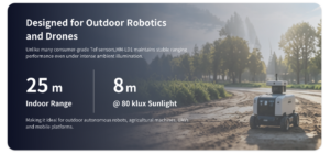
The HM-LD1 is specified for up to 25 m indoors or at night and up to 8 m outdoors in daytime under suitable conditions. The supplied product description references testing at 8 m on a clear summer day at approximately 80,000 lux. Treat that as a defined test context, not as a guarantee that every object will be detected at 8 m.
Target Reflectivity and Surface Angle
A bright, diffuse surface generally returns more usable optical energy than a dark, absorbent surface. A target angled away from the receiver may send much of the reflected energy somewhere other than back toward the sensor. Glass, water, polished metal, retroreflective materials, and complex multipath environments deserve application-specific testing.
The weakest expected target should drive the validation plan. A successful test against a large white board does not prove equivalent performance against black cable insulation, weathered concrete, vegetation, dark fabric, narrow poles, or angled steel structures.
Protective Windows and Contamination
If the module sits behind a protective cover, the window must be compatible with the optical path. Unsuitable material, coatings, thickness, internal reflections, dust, condensation, water droplets, and scratches can reduce data quality. A window can also create near-field reflections that interfere with measurements.
Do not select a window material based on guesswork. Confirm the design with current manufacturer guidance, then test the completed enclosure across the required field of view and temperature range. Include realistic contamination and cleaning procedures in the operating plan.
Field of View, Resolution, and Frame Rate
The HM-LD1 combines a 60° horizontal by 45° vertical field of view with 40 × 30 depth resolution and a 10 fps frame rate. Those values determine how much of the scene is covered, how densely it is sampled, and how often the navigation software receives new information.
Angular Coverage and Sampling Density
The 40 × 30 output represents 1,200 nominal depth cells per frame. A wide field of view spreads those cells across a broad scene. Walls, floors, roofs, and other large surfaces may occupy many cells. Wires, branches, thin poles, and object edges may occupy only a few cells or fall between sampling directions.
Objects occupy fewer samples as distance increases. Obstacle software should use spatial grouping, temporal confirmation, validity data, conservative thresholds, and appropriate safety margins. It should not assume that every hazard will produce a large continuous cluster.
Understanding 10 fps in a Moving UAV
At 10 fps, a new frame is nominally produced every 100 milliseconds before transmission, host processing, and flight-controller delays. Total response latency also includes decoding, filtering, obstacle classification, command transport, actuator response, and aircraft dynamics.
A 10 fps module may fit low-speed proximity sensing, terrain awareness, landing, or inspection tasks. It should not be declared suitable for every flight speed from frame rate alone. Test the completed system at representative speeds and calculate the distance traveled during the entire detection-to-response cycle.
Weight, Power, and Flight-Time Impact
The HM-LD1 weighs 28 g and consumes approximately 1.2 W. Those figures are attractive for compact aircraft, but they do not describe the entire installed payload.
Calculate Installed Payload Mass
Include the sensor, mount, fasteners, vibration-control components, cables, connectors, protective structure, regulator, and companion processor. Cooling hardware and electromagnetic shielding may also be necessary. Compare complete subsystem mass, not module mass alone.
Mass location matters as well. A forward-mounted unit can shift the center of gravity and increase control effort. A sensor mounted far from the aircraft center may experience greater motion during pitch and yaw. Check balance, vibration, controller tuning, and motor loading after installation.
Calculate the Complete Power Budget
The 1.2 W sensor figure does not include a Raspberry Pi, Jetson, PC, network hardware, cooling fan, or regulator losses. Confirm the required input voltage and operating modes in current integration documentation before selecting a regulator.
In the shop, the most useful endurance comparison is simple: fly the same aircraft with and without the complete perception system, using the same battery, propellers, payload, and flight profile. Log battery telemetry and hover current. That result is more valuable than a theoretical estimate based on sensor power alone.
Mechanical and Electrical Integration
Mounting Orientation and Coordinate Alignment
Downward mounting supports altitude and surface-distance measurement. Forward mounting supports approach monitoring. Forward-and-downward mounting may help with terrain transitions, while side-facing installation can assist wall or asset inspection.
Measure and record the translation and rotation between the sensor frame and the UAV body frame. A small angular error creates an increasingly large positional error with distance. Repeatable alignment is particularly important for ground-plane estimation, point-cloud accumulation, and sensor fusion.
Vibration and Structural Rigidity
The mount should preserve alignment while limiting harmful vibration. Excessive flexibility can allow the sensor to oscillate and change its viewing direction relative to the aircraft. Test the installed output across expected motor speeds, propeller conditions, payload configurations, and maneuvers.
Power and Signal Integrity
Plan for regulated power, grounding, connector retention, strain relief, noise control, and cable routing away from high-current motor wiring. UDP requires network addressing and packet handling. UART requires confirmed logic levels, serial settings, packet formats, and bandwidth. UVC behavior depends on the host and software environment.
Do not design from assumed connector pinouts or supply voltages. Consult the latest product brochure and integration documentation before wiring hardware. Incorrect logic levels, reverse polarity, and noisy power can damage equipment or produce unreliable measurements.
Host Platform Selection
SDK support is listed for x86 Windows, x86 Linux, and ARM Linux. Potential hosts include PCs, Raspberry Pi systems, Jetson systems, flight controllers, and embedded computers when the selected interface, operating system, processing capacity, and software are compatible.
Teams developing a custom embedded stack may also review the HM-RV1 RISC-V development board. This is a related embedded option, not confirmation of plug-and-play compatibility. Verify drivers, interfaces, processing performance, and software support before pairing the platforms.
Software, Point-Cloud, and Depth-Map Integration
A practical pipeline receives depth data through UART, UDP, or UVC. The host decodes range values, validity information, timestamps, and available status fields. Invalid measurements should be marked as invalid rather than silently converted to maximum range or free space.
Spatial and temporal filtering can reduce isolated noise, but filtering adds latency and can erase small objects. When a point cloud is needed, project valid depth cells into three-dimensional coordinates with the correct calibration. Then transform the points from the LiDAR frame into the UAV body frame and, when necessary, compensate using aircraft attitude.
Application software may identify obstacle clusters, ground planes, clear corridors, terrain height, or possible landing surfaces. Any command sent to a flight controller should be bounded and protected by safety checks. Log raw and processed data so engineers can separate optical limitations from timing, calibration, vibration, or control problems.
ROS and OpenCV Workflows
ROS can organize sensor messages, transforms, visualization, logging, and navigation nodes. OpenCV can support depth filtering, region analysis, morphology, segmentation, and visualization. These tools can shorten development time, but they do not eliminate the need for calibration or flight validation.
Do not assume an exact ROS package name or supported version until the current SDK and integration resources have been checked. Confirm message formats, dependencies, installation procedures, and sample applications before committing the development schedule.
Time Synchronization and Coordinate Frames
Timestamps are critical on a moving aircraft. A depth frame paired with stale attitude data can appear rotated, shifted, or distorted. Define the LiDAR optical frame, mechanical frame, UAV body frame, IMU frame, local navigation frame, and global frame when GNSS is used.
Record raw depth, validity, timestamps, attitude, position, velocity, control commands, processor load, and communication status during testing. This record helps identify whether unexpected behavior comes from the sensor, timing, calibration, vibration, or control stack.
Drone LiDAR Applications
Altitude Hold
A downward-facing depth LiDAR can estimate distance to the surface below the aircraft. A multi-zone frame lets software compare several areas and reject isolated returns instead of depending on one point. Sloped ground, vegetation, water, ledges, and rapidly changing terrain still require robust surface-selection logic and fallback behavior.
Terrain Following
Forward-and-downward depth data may help a UAV identify an approaching elevation change before it flies over it. The controller must distinguish ground from obstacles and apply conservative limits for forward speed, ascent, descent, and commanded clearance. Pitch changes also alter where the field of view intersects the terrain.
Obstacle Detection
Depth cells can be grouped into occupancy regions or compared with distance thresholds. One HM-LD1 does not provide full aircraft coverage, however. Areas outside its 60° × 45° viewing cone remain blind unless additional sensors or another perception modality is installed.
Indoor and GNSS-Denied Navigation
A depth sensor can contribute local geometry for obstacle avoidance or SLAM, but LiDAR alone does not solve localization. A complete navigation system may combine depth with an IMU, optical flow, cameras, map matching, or other motion estimates. Repetitive corridors and scenes with limited geometry can still challenge localization software.
Infrastructure Inspection
Potential targets include bridges, dams, walls, tanks, expressway structures, and industrial equipment. With outdoor ranging specified up to 8 m under suitable conditions, the HM-LD1 can be evaluated for local stand-off control, proximity measurement, and approach monitoring. It should not be presented as a replacement for a long-range geospatial survey scanner.
Landing and Surface Assessment
A depth frame may support surface-distance and geometry estimation during low-altitude approach. A complete landing-zone assessment may also need information about texture, motion, slope, vegetation, debris, people, and hazards that are not fully represented by depth alone. Combining LiDAR with camera-based classification can provide better context.
Flight Testing and Validation
Phase 1: Bench Testing
Measure known distances throughout the intended range. Test bright, dark, flat, angled, narrow, reflective, and low-return targets at the center and edges of the field of view. Verify interface stability, startup behavior, long-duration operation, invalid-data handling, and thermal behavior.
Phase 2: Installed Static Testing
Install the module on the airframe and compare readings with motors off and running. Determine whether power electronics, vibration, network traffic, cable routing, propeller airflow, or a protective window changes the output. Verify alignment and cable retention before flight.
Phase 3: Controlled Flight Testing
Begin at low speed in a controlled area. Compare LiDAR measurements with independently measured ground truth. Test hover, approach, retreat, yaw, pitch, roll, and representative obstacle orientations. Confirm that invalid or delayed data produces a safe response rather than an aggressive command.
Phase 4: Mission-Envelope Validation
Evaluate credible worst-case combinations: maximum speed, strong sunlight, low-reflectivity targets, angled surfaces, airframe vibration, temperature extremes, processor load, communication delay, contamination, and partial sensor failure. Test interactions between these variables instead of checking only ideal laboratory conditions.
Define pass-and-fail criteria before testing. Useful metrics include valid-data percentage, detection distance, false-positive rate, false-negative rate, end-to-end latency, thermal stability, recovery after communication interruption, and safe fallback behavior.
Limitations and Engineering Trade-Offs
Outdoor daytime range is shorter than indoor or nighttime range. The 40 × 30 depth output provides useful local geometry but is not a high-density survey scan. The 10 fps frame rate limits the operating envelope for high-speed obstacle response, especially after transmission, processing, and aircraft dynamics are included.
One module covers only its stated 60° × 45° field of view. Range and validity can change with material, surface angle, sunlight, weather, vibration, and contamination. The module also does not independently provide global position or a georeferenced map.
Survey-grade airborne mapping needs additional positioning, orientation, timing, calibration, trajectory estimation, and processing. Safety-critical autonomy requires fault detection, fallback behavior, system-level testing, and potentially redundant sensing.
Here’s the practical takeaway: the HM-LD1 is best evaluated as a compact local 3D perception module. Its value comes from balancing 28 g weight, 1.2 W power, multi-zone depth output, and UART/UDP/UVC connectivity. It is not intended to replace every sensor in the UAV navigation stack.
Drone LiDAR Buying Checklist
- ✅ Confirm that required minimum and maximum distances fall inside the relevant environmental range.
- ✅ Evaluate outdoor daytime range separately from indoor or nighttime range.
- ✅ Align the 60° × 45° field of view with the required detection zone.
- ✅ Test whether 40 × 30 resolution can represent the smallest safety-relevant obstacle.
- ✅ Verify that 10 fps is compatible with aircraft speed, latency, and reaction-distance requirements.
- ✅ Include the mount, cables, enclosure, regulator, and processor in the payload calculation.
- ✅ Include voltage conversion and host-computer demand in the power calculation.
- ✅ Confirm that UART, UDP, or UVC matches the intended architecture.
- ✅ Verify that the -20°C to 60°C module temperature range is adequate for the installation.
- ✅ Confirm current SDK availability for the selected operating system and processor architecture.
- ✅ Obtain the current mechanical drawing before producing the mount.
- ✅ Test dark, angled, reflective, narrow, and low-return targets.
- ✅ Confirm optical-window requirements with the manufacturer.
- ✅ Synchronize depth measurements with the IMU and flight controller where required.
- ✅ Define behavior for late, invalid, frozen, or unavailable data.
- ✅ Confirm technical integration support, supply requirements, and any OEM or ODM needs.
To discuss UAV mounting, interface selection, depth-data processing, or customized integration, review the HM-LD1 product page. Give the engineering team the aircraft type, expected speed, required detection zone, ambient-light conditions, host platform, preferred interface, and environmental requirements.
Selecting a Practical UAV Depth Sensor
A drone with LiDAR sensor hardware gains direct local depth information that can support altitude hold, terrain following, obstacle detection, landing assistance, and inspection workflows. Successful deployment depends on more than maximum range. The engineer must match field of view, resolution, frame rate, outdoor behavior, weight, power, interface, processing latency, calibration, and failure behavior to the mission.
With a weight of 28 g, power consumption of approximately 1.2 W, 40 × 30 depth resolution, 10 fps output, and UART/UDP/UVC connectivity, the HM-LD1 offers a compact starting point for UAV 3D perception. Confirm suitability through representative bench tests and controlled flight trials, especially in bright sunlight and against low-reflectivity, narrow, or angled targets.
Request Your Trial Sample (Exclusive Discount Code Included)
Are you developing the next generation of autonomous mobile robots (AMRs), delivery drones,or smart automation systems? Whether you are a fast-growing startup, an established engineering firm, or leading a specialized robotics project, finding high-precision sensors that fit your budget shouldn’t be your biggest hurdle.
At MyRobotProject.com, we believe exceptional perception technology should be accessible to projects of every size. To help you accelerate your prototype development and field testing,we are opening an exclusive discount program for first-time sample orders of our dTOF Solid-State Lidar Sensors.
Why Choose Our dTOF Solid-State Lidar?
Direct Time-of-Flight (dTOF) solid-state technology offers the reliability, speed, and precision needed for high-performance spatial awareness without the mechanical wear-and-tear of traditional rotating Lidar sensors.
Decent Quality Under Budget: Premium-grade performance engineered to respect your Bill of Materials (BOM) constraints.
Solid-State Reliability: Built for long service life, shock resistance, and demanding operational environments.
Versatile Applications: Ideal for obstacle avoidance, precision hovering, mapping, and micro-navigation in robotics and drone platforms.
Claim Your First-Trial Sample Order Discount
We want to empower your development cycle right from day one. If you are ordering your very first trial sample, we are offering an exclusive online introductory discount tailored to your project scope.
How to Apply:
Send an Email to [email protected]
Include the Following Details:
Your Company / Firm Name (or Project Name)
Your Estimated Project Quantity / Target Volume
Mention that this is your very first trial order
Include Promo Code: MRP-202607 in your subject line or email body.
Fast-Track Guarantee: Our technical sales team will review your project details and respond with your customized discount quote in less than 24 hours.
Ready to Build?
Don’t let budget constraints slow down your technical validation. Reach out today with code MRP-202607 and let’s bring your robot or drone project to life!
Frequently Asked Questions About Drones with LiDAR Sensors
Can a drone with LiDAR sensor work reliably outdoors in bright sunlight?
Will adding a LiDAR sensor reduce drone flight time because of its weight and power consumption?
Is integration difficult with flight controllers, Raspberry Pi, or Jetson systems?
Can the HM-LD1 be used for aerial LiDAR mapping?
What size obstacle can a 40 × 30 LiDAR depth sensor detect?
Can one LiDAR module support both altitude hold and terrain following?
Which interface should a UAV developer choose: UART, UDP, or UVC?
Can the LiDAR operate in rain, fog, dust, or snow?
Does a drone LiDAR need calibration after mounting?
Can HM-LD1 be the only obstacle-avoidance sensor on an autonomous drone?
📚 References & Further Reading
- ✅ Industry Standard: ComNav Technology positioning and navigation resources
- ✅ Related Guide: How to choose lightweight LiDAR for a UAV
- ✅ Localization Guide: Precise robot localization made easy
- ✅ Product Documentation: DTOF SSL HM-LD1 product brochure






