LiDAR from Drone: How to Choose a Lightweight UAV LiDAR Sensor for Mapping, Navigation, and Obstacle Avoidance
Putting LiDAR from drone platforms into real industrial use is not just a matter of buying a sensor, bolting it under an airframe, and calling the job done. Here’s the deal: a UAV LiDAR system has to balance ranging distance, payload weight, power consumption, field of view, frame rate, interface, vibration, sunlight performance, onboard compute, software compatibility, and the actual mission objective. A drone used for large-area 3D mapping may need a very different LiDAR payload than a compact UAV used for warehouse inspection, landing assistance, obstacle avoidance, bridge observation, or terrain following.
This guide walks through how drone LiDAR works, how it compares with photogrammetry, which specifications matter most, and how to evaluate lightweight LiDAR modules for embedded UAV perception. It also introduces the DTOF Solid State LiDAR HM-LD1 – DTOF SSL as a practical example of a compact dToF solid-state LiDAR module designed for real-time depth imaging and 3D point cloud output, with a listed weight of 28 g, 1.2 W power consumption, UART/UDP/UVC interfaces, and SDK support for x86 Windows, x86 Linux, and ARM Linux.
Table of Contents
- 👉 What Does “LiDAR from Drone” Mean?
- 👉 How Drone LiDAR Works
- 👉 Drone LiDAR vs Drone Photogrammetry
- 👉 Main Applications: Mapping, Navigation, and Obstacle Avoidance
- 👉 Types of LiDAR Sensors Used on Drones
- 👉 Key Specifications When Choosing a UAV LiDAR Sensor
- 👉 Integration Workflow for Drone LiDAR Systems
- 👉 Lightweight UAV LiDAR Example: HM-LD1 dToF Solid-State LiDAR
- 👉 Drone LiDAR Selection Checklist
- 👉 Common Mistakes When Using LiDAR from Drone Platforms
- 👉 Frequently Asked Questions About LiDAR from Drone Systems
What Does “LiDAR from Drone” Mean?
The phrase LiDAR from drone means using a drone-mounted LiDAR sensor to measure distance, create depth information, collect point cloud data, or support real-time perception tasks. In plain shop-floor language, the drone is carrying a laser-based distance sensor and using that data to understand the space around it. That can mean airborne terrain mapping, UAV inspection, drone obstacle avoidance LiDAR, altitude hold, landing assistance, autonomous navigation, SLAM research, and 3D perception for robotics. The important part is this: the engineering requirements change fast depending on what the drone has to do.
A survey drone flying over a forest canopy, quarry, construction site, or powerline corridor may require a high-end scanning LiDAR payload synchronized with GNSS and inertial measurement data. That type of system is usually designed to produce dense, georeferenced point clouds for post-processing and measurement. By contrast, a small UAV flying indoors, near shelves, around bridge structures, or inside industrial spaces may need a compact UAV LiDAR module that outputs real-time depth maps or point clouds for obstacle awareness and local navigation.
Look, this distinction matters because many buyers search for “drone LiDAR sensor” while comparing two very different product categories. The first category is the surveying-grade drone LiDAR payload, which often prioritizes long-range mapping density, georeferencing accuracy, and post-processing workflows. The second category is the lightweight LiDAR for drones, which prioritizes weight, power, field of view, frame rate, interface compatibility, SDK support, and real-time output. A compact solid-state LiDAR module may not replace a high-end airborne survey payload, but it can be extremely useful for short-range measurement, obstacle avoidance, terrain following, landing assistance, and embedded robotics development.
How Drone LiDAR Works
Basic Principle of Time-of-Flight Measurement
LiDAR measures distance by emitting light and analyzing the returned signal after it reflects from a surface. In a direct time-of-flight system, the sensor estimates distance from the travel time of light between emission and return. The shorter the travel time, the closer the object; the longer the travel time, the farther the object. For a general background on the physics behind distance measurement by travel time, see this overview of time of flight.
In drone applications, that simple ranging idea gets complicated because the sensor is bolted to a moving platform. The drone may roll, pitch, yaw, accelerate, vibrate, and change altitude while the LiDAR is collecting data. So the raw distance number is only one part of the job. Engineers also have to think about sensor orientation, timestamps, coordinate frames, mounting angle, and synchronization with the flight controller, IMU, camera, or onboard computer.
In the shop, this is where clean integration separates a prototype from a tool you can trust. A LiDAR module can report a perfectly valid distance in its own local coordinate frame, but if the drone is pitched forward ten degrees or vibrating hard near the motor band, the autonomy stack still has to interpret that measurement correctly. Otherwise, the drone may think an obstacle is lower, higher, closer, or farther than it really is.
What a Drone LiDAR System Outputs
Drone LiDAR systems can output different kinds of data. Some simple ranging sensors provide single distance readings. More advanced 2D LiDAR systems provide scan lines. 3D LiDAR and depth LiDAR modules may output depth maps, range images, 3D point clouds, or obstacle zones. Compact dToF LiDAR modules often provide lower-resolution but real-time depth images that are useful for embedded perception. Survey-grade payloads may generate much denser georeferenced point clouds for terrain models, asset inspection, vegetation analysis, and construction measurement.
For UAV autonomy, real-time output can be more important than point density. A drone avoiding a wall, entering a warehouse aisle, or following terrain needs fast and reliable distance awareness. The system has to convert LiDAR data into decisions such as slow down, stop, climb, descend, move sideways, or re-plan the path. That is why developers should evaluate output format, latency, frame rate, and software support just as carefully as they evaluate maximum range.
A lightweight drone LiDAR sensor is often used as part of a perception stack rather than as a stand-alone mapping payload. The output might feed an onboard Linux computer, a Raspberry Pi, a Jetson platform, a flight controller, or a custom embedded board. From there, the software filters noise, checks distance thresholds, builds local obstacle zones, and sends control logic to the drone. The sensor gives the system eyes for distance; the software gives those eyes judgment.
Why Drone Movement Makes LiDAR More Complex
A LiDAR module tested on a bench may perform differently once mounted on a drone. Propeller vibration can introduce noise. Drone attitude changes can shift the field of view. A forward-facing sensor may look slightly upward or downward depending on pitch. A downward-facing sensor can be affected by landing gear, propeller wash, and ground surface reflectivity. The software has to interpret measurements in the drone’s coordinate frame, not only the sensor’s local frame.
For professional systems, calibration is not optional. The LiDAR frame should be aligned with the drone body frame, IMU frame, camera frame, and flight controller timing. If the system combines LiDAR with visual-inertial odometry, camera data, optical flow, barometer data, or GNSS, timestamp accuracy becomes even more important. Poor synchronization can cause a drone to react to an obstacle based on stale spatial data, especially at higher speeds.
Here’s the practical version: if the drone moves before the system knows where the measurement belongs in time and space, the LiDAR data can become misleading. That does not mean the sensor is bad. It means the integration is incomplete. A good drone LiDAR project always includes mechanical mounting review, vibration checks, coordinate calibration, and real flight testing.
Solid-State dToF LiDAR in UAV Perception
Solid-state LiDAR has no large rotating mechanical scanning assembly, which can reduce size, weight, and mechanical complexity. This makes it attractive for small UAVs, mobile robots, smart cameras, and embedded systems where payload and power budgets are limited. A dToF solid-state LiDAR sensor can be useful for forward obstacle detection, downward altitude sensing, terrain following, landing assistance, and short-range spatial awareness.
Solid-state depth sensing also benefits from broader semiconductor advances in image sensors, SPAD arrays, and embedded processing; companies such as STMicroelectronics are part of the wider ecosystem driving compact sensing and embedded electronics. For UAV engineers, the practical takeaway is straightforward: smaller, lower-power depth sensors are making it easier to add real-time perception to drones that cannot carry large scanning payloads.
That does not make every solid-state LiDAR the right answer for every drone. You still have to match field of view, outdoor range, frame rate, resolution, electrical interface, and software support to the aircraft and mission. But for compact UAV perception, solid-state dToF modules are often a very practical starting point.
Drone LiDAR vs Drone Photogrammetry
Photogrammetry Strengths
Drone photogrammetry creates 3D models from overlapping images. It is widely used for orthomosaics, construction documentation, roof inspection, surface reconstruction, and visual asset records. It can be cost-effective because many drones already carry high-resolution cameras. Photogrammetry is also excellent when the final output needs visual texture, color detail, and human-readable imagery.
However, photogrammetry depends heavily on lighting, image overlap, camera exposure, and surface texture. Low-texture walls, shiny objects, repeating industrial patterns, poor lighting, motion blur, and shadows can reduce reconstruction quality. It also often requires post-processing rather than real-time control output, although visual-inertial systems and SLAM algorithms can provide real-time localization in some applications.
Photogrammetry is a great tool when the scene has enough visual features and the end user wants a textured model or image-based record. It is not always the best tool when the drone has to make immediate clearance decisions near walls, racks, machines, bridges, pipes, or uneven ground. In those situations, direct range sensing can save a lot of engineering pain.
LiDAR Strengths
LiDAR directly measures distance, so it is less dependent on visual texture than photogrammetry. For drone navigation, that is a major advantage. A LiDAR sensor can provide depth information for obstacle avoidance, landing assistance, wall following, and terrain following even when visual features are limited. Survey-grade LiDAR can also be valuable for certain vegetation and terrain applications because laser returns can help characterize 3D structure in ways that image-only systems may struggle to capture.
In embedded UAV systems, LiDAR is often used not because it produces the prettiest model, but because it produces actionable range data. A forward-facing LiDAR can identify nearby obstacles. A downward-facing module can estimate altitude or detect terrain changes. A side-facing sensor can help maintain distance from walls, shelves, or inspection targets.
That difference is important. A camera may show a pipe, but the control system also needs to know how far away that pipe is. A LiDAR module gives the drone distance data that can be turned into safety zones, warning thresholds, landing corrections, or path-planning inputs.
When to Use Both
Many robust drone perception systems combine cameras and LiDAR. Cameras provide rich visual information, object recognition, texture, and documentation. LiDAR provides direct distance and depth. Together, they can support inspection, RGB point cloud colorization, obstacle detection, localization, and sensor fusion. For teams building visual-inertial or SLAM-based autonomy stacks, see our related guide on how to build VIO and VSLAM systems.
The best choice is not always LiDAR versus photogrammetry. In many industrial drones, the best architecture is camera plus LiDAR plus IMU plus carefully designed software. The camera helps the drone understand what it sees, while LiDAR helps it understand how far away the object is. This is especially useful in confined spaces, near infrastructure, or when autonomous movement must remain stable and predictable.
Look at it like a maintenance technician would: use the right instrument for the measurement you care about. If you need visual documentation, the camera earns its place. If you need distance awareness, LiDAR earns its place. If you need a drone to inspect, navigate, and avoid contact, using both can be the more reliable engineering path.

Main Applications: Mapping, Navigation, and Obstacle Avoidance
Drone Mapping and 3D Measurement
LiDAR from drone systems is widely associated with mapping, including construction site monitoring, stockpile measurement, terrain modeling, forestry, quarry measurement, bridge observation, dam inspection, and industrial asset documentation. For large-area survey work, an airborne LiDAR payload often includes the LiDAR scanner, GNSS receiver, inertial navigation system, storage, calibration workflow, and post-processing software.
Lightweight embedded LiDAR modules serve a different role. They may not provide survey-grade georeferenced point clouds over a large area, but they can support short-range 3D measurement, local mapping, structure inspection, distance detection, and navigation assistance. For example, a compact depth LiDAR can help a drone estimate the distance to a bridge surface, detect a wall, follow terrain, or generate local point cloud data for development and testing.
For local inspection, this can be enough. A drone does not always need a million-point-per-second mapping payload to avoid a beam or hold a safe offset from a wall. Sometimes it needs a lightweight sensor that tells the control stack, reliably and quickly, where the nearest surfaces are.
UAV Navigation and Autonomous Flight
Autonomous drones need reliable perception. A UAV may need to estimate distance to objects, follow a corridor, maintain clearance from walls, fly at a stable height, or approach an inspection target without collision. LiDAR can support these tasks by providing range information that is easier to convert into control decisions than raw images alone.
In practical UAV navigation, LiDAR is often combined with IMU, camera, barometer, GNSS, optical flow, and onboard planning software. A LiDAR module can provide local depth perception, while the other sensors contribute attitude, velocity, visual features, global position, and altitude estimates. The engineering challenge is not only selecting a sensor, but also designing the full data pipeline from measurement to decision to flight control.
In a real deployment, the drone’s navigation stack has to answer simple questions very quickly: Is there something in front of me? Is it getting closer? Do I have room to stop? Is the ground rising? Can I land here? A drone LiDAR sensor is valuable when it helps answer those questions with enough confidence and low enough latency.
Drone Obstacle Avoidance
Drone obstacle avoidance requires careful matching of sensor range, field of view, update rate, drone speed, and control latency. A forward-facing LiDAR may detect obstacles in front of the UAV. A downward-facing sensor may support landing assistance or terrain following. Side-facing sensors may help with wall following or navigation in confined areas. Multiple LiDAR modules can expand coverage, but they also increase weight, power, wiring complexity, and data processing requirements.
Blind zones are a major design issue. Drone arms, propellers, landing gear, brackets, and cables can block the sensor’s field of view. The mounting angle must also match the mission. A sensor aimed too high may miss low obstacles; a sensor aimed too low may reduce forward detection range. For a dedicated design discussion, read our guide to drone obstacle avoidance solutions.
Here’s the deal with obstacle avoidance: detection distance only matters if the drone can react in time. A compact LiDAR module with short-range outdoor capability can still be very useful, but the drone speed, braking logic, and safety margin must be designed around that validated range. If the UAV is moving fast and the reliable detection zone is short, the control strategy needs to slow down before entering tight spaces.
Industrial Inspection and Safety Monitoring
Industrial inspection is one of the most practical areas for lightweight UAV LiDAR. Drones can inspect warehouses, bridges, expressways, dams, power facilities, and difficult-to-access structures. A LiDAR module can help measure distance to surfaces that are unsafe or inconvenient for people to approach. It can also support zone intrusion monitoring, user presence detection, object recognition assistance, and short-range spatial awareness in security or robotics systems.
Outdoor performance must be evaluated carefully. Product data for the HM-LD1 notes accurate ranging at distances up to 8 meters outdoors on a clear summer day under high illumination assumptions. For inspection scenarios around bridges, expressways, dams, and industrial equipment, this kind of short-range outdoor depth sensing can be useful, provided the drone’s speed, mounting, and safety logic are designed around the validated reliable range.
In the shop and in the field, a sensor earns trust by behaving consistently under the conditions where it will actually be used. That means testing against concrete, metal, painted surfaces, dark rubber, reflective panels, wet ground, sunlight, shade, vibration, and the actual mounting bracket. A clean datasheet is useful. A clean field validation is better.
Types of LiDAR Sensors Used on Drones
Mechanical Scanning LiDAR
Mechanical scanning LiDAR uses rotating or oscillating mechanisms to scan laser measurements across a field. These systems can provide wide coverage and dense spatial data, making them useful for mapping, robotics, and some autonomous vehicle applications. On drones, mechanical scanning LiDAR is often part of a larger mapping payload with GNSS, INS, and post-processing software.
The tradeoffs are weight, cost, power consumption, moving parts, and integration complexity. Larger mechanical systems typically require a drone with sufficient payload capacity and stable flight characteristics. They are often excellent for professional mapping, but they may be excessive for a small UAV that only needs obstacle detection or altitude sensing.
Mechanical LiDAR has its place. If the mission is high-density survey mapping, wide-area capture, or georeferenced terrain modeling, it may be the correct tool. But if the mission is keeping a small drone from bumping into a wall or helping it hold altitude indoors, a lighter embedded module may be a better fit.
Solid-State LiDAR
Solid-state LiDAR avoids a large rotating scanner and is generally more compact. This makes it a better fit for small drones, robots, smart cameras, and embedded development platforms. A solid-state sensor may provide directional depth perception rather than full 360-degree coverage, but that is often enough for forward obstacle detection, downward terrain sensing, or local navigation.
For many UAV projects, that directional view is exactly what is needed. A forward-facing module can watch the path ahead. A downward-facing module can help with altitude or landing-zone checks. Side-mounted modules can help maintain standoff distance during inspection. The trick is placing the sensor where its field of view matches the risk.
dToF LiDAR
Direct time-of-flight LiDAR measures the return time of emitted light. In a compact UAV module, dToF technology can deliver real-time depth images and point cloud data for environmental perception. This is useful where the drone must estimate distance quickly and convert measurements into obstacle zones, altitude decisions, or local spatial understanding.
dToF modules are especially interesting for embedded platforms because they can provide depth data in a small package. The result may not be survey-grade density, but it can be plenty useful for avoidance, ranging, and local perception when the drone operates within the sensor’s reliable range envelope.
2D vs 3D LiDAR for UAVs
2D LiDAR provides measurements in a scan plane. It can be useful for wall detection, horizontal obstacle sensing, or navigation in relatively structured environments. 3D LiDAR or depth LiDAR provides volumetric information, which is more useful for complex obstacles, uneven terrain, overhanging objects, and landing-zone evaluation. Low-resolution 3D depth sensors can still be valuable because many drone decisions do not require survey-grade density; they require reliable awareness of whether an obstacle exists in a safety zone.
For small drones, 3D depth information can be more forgiving than a single scan line. Real obstacles are not always perfectly aligned with a scan plane. Pipes, cables, shelves, beams, vegetation, and landing-zone debris can sit above or below a narrow slice. A modest 3D field of view can help catch what a 2D plane might miss.
Survey Payloads vs Embedded LiDAR Modules
| Category | Survey-Grade Drone LiDAR Payload | Lightweight Embedded UAV LiDAR Module |
|---|---|---|
| Primary goal | Georeferenced mapping and terrain modeling | Obstacle avoidance, navigation, depth sensing, short-range measurement |
| Typical system | LiDAR + GNSS + INS + storage + post-processing | LiDAR + embedded processor/flight controller + real-time data output |
| Weight sensitivity | Requires larger drone payload capacity | Designed for small drones and robots |
| Data output | Dense mapping point clouds | Depth map, point cloud, distance data, obstacle zones |
| Best for | Surveying, forestry, topography, corridor mapping | Real-time perception, navigation, inspection, robotics development |
This table is worth taking seriously before purchasing hardware. A high-end survey payload and a compact embedded LiDAR module are both “drone LiDAR,” but they solve different problems. Buying the wrong class of sensor usually leads to cost overruns, integration delays, or performance expectations that do not match the hardware.
Key Specifications When Choosing a UAV LiDAR Sensor
Weight and Mechanical Dimensions
Every gram affects drone flight time, payload margin, motor load, thermal behavior, and stability. For small UAVs, a sensor in the 20 to 50 g range may be much easier to integrate than a heavy scanning payload. Engineers must also include the weight of the bracket, fasteners, cables, vibration isolators, power regulator, and onboard processor. Mechanical dimensions matter because the LiDAR must fit without blocking propellers, interfering with landing gear, or exposing the optical window to impact.
Look beyond the sensor weight printed in the table. In the real build, the drone carries everything: wiring, enclosure, fasteners, dampers, compute board, voltage regulator, and sometimes a protective cover. A 28 g sensor can still become part of a larger payload package once it is installed properly, so budget the complete assembly.
Ranging Distance: Indoor vs Outdoor
Outdoor LiDAR performance is often lower than indoor performance because sunlight and background illumination reduce signal-to-noise ratio. Surface reflectivity, target angle, dust, rain, mist, and lens contamination can also reduce effective range. A specification sheet should be read carefully for minimum range, maximum indoor range, maximum outdoor range, accuracy, reflectivity assumptions, and lighting conditions. A drone that operates outdoors should be tested outdoors, not only on a laboratory bench.
The gap between indoor and outdoor range is not a minor detail. If a module can range farther indoors or at night than it can in bright sunlight, your safety logic must be built around the outdoor number when the drone flies outside. In industrial work, designing around best-case numbers is how equipment gets damaged.
Accuracy and Repeatability
Accuracy describes how close a measurement is to the true distance, while repeatability describes how consistent the readings are under similar conditions. Both matter. Edge artifacts, multi-path reflections, dark surfaces, shiny surfaces, vibration, and motion can all affect measurements. For obstacle avoidance, centimeter-level accuracy may be less important than reliable detection zones. For measurement or inspection, absolute error may matter more.
For example, if the drone only needs to stop before hitting a wall, stable detection inside a safety envelope may matter more than perfect millimeter-grade measurement. If the drone is measuring standoff distance to an inspection target, then accuracy and repeatability become more important. Match the specification to the decision the drone has to make.
Field of View
Field of view determines how much of the environment the sensor sees. A wide horizontal field can help detect obstacles entering from the sides. A useful vertical field can help detect low or high obstacles, terrain changes, or landing-zone objects. However, wider field of view must be evaluated together with resolution. A sensor with limited resolution spread across a wide field may have lower angular detail. For full surround protection, one sensor may not be enough.
A common mistake is assuming one forward-facing sensor makes the whole drone safe. It does not. The drone still has blind zones above, below, behind, and off to the sides unless the rest of the system covers them. Field of view is not just a number; it is a coverage plan.
Resolution and Frame Rate
Resolution defines how many depth points are available per frame. Frame rate defines how often the sensor updates. A 10 fps sensor may be suitable for slow-to-moderate speed perception, landing assistance, and controlled inspection, but must be matched to the drone’s flight dynamics and braking distance. If a UAV moves quickly, the software must account for detection latency, processing latency, and control response time.
Resolution also affects how small or thin obstacles appear in the data. A low-resolution depth sensor can still be very useful, but the application should be realistic about detecting wires, rods, branches, cables, and narrow objects. For close-range industrial inspection, software thresholds and test targets should be chosen carefully.
Power Consumption
Low power consumption reduces battery drain and simplifies thermal design. However, UAV engineers still need stable regulated power, proper grounding, and protection from electrical noise. Shared power rails can introduce interference, especially when motors, ESCs, radios, processors, and sensors operate together. The LiDAR’s power draw should be considered as part of the total mission endurance calculation.
In the shop, power problems often look like sensor problems. Brownouts, noisy rails, weak connectors, and poor grounding can cause unreliable data or dropped communication. Give the LiDAR clean power before blaming the range output.
Interfaces and SDK Support
Interface compatibility can determine whether integration is simple or difficult. UART is useful for embedded communication with microcontrollers or flight controllers. UDP is useful for onboard Linux computers and network-based perception stacks. UVC can be convenient for camera-like streaming into PC, Raspberry Pi, or vision pipelines. SDK support for x86 Windows, x86 Linux, and ARM Linux can reduce development time, especially for teams working with embedded platforms.
This is one of those details that saves weeks. A sensor with good electrical interfaces but weak software support can slow the project down. A module with UART, UDP, UVC, and SDK support gives developers more ways to prototype, test, and deploy. That flexibility matters when the aircraft architecture changes during development, which it usually does.
Environmental Robustness
A drone sensor must survive real operating conditions. Temperature range, sunlight, dust, mist, vibration, shock, airflow, and optical window contamination can all affect performance. A sensor mounted on a drone may experience rapid temperature changes, mechanical vibration, and outdoor lighting variation during one mission. Protective housing, lens maintenance, and vibration isolation should be considered during mechanical design.
Do not forget maintenance. A dirty optical window can reduce performance. A loose bracket can shift calibration. A cable rubbing against the frame can fail after repeated flights. The LiDAR system is not only electronics; it is a mechanical, electrical, and software assembly working in a harsh environment.
Integration Workflow for Drone LiDAR Systems
Step 1 — Define the Mission
Before selecting a sensor, define the mission. Is the drone used for mapping, obstacle avoidance, landing assistance, terrain following, inspection, SLAM, or indoor navigation? Will it fly indoors, outdoors, in daylight, or at night? Does the system need real-time control output or post-processing data? A clear mission definition prevents overbuying an expensive mapping payload when a compact perception module is enough, or underbuying a lightweight sensor when survey-grade georeferencing is required.
⚙️ Start with the operating environment, not the sensor catalog. A warehouse drone, a bridge inspection drone, a quarry mapping drone, and a landing-assist UAV may all use LiDAR, but the right hardware and software stack can be completely different.
Step 2 — Calculate Payload Budget
The payload budget should include the sensor, bracket, cables, vibration dampers, compute module, power regulator, additional camera, IMU, enclosure, and safety margin. Payload affects flight time, stability, and emergency handling. A LiDAR module that looks lightweight by itself may become part of a much heavier system once mechanical and computing components are included.
⚙️ Add a real safety margin. If the drone is already near its payload limit, the extra mass can reduce flight time, make tuning harder, and leave less authority for emergency maneuvers. Weight also changes how the drone behaves in wind and during braking.
Step 3 — Choose Mounting Position
Mounting depends on the mission. Forward-facing mounting supports obstacle awareness. Downward-facing mounting supports altitude hold, terrain following, and landing assistance. Side-facing mounting can support wall following or shelf inspection. The sensor should avoid propeller occlusion, landing gear obstruction, cable shadows, and direct exposure to impact. A fixed mount is simpler; a gimbal can provide flexibility but adds weight and control complexity.
⚙️ Verify the field of view on the fully assembled drone. Do not validate the sensor on a desk and assume the airframe will not interfere. Arms, propellers, guards, landing gear, and wiring can all enter the sensor view.
Step 4 — Connect Interface and Data Pipeline
A UART connection may send distance or processed data to a flight controller or microcontroller. UDP can transmit depth or point cloud data to an onboard Linux computer. UVC can allow the module to behave like a camera-like depth stream for PC, Raspberry Pi, or vision processing. The pipeline should include timestamping, parsing, filtering, coordinate transforms, and application logic. Some teams use ROS or custom middleware depending on their development stack.
⚙️ Keep the first integration simple. Confirm power, communication, timestamps, and basic data output before adding advanced filtering or autonomy logic. A clean baseline makes troubleshooting much easier later.
Step 5 — Process Depth Data
Depth data must be converted into useful decisions. The software may generate obstacle zones, filter noise, remove the ground plane, identify safe corridors, define threshold distances, or fuse LiDAR with IMU, camera, barometer, optical flow, and GNSS. The final output may be a warning, speed reduction, stop command, avoidance maneuver, landing correction, or navigation update.
⚙️ Design the output around what the flight controller can actually use. A beautiful point cloud does not help if the control system only needs a safe/unsafe zone or a distance threshold. Keep the control loop practical.
Step 6 — Test Indoors Before Flying Outdoors
Integration should begin with static bench tests, controlled target distance tests, reflective and dark object tests, vibration tests, and propeller airflow tests. After bench validation, teams should conduct low-speed indoor or controlled flight tests before outdoor sunlight validation. Outdoor testing should include bright light, angled surfaces, textured and untextured targets, different materials, and the actual mounting position. This process reduces the risk of discovering performance limitations during mission-critical flight.
⚙️ Good testing is boring by design. Start slow, document results, change one variable at a time, and do not rush into autonomous flight until the sensor behaves predictably. That discipline prevents broken props, damaged payloads, and bad field data.
Lightweight UAV LiDAR Example: HM-LD1 dToF Solid-State LiDAR
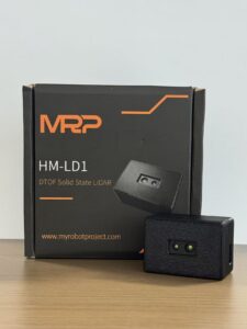
For small drones, payload weight and integration complexity are often the limiting factors. The DTOF Solid State LiDAR HM-LD1 – DTOF SSL is a compact dToF solid-state LiDAR module designed for real-time depth imaging and 3D point cloud output. With a listed weight of 28 g, low 1.2 W power consumption, and support for UART/UDP/UVC interfaces, it is suitable for UAV obstacle detection, altitude hold, terrain following, robot navigation, smart inspection, security perception, and embedded vision development.
The HM-LD1 is based on SPAD dToF technology and provides real-time depth images and 3D point cloud data for environmental perception. It supports indoor or nighttime ranging up to 25 m and outdoor daytime ranging up to 8 m, according to the provided product details. This makes it relevant for obstacle avoidance, distance detection, autonomous navigation, smart inspection, and robotic vision development. Its interface options allow integration with PCs, Raspberry Pi, flight controllers, and embedded platforms.
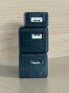
The product information also emphasizes multi-scenario applications for drones, robots, cameras, and security systems. For UAVs, the module can enable altitude hold, terrain following, obstacle detection, and local spatial awareness. For robotics, it can assist navigation, obstacle avoidance, and SLAM-related experimentation. It may also support autofocus, user presence detection, object recognition, volume measurement, and zone intrusion monitoring depending on system design.
Here’s the practical view: the HM-LD1 is not positioned as a heavy survey payload. It is a lightweight embedded perception module for systems that need depth data without adding much payload burden. That makes it a strong candidate for small UAV development, compact robot perception, industrial inspection tools, and embedded depth-sensing experiments where size, power, interface flexibility, and software support matter.
HM-LD1 dToF Solid-State LiDAR Specifications
| Specification | HM-LD1 Value |
|---|---|
| Product Name | DTOF Solid State LiDAR HM-LD1 – DTOF SSL |
| Dimension | 43.5 mm × 30 mm × 26.5 mm |
| Ranging Capability | Indoor: 0.5–25 m; Outdoor: 0.2–8 m |
| Ranging Accuracy | ±3 cm |
| Field of View | 60° horizontal × 45° vertical |
| Weight | 28 g |
| Resolution | 40 × 30 |
| Frame Rate | 10 fps |
| Interface | UART / UDP / UVC |
| Operating Temperature | -20 ℃ to 60 ℃ |
| Power Consumption | 1.2 W |
| SDK Support | x86 Windows, x86 Linux, ARM Linux |
View Product Details & Pricing ➔
Why These Specs Matter for Drones
Weight: 28 g. A 28 g LiDAR module is practical for compact UAV platforms where payload affects flight time, stability, and motor efficiency. This makes the module relevant for small drone obstacle sensing, inspection, and experimental autonomy projects where larger scanning systems are too heavy.
Power consumption: 1.2 W. A 1.2 W load is manageable for many embedded UAV power systems, but integrators still need clean regulated power and must account for total system current draw. Motors, radios, processors, cameras, and sensors all compete for battery energy.
Field of view: 60° × 45°. This FOV is suitable for directional perception. Forward-facing mounting can support obstacle awareness. Downward mounting can support altitude or terrain sensing. Multi-sensor configurations can expand coverage when a single module does not cover all required directions.
Range: indoor 0.5–25 m, outdoor 0.2–8 m. Outdoor sunlight reduces usable range compared with indoor or nighttime operation. For navigation and obstacle avoidance, integrators must match maximum speed, braking distance, and control latency to reliable outdoor detection range.
Output: depth map and point cloud. Depth maps are useful for obstacle zones and embedded perception, while point cloud data can support spatial understanding, robotics development, local mapping, or SLAM-related experimentation. The 40 × 30 resolution and 10 fps frame rate should be evaluated against the drone’s speed and mission requirements.
Need a compact LiDAR module for drone obstacle detection, altitude hold, terrain following, or embedded 3D perception? View the HM-LD1 dToF solid-state LiDAR specifications and download the product brochure at DTOF SSL HM-LD1 Product Brochure.
Drone LiDAR Selection Checklist
- ✅ Mission: Mapping, navigation, obstacle avoidance, inspection, terrain following, or landing assistance?
- ✅ Payload limit: Can the drone carry the sensor, mount, processor, cables, regulator, and safety margin?
- ✅ Range: Is the reliable outdoor range enough for the drone’s speed, braking distance, and operating environment?
- ✅ Accuracy: Does the application need centimeter-level distance readings or general obstacle zones?
- ✅ Field of view: Is the FOV wide enough for forward, downward, or side sensing without leaving critical blind spots?
- ✅ Frame rate: Can the update rate support real-time control after processing and flight-controller latency?
- ✅ Power: Can the UAV supply stable voltage and current without excessive battery drain or electrical noise?
- ✅ Interface: Does the sensor support UART, UDP, UVC, or the required development interface?
- ✅ SDK: Are Windows, Linux, ARM Linux, Raspberry Pi, or Jetson workflows supported?
- ✅ Environment: Will the sensor operate in sunlight, dust, vibration, mist, airflow, and temperature extremes?
- ✅ Software: Can your stack consume depth maps, point clouds, distance data, or obstacle-zone outputs?
- ✅ Support: Is technical documentation and integration support available when the real-world issues show up?
For teams developing UAVs, robots, or inspection platforms, supplier support can be as important as the sensor itself. MRP specializes in perception and positioning modules for robots and UAVs, with an independent R&D team focused on perception and positioning technology. The product information highlights technical support for integration and application, source-factory manufacturing, stable supply, and customized OEM/ODM options. Developers can also access account-related resources through the MRP user portal.
Look, no checklist replaces field testing. But a disciplined selection process keeps the project from drifting. Start with the mission, then work through payload, power, range, field of view, data output, software support, and environmental limits. If those items line up, integration becomes much more predictable.
Common Mistakes When Using LiDAR from Drone Platforms
Assuming Maximum Range Applies in All Conditions
Maximum range is not guaranteed in every environment. Outdoor sunlight, low-reflectivity targets, angled surfaces, rain, dust, mist, and vibration can reduce effective range. Engineers should design around validated reliable detection distance, not only the highest number in a product table.
In the shop, we call this designing for the real day, not the brochure day. If the drone will fly in bright sunlight near concrete, steel, water, dirt, vegetation, or dark painted equipment, test those targets before finalizing your control logic.
Choosing a Sensor Based Only on Distance
Range is important, but it is not the only specification. Weight, field of view, frame rate, resolution, power consumption, interface, SDK support, and mechanical integration can matter more for UAV success. A long-range sensor that is too heavy, power-hungry, or difficult to integrate may not be suitable for a small drone.
It is common to over-focus on the biggest range number. For small UAVs, a practical sensor is the one the aircraft can carry, power, cool, communicate with, and process in real time. A balanced set of specifications usually beats one impressive number.
Ignoring Drone Speed and Braking Distance
A drone moving too quickly may not react in time if reliable obstacle detection range is short. The avoidance system must account for sensor frame rate, processing latency, flight controller response, braking distance, and safety margin. This is especially important outdoors where compact LiDAR range may be lower than indoor range.
Here’s the deal: obstacle detection is not just sensing. It is sensing plus decision plus control response. If those three pieces do not fit inside the available distance and time, the drone may still hit the obstacle even though the LiDAR saw it.
Mounting the Sensor Without Considering Blind Zones
Propellers, arms, landing gear, brackets, and cables can block the field of view. A sensor must be mounted so that its optical path is clear and its field of view matches the mission. Testing should be performed with the complete drone assembly, not only with the sensor on a bench.
A clean field of view on the CAD model is not enough. Check the real aircraft with the real bracket, real wiring, real prop guards, and real landing gear. Then validate again under vibration and flight attitude changes.
Treating LiDAR as a Complete Autonomy System
LiDAR is a perception input, not a complete autonomy stack. Obstacle avoidance requires data processing, decision logic, flight control integration, fail-safe design, and extensive testing. A drone must know what to do with the LiDAR data before that data can improve safety.
The sensor reports distance. The system has to decide whether that distance is safe, whether the obstacle is relevant, how fast the drone is moving, and what corrective action is allowed. Without that logic, even good depth data is just data.
Forgetting Calibration and Timestamping
Depth data must be aligned with the drone coordinate frame, IMU readings, camera data, and flight controller timing. Without calibration and timestamping, the drone may interpret correct measurements incorrectly. This can lead to unstable behavior, wrong obstacle position estimates, or poor sensor fusion performance.
Calibration work may feel tedious, but it is the backbone of trustworthy perception. If the LiDAR, camera, IMU, and flight controller disagree about time or orientation, the autonomy stack is working from a bad picture of the world.
Frequently Asked Questions About LiDAR from Drone Systems
Is there any LiDAR for small drones?
What should beginners consider before buying a LiDAR drone setup?
What is the difference between drone LiDAR and drone photogrammetry?
Can LiDAR from a drone be used for obstacle avoidance?
How far can a drone LiDAR sensor detect objects?
Is solid-state LiDAR better for drones?
What interface is best for integrating LiDAR with a drone?
Can a lightweight LiDAR sensor be used for drone mapping?
What field of view is good for drone obstacle avoidance?
Does drone LiDAR work outdoors in sunlight?
If you are developing a UAV, robot, or inspection platform and need help selecting a lightweight LiDAR sensor, contact the MRP team for integration guidance, SDK support, and OEM/ODM customization options. You can review the HM-LD1 product page, download the brochure, or log in through the MRP account portal for support-related resources.
📚 References & Further Reading
- ✅ Industry Standard: Time of flight measurement overview and STMicroelectronics embedded sensing ecosystem
- ✅ Related Guide: Drone obstacle avoidance solutions and build VIO and VSLAM systems