Drones with LiDAR Camera: Lightweight Sensor Options for UAV Mapping, Surveying, and Obstacle Avoidance
Traditional airborne LiDAR systems can deliver excellent 3D perception, but here’s the deal: a lot of them were never built with small UAVs in mind. They can be too heavy, too power-hungry, too expensive, or too awkward to mount on compact drone platforms. For many engineering teams, the real challenge is not finding any LiDAR sensor. It is finding a LiDAR camera that fits the aircraft’s payload budget, power envelope, interface stack, and mission profile without cutting flight time in half or throwing off the airframe balance. That is why drones used for bridge inspection, terrain following, obstacle avoidance, short-range mapping, and robotic vision development increasingly rely on compact solid-state depth sensors instead of bulky scanning payloads.
For engineers evaluating drones with LiDAR camera modules, the most important question is not just “How far can it see?” Look, range matters, but range on a brochure is only one piece of the job. The better question is whether the sensor can produce stable depth data under real UAV operating conditions: vibration, sunlight, prop wash, fast attitude changes, limited onboard compute, and tight power budgets. This guide explains how LiDAR camera systems work, which specifications matter most, how they differ from RGB and stereo cameras, and where a compact dToF module such as the DTOF Solid State LiDAR HM-LD1 fits into lightweight drone integration workflows.
Table of Contents
- 👉 What Are Drones with LiDAR Camera?
- 👉 Why LiDAR Matters for UAV Mapping, Surveying, and Obstacle Avoidance
- 👉 How a LiDAR Camera Works on a Drone
- 👉 Key Specifications to Compare Before Choosing a UAV LiDAR Camera
- 👉 Lightweight Product Option: DTOF Solid State LiDAR HM-LD1
- 👉 Using LiDAR Cameras for UAV Mapping and Surveying
- 👉 Using LiDAR Cameras for Obstacle Avoidance and Navigation
- 👉 Integration Workflow for Drone LiDAR Camera Systems
- 👉 How to Choose the Right LiDAR Camera for Your Drone
- 👉 Common Mistakes When Selecting UAV LiDAR Sensors
- 👉 FAQ: Drones with LiDAR Camera
What Are Drones with LiDAR Camera?
The phrase drones with LiDAR camera can mean a few different things, and that distinction matters when you are buying hardware or designing a UAV platform. In some projects, it refers to a complete drone that ships with a LiDAR payload already installed. In others, it means a UAV that has a mounting and power architecture ready for a LiDAR module, but the sensor is selected later by the integrator. In industrial robotics, it often refers to a compact depth-sensing module that streams distance data to a companion computer, flight controller, or embedded Linux board.
A LiDAR camera is not the same thing as a normal RGB camera. RGB cameras capture color and texture, which are useful for visual inspection, photogrammetry, and object recognition. LiDAR cameras measure distance. They create depth maps, 3D point clouds, or structured range outputs that represent how far objects are from the sensor. In UAV systems, that difference is critical because obstacle avoidance, altitude hold, terrain following, and autonomous navigation depend on accurate geometry rather than color information alone.
LiDAR Camera vs RGB Camera vs Depth Camera
RGB cameras are excellent for visual detail, but they depend heavily on light, contrast, and surface texture. In the shop, that means a camera can look great under controlled lighting and then struggle when pointed at a plain wall, a shiny pipe, a dark floor, or a sunlit concrete deck. Stereo depth cameras estimate distance from the disparity between two images, so they need enough scene texture and a stable baseline. Time-of-flight depth cameras measure the travel time of emitted light, which allows them to infer distance more directly. LiDAR modules go one step further in many industrial implementations by producing geometric measurements that are better suited to navigation, obstacle detection, and 3D perception. Solid-state dToF LiDAR modules can provide depth maps and point cloud data without mechanical scanning parts, which is attractive for drones where vibration, weight, and maintenance matter.
Drone Payload vs Drone Sensor
In practice, a “LiDAR drone” often means a complete aerial mapping package with GNSS, IMU, and survey software. A “LiDAR camera for drones,” by contrast, often means a sensor module that an integrator mounts onto a UAV and connects to the rest of the autonomy stack. That difference changes the buying criteria. A large survey drone may prioritize scan density and georeferencing, while a small UAV may care more about weight, power draw, SDK support, and communication interfaces. If your project is still in prototyping mode, a compact sensor is often the more flexible path because it can be tested on multiple airframes and compute platforms before you commit to a final system design.
For a broader sensor-selection workflow, see our guide on LiDAR with drone: how to choose a lightweight sensor for UAV mapping.
Why LiDAR Matters for UAV Mapping, Surveying, and Obstacle Avoidance
LiDAR matters on UAVs because drones often operate in environments where cameras alone are not enough. Surfaces may lack texture, lighting may shift quickly, reflective materials may confuse vision algorithms, and the drone itself may need to react before a human pilot can interpret a video feed. LiDAR gives the aircraft direct distance measurements, which makes it valuable for everything from short-range obstacle detection to 3D environmental awareness and industrial asset measurement.
Here’s the practical way to think about it: an RGB image tells you what something looks like, while LiDAR helps tell you where it is. That spatial information is what a drone needs when it is trying to hold altitude over uneven ground, approach a wall without hitting it, inspect a bridge beam from a safe offset, or fly through a tight industrial aisle. The aircraft is not making decisions based on pretty pictures. It is making decisions based on distance, direction, and timing.
In mapping and surveying, LiDAR provides a direct spatial representation of structures and terrain. That makes it useful when you need to measure the distance to a bridge deck, a utility tower, a dam face, a building facade, or a narrow industrial passage. For inspection work, LiDAR can help quantify clearances and detect geometry that may be difficult to infer from color imagery alone. For autonomous flight, LiDAR can support real-time safety behavior by defining no-go zones, near-field alert ranges, or terrain offsets that help the drone stay stable and avoid collisions.
Mapping and Surveying Advantages
When UAV teams evaluate LiDAR for mapping, they are usually looking for direct 3D measurement and reliable geometry capture. Compared with photogrammetry, LiDAR does not depend as much on surface texture or ambient brightness, which can improve consistency in low-contrast scenes. It is especially useful in infrastructure inspection, underground or indoor flight, and close-range mapping around hard-to-reach structures.
That said, survey-grade mapping still requires more than a sensor. Accurate mapping usually depends on GNSS, IMU data, synchronization, calibration, and post-processing software. A compact module can be valuable for measurement-oriented perception, but it should be matched to the mission rather than treated as a universal replacement for a full airborne survey payload. The smart move is to separate lightweight perception jobs from professional georeferenced survey jobs before buying hardware.
✅ For local inspection, LiDAR can help measure object distance and structure geometry.
✅ For indoor or low-texture scenes, LiDAR can reduce dependence on visual contrast.
✅ For short-range mapping, compact depth data can be easier to process onboard.
✅ For professional land surveying, LiDAR still needs proper positioning, calibration, and mapping workflow support.
Obstacle Avoidance Advantages
For obstacle avoidance, LiDAR’s biggest advantage is immediate spatial awareness. A drone can use a depth stream or point cloud to detect objects directly in front of, below, or around the aircraft. That makes it easier to support autonomous navigation in warehouses, industrial plants, inspection corridors, and close-quarters outdoor work. A system with a useful field of view and low latency can provide enough data for the controller to slow down, stop, or change course before a collision occurs.
For smaller UAVs, this can dramatically improve mission confidence without requiring a large payload or a heavy gimbal-mounted camera package. A lightweight LiDAR camera is not magic, and it will not fix a poorly designed control loop. But when the sensor, mounting angle, processing pipeline, and flight behavior are matched properly, it gives the drone a much better sense of nearby geometry.
For more mission examples and drone LiDAR use cases, read Drone LiDAR Guide: Best Use Cases and Specs.
How a LiDAR Camera Works on a Drone
A LiDAR camera works by emitting light, receiving the reflected signal, and calculating how far the return traveled. In direct time-of-flight systems, the sensor measures the interval between emission and return. Because the speed of light is known, the system can convert that timing into distance. On a drone, this becomes especially useful because the aircraft is always moving, so the sensor has to produce a stable and timely depth output rather than a delayed or averaged estimate that might be too slow for control decisions.
Direct time-of-flight, or dToF, is a practical approach for UAVs because it can provide real-world distance data with a relatively compact sensor architecture. The sensor emits pulses, receives the reflected photons, and calculates the range to the target. The output can be organized as a depth map, which is convenient for embedded perception, or transformed into a point cloud for visualization, mapping, and measurement. For small drones, the important point is not abstract sensor theory. It is whether the data is reliable enough to feed navigation logic, obstacle avoidance, and terrain following routines under actual flight conditions.
Direct Time-of-Flight LiDAR
For background on the physics of time-of-flight sensing, see Time of flight. In a dToF LiDAR system, the returned signal does not have to be interpreted through image disparity or color-based inference. That makes the measurement pipeline simpler in many applications. The result is distance data that can be mapped to each pixel or measurement cell. This is particularly valuable when the drone needs to detect a wall, a tree line, a landing surface, or an approaching obstacle with consistent geometry.
Look, no sensor is perfect. Reflective surfaces, absorbent dark materials, rain, dust, fog, and strong sunlight can all affect the usable return. But compared with a purely visual method, dToF gives the system a direct ranging mechanism. For UAV engineers, that direct measurement path is often easier to validate, easier to threshold, and easier to turn into safety logic.
SPAD-Based Solid-State LiDAR
HM-LD1 uses SPAD-based solid-state dToF technology. SPAD stands for single-photon avalanche diode, which is a sensing approach designed to detect very small photon returns. That makes it useful in compact time-of-flight systems that need to extract range information from limited signal levels. Solid-state architectures are attractive for drones because they avoid bulky moving parts, reduce mechanical complexity, and fit better into lightweight platforms where vibration and endurance are important. For semiconductor background on sensing and imaging components, see onsemi, which provides industry resources related to advanced sensing technologies used in industrial perception systems.
In the shop, fewer moving parts usually means fewer mechanical headaches. That does not mean installation is automatic. You still need to pay attention to vibration, heat, alignment, power stability, and data handling. But a solid-state LiDAR module gives the mechanical team a better starting point than a heavy spinning scanner when the airframe is small and every gram matters.
Depth Map vs Point Cloud
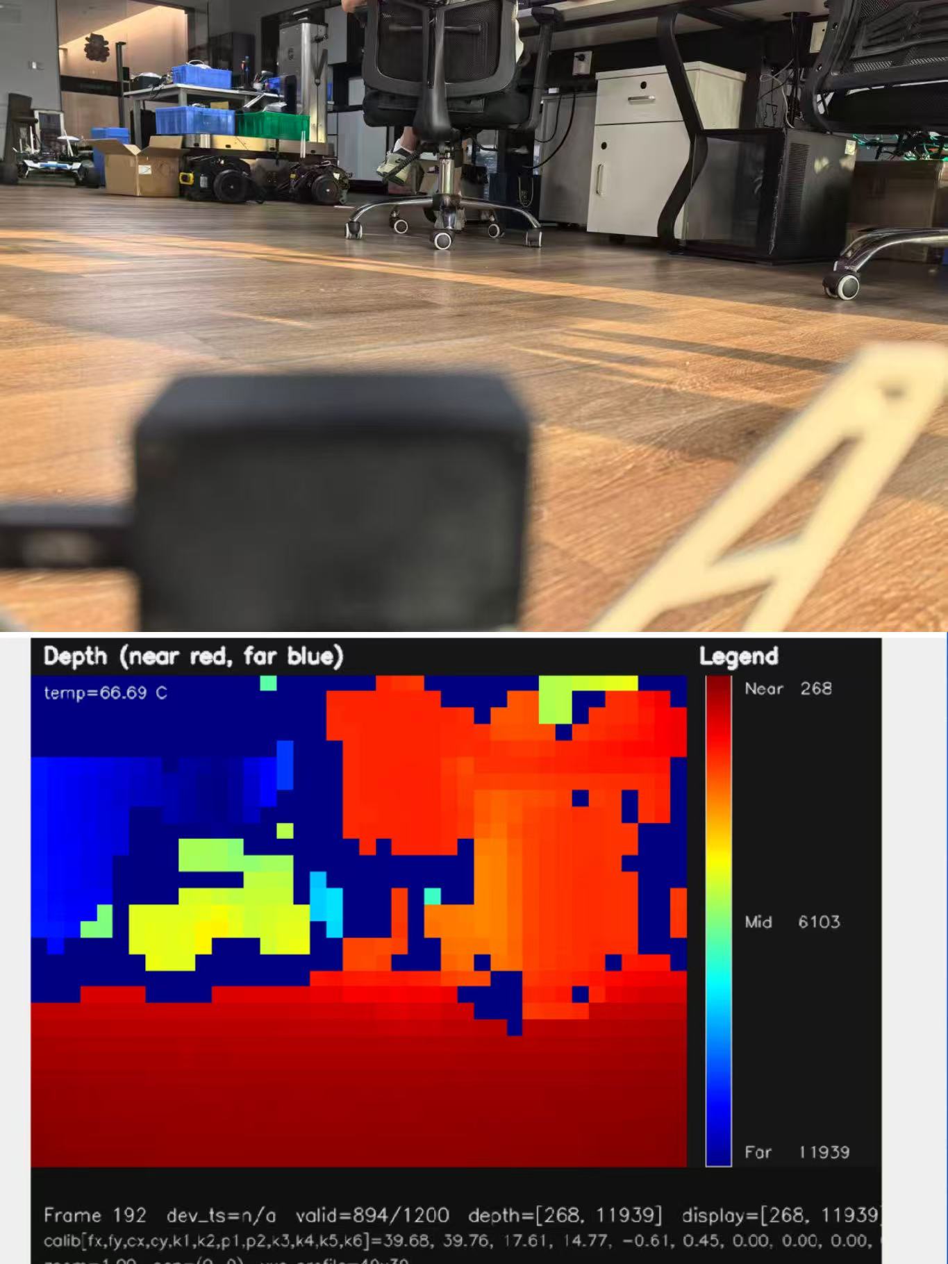
A depth map is usually the easiest data form for onboard obstacle avoidance. Each pixel or cell stores a distance value, so the system can quickly identify near, mid, and far regions. A point cloud is a 3D representation in which each measurement becomes an X, Y, Z coordinate. Point clouds are more powerful for mapping, inspection, and spatial analysis, but they usually require more processing. On a drone, both outputs can be useful. Depth maps are ideal for fast reaction, while point clouds are useful for visualization, logging, and post-flight analysis.
✅ Use a depth map when you need fast detection zones, altitude checks, or simple near-object warnings.
✅ Use a point cloud when you need 3D visualization, mapping, object geometry, or inspection records.
✅ Use both when the drone needs real-time behavior during flight and useful spatial data after the mission.
Why Field of View Matters on UAVs
Field of view controls how much of the scene the LiDAR camera can observe at once. On a drone, that affects both safety and mission utility. A wide horizontal FOV helps the aircraft detect obstacles off-axis, while vertical coverage helps with altitude hold, landing, and terrain changes. For downward sensing, vertical coverage can be just as important as horizontal coverage because the drone may need to monitor the surface below it during takeoff, descent, or low-altitude inspection. The key is to match FOV to the flight pattern and control strategy rather than assume wider is always better.
A narrow FOV may give a clean look straight ahead but miss side hazards. A very wide FOV may capture more context but require smarter filtering and mounting decisions. For UAVs, FOV should always be reviewed together with airspeed, stopping distance, frame rate, and expected obstacle size. The right coverage is the one that gives the controller enough time and geometry to make a safe decision.
Key Specifications to Compare Before Choosing a UAV LiDAR Camera
When choosing a LiDAR camera for a drone, it is tempting to focus on a single headline specification such as maximum range. In reality, UAV integration is a multi-variable engineering problem. The sensor must fit the payload envelope, support the mission geometry, communicate cleanly with the compute stack, and perform under the lighting and motion conditions of the actual flight. The following specifications are usually the most important for B2B buyers and integrators.
Weight and Payload Budget
Every gram matters on a UAV. Even small payload changes can affect flight time, climb performance, motor temperature, and center of gravity. A 28 g LiDAR module is appealing for compact aircraft because it is easier to mount without redesigning the entire platform. Lower payload mass also gives integrators more room for batteries, companion computers, or stabilization hardware. In drone projects, weight should always be evaluated alongside cable mass, mounting brackets, vibration isolation, and any regulator or interface board required to power the sensor.
Here’s the deal: payload does not end at the sensor housing. Once you add brackets, screws, cables, connectors, strain relief, a voltage regulator, and maybe a small processor, your “28 g sensor” has become a subsystem. Good drone teams calculate the full installed mass before they promise flight time or publish a design target.
Ranging Capability: Indoor vs Outdoor
LiDAR range is not a fixed number in every environment. It depends on lighting, reflectivity, target material, optics, and processing. That is why buyers should compare indoor and outdoor performance separately. For HM-LD1, the provided specifications indicate indoor ranging from 0.5 to 25 m and outdoor ranging from 0.2 to 8 m. The product details also note that it can measure even at long distances outdoors on a clear summer day, assuming about 80,000 lux, which is useful context for real-world sunlight evaluation. If your mission involves outdoor flight, always test under expected daylight, surface types, and approach angles.
Outdoor range is where many teams get surprised. A sensor that looks excellent in a lab can behave differently against asphalt at noon, white concrete in glare, dark vegetation, wet metal, or a shaded bridge column. Do not make the purchasing decision from a maximum-range number alone. Put sample targets in the same kind of environment your drone will actually fly in.
Ranging Accuracy
Accuracy affects whether the drone can use LiDAR only for presence detection or also for more precise measurement tasks. HM-LD1 lists a ranging accuracy of ±3 cm, which is strong enough for many short-range detection, navigation, and inspection workflows. That level of accuracy can support obstacle avoidance, landing aid, and relative distance measurement, but total system accuracy also depends on vibration, mounting angle, calibration, and the quality of the control loop. In airborne applications, the sensor is only one part of the accuracy chain.
If the sensor is mounted at a poor angle, if the drone frame flexes, or if the time alignment between LiDAR and pose data is sloppy, the final measurement can drift even when the sensor itself is performing well. For mapping and inspection, treat accuracy as a system-level result, not a single line in the datasheet.
Resolution
Resolution describes how dense the depth output is. The HM-LD1 provides 40 × 30 resolution, which is compact enough for embedded processing while still being useful for real-time depth perception. Higher resolution usually gives more spatial detail, but it also increases data load and can raise compute demands. For small UAVs, the right balance is often a depth stream that is dense enough to detect obstacles and estimate distances, but not so heavy that it burdens the flight computer or slows reaction time.
For obstacle detection, you may not need a massive point cloud. You need enough spatial cells to identify whether something is inside the flight path. For fine-detail mapping, higher density may matter more. The correct resolution depends on the size of the obstacle, the distance to the target, the drone speed, and the decision logic that consumes the data.
Frame Rate
HM-LD1 operates at 10 fps. In practical drone terms, frame rate determines how often the controller receives updated distance information. Ten frames per second can be suitable for many controlled-speed operations, including hover assistance, low-speed inspection, and short-range obstacle awareness. However, if a drone is flying quickly or in a cluttered environment, frame rate must be considered together with latency and stopping distance. A fast aircraft needs enough update rate to react before the next obstacle arrives.
Frame rate by itself is not the whole story either. You also need to know how long it takes to capture, transmit, process, filter, and act on the data. A clean 10 fps stream with predictable latency can be more useful than a faster stream with unstable timing. For flight control, consistency matters.
Field of View
The HM-LD1 field of view is 60° horizontal by 45° vertical. That is a practical coverage window for forward sensing, angled mounting, and some downward or oblique monitoring strategies. On drones, FOV is often more important than users expect because it determines what the sensor sees before the aircraft reaches the obstacle. For altitude hold, a downward-facing mount can be useful. For front-facing detection, the horizontal spread matters more. The best FOV is therefore mission-dependent.
For example, a forward-facing drone inspecting a corridor may need horizontal coverage to catch wall edges and protrusions. A drone flying close to a roofline may need angled coverage. A terrain-following drone may need downward coverage and clean ground returns. Before selecting a sensor, sketch the flight path and decide what geometry must be visible at each stage of the mission.
Interface Compatibility
The module supports UART, UDP, and UVC interfaces. That is valuable because drone development stacks vary widely. UART can be useful for embedded communication and simple integration paths. UDP can work well when data needs to move across a networked system or companion computer. UVC is convenient for hosts that handle camera-like streams. If a sensor cannot speak the language of your controller or computer, even excellent range specs will not save the project. Interface compatibility often saves more integration time than any other feature.
✅ UART is useful when the integration path needs simple structured data or embedded controller communication.
✅ UDP is useful when depth or point cloud data needs to move across an onboard network.
✅ UVC is useful when the host platform can handle the sensor like a camera-style streaming device.
SDK and Development Platform Support
MRP offers SDK support for x86 Windows, x86 Linux, and ARM Linux. That matters because UAV development rarely happens on one machine type only. Engineering teams often prototype on a desktop PC, validate on Linux, and then move to ARM-based companion computers or embedded boards. SDK availability reduces integration risk, shortens development time, and makes it easier to test perception logic before flight testing. If you are designing a reusable platform, broad SDK support is usually a major advantage.
In the shop, documentation and sample code can be worth as much as hardware performance. A sensor with a clean SDK, clear data formats, and responsive technical support can save weeks of integration time. A sensor with poor software support can turn a simple prototype into a long debugging job.
Power Consumption
The HM-LD1 power consumption is 1.2 W, which is low enough to be attractive for lightweight UAVs. Power draw affects battery life, heat generation, and regulator sizing. A low-power sensor does not just extend endurance. It also reduces thermal management complexity and leaves more energy available for propulsion and onboard computing. For small drones, low power consumption can be just as important as accuracy because it determines whether the aircraft can complete the mission at all.
Power stability is also important. UAV systems can be noisy electrically, especially around motors, ESCs, transmitters, and switching regulators. A low-power sensor still needs clean power, proper grounding, and cabling that does not introduce intermittent resets or dropped frames.
Operating Temperature
The operating temperature range is -20 ℃ to 60 ℃. For industrial UAVs, that range matters because drones are often deployed outdoors in hot sun, cold mornings, wind, or seasonal weather changes. Sensors that perform well in the lab but fail in the field are not suitable for industrial deployment. If your mission includes seasonal inspection, warehouse operations, or outdoor perimeter patrols, temperature tolerance should be treated as a primary requirement rather than an afterthought.
Lightweight Product Option: DTOF Solid State LiDAR HM-LD1
The DTOF Solid State LiDAR HM-LD1 is a compact SPAD dToF solid-state LiDAR module designed for real-time depth images and 3D point cloud data. It is well suited to UAV altitude hold, terrain following, obstacle avoidance, robotic navigation, smart inspection, distance detection, and embedded vision development. Because it supports UVC, UDP, and UART interfaces, it can be integrated with PCs, Raspberry Pi systems, flight controllers, and embedded platforms during both prototyping and deployment.
Beyond the sensor hardware itself, the platform is positioned for practical engineering use. It is supported by SDKs for x86 Windows, x86 Linux, and ARM Linux, which gives developers multiple paths for evaluation and integration. The supplier also emphasizes independent R&D, professional technical support, source-factory manufacturing, and customization services for OEM and ODM needs. For teams building UAV and robotics products, that kind of support can reduce integration risk and accelerate time to test.

| Dimension | 43.5mm*30mm*26.5mm |
| Ranging Capability | Indoor: 0.5-25m; Outdoor: 0.2-8m |
| Ranging Accuracy | ±3cm |
| FOV | 60°(H) x45°(V) |
| Weight | 28g |
| Resolution | 40*30 |
| Frame Rate | 10fps |
| Interface | UART/UDP/UVC |
| Operating Temperature | -20 ℃ – 60 ℃ |
| Power Consumption | 1.2 W |
The point cloud and depth map output provide an example of ranging measurement data displayed as point cloud and depth data. For drones, that means the module can support both low-level control logic and higher-level perception workflows depending on how the system is architected. In a compact UAV, a depth map may be enough for obstacle avoidance. In a more advanced system, the same data can be transformed into point clouds for logging, inspection, or spatial analysis.
One of the module’s strongest application points is long-distance short-range perception in difficult-to-access environments. The product details note that it can measure accurately even from 8 meters outdoors under clear summer daylight conditions, assuming 80,000 lux. That makes it useful for objects such as bridges, expressways, and dams, where safe close access can be difficult. For UAV teams, that kind of capability is especially relevant in infrastructure inspection and terrain monitoring.
Its compact and lightweight form factor also simplifies integration. A small housing is easier to fit onto autonomous mobile robots, inspection drones, and embedded systems where space is limited. When weight affects flight distance, a 28 g module can make the difference between a practical UAV design and a system that is too heavy to stay airborne for a useful mission duration. For a drone platform, this is not a minor detail; it is often a deciding factor.
✅ Good fit for compact UAVs that need lightweight depth sensing.
✅ Useful for close-range inspection, obstacle detection, and development work.
✅ Interface options help teams test on PCs, Raspberry Pi systems, embedded Linux boards, and flight-control hardware.
✅ Low power draw helps protect flight endurance and thermal margin.
Download the product brochure: DTOF SSL HM-LD1 Product Brochure
View Product Details & Pricing ➔
Using LiDAR Cameras for UAV Mapping and Surveying
Lightweight LiDAR cameras are especially useful when the mapping problem is local, constrained, or inspection-oriented rather than large-area survey-grade. If a drone must measure a building facade, scan an indoor corridor, inspect a bridge edge, or estimate clearances near industrial assets, a compact depth sensor can be extremely effective. The advantage is not just 3D data; it is getting 3D data from a system that still flies safely and economically.
In these scenarios, the most important benefit is measurement consistency. LiDAR can capture geometry even when visual texture is poor or when lighting changes from one part of the flight path to another. That makes it attractive for warehouses, tunnels, utility spaces, and infrastructure where RGB-only solutions may struggle. For short-range mapping, the drone does not need a massive survey payload to create useful outputs. It needs a reliable depth source and a workflow that converts that depth into actionable spatial information.
When Lightweight LiDAR Is Useful for Mapping
Lightweight LiDAR is useful when the map target is close, the flight path is constrained, or the drone has limited payload capacity. It can be used for indoor UAV mapping, confined-space scanning, low-altitude inspection, bridge clearance checks, and industrial asset measurement. It is also useful in R&D environments where teams need a sensor that can be moved between test drones quickly. For development, this flexibility is often more valuable than ultra-high density. Teams can verify calibration, test data fusion, and validate control behavior before investing in a heavier survey payload.
Look, if the job is to inspect a bridge joint, estimate distance to a wall, or map a small indoor zone, you may not need a full airborne survey rig. You need dependable close-range depth, clean integration, and a way to turn sensor output into useful measurements. That is where compact LiDAR cameras earn their keep.
Survey-Grade Mapping Requirements
Survey-grade airborne mapping is a different category of work. It typically requires higher scan density, precise GNSS correction, IMU integration, timestamp synchronization, and post-processing software for point cloud alignment and quality control. Those requirements matter because a map is only as trustworthy as the coordinate system behind it. A compact dToF module like HM-LD1 is better positioned for lightweight perception, short-range mapping, and inspection than for replacing a professional long-range airborne survey scanner. The key is to match the sensor to the mission, not to overspecify or underspecify the payload.
✅ Use lightweight LiDAR for local geometry, close-range inspection, and embedded perception.
✅ Use survey-grade airborne LiDAR when you need professional georeferenced maps over larger areas.
✅ Use GNSS, IMU, time synchronization, and calibration when measurement output must be tied to real-world coordinates.
Point Cloud Workflow
A practical UAV point cloud workflow begins with capturing depth data, then converting that data into 3D coordinates. After that, the data is calibrated to the drone frame, fused with pose information, filtered for noise, and finally exported or visualized. This pipeline is central to drone robotics because the raw sensor output is not usually the final product. What matters is whether the data can be turned into a map, an obstacle model, or a measured object boundary quickly enough to support the mission.
⚙️ Capture stable depth data from the LiDAR camera.
⚙️ Convert depth values into 3D coordinates using the sensor model.
⚙️ Align the LiDAR frame with the UAV body frame.
⚙️ Fuse data with pose information when mapping or navigation requires it.
⚙️ Filter noise, remove outliers, and export the final data for analysis or control.
For related robotics perception work, see SLAM at CHINASI 2025.
Using LiDAR Cameras for Obstacle Avoidance and Navigation
Obstacle avoidance is one of the clearest reasons to put a LiDAR camera on a drone. Unlike visual-only systems, LiDAR can provide direct distance measurements that support immediate control responses. That means the drone can detect a wall, pole, branch, or structural edge before the aircraft reaches it, then trigger slowing, rerouting, braking, or a pilot warning. For industrial UAVs, this can make operations more predictable and safer.
In many applications, the sensor is mounted forward-facing so the flight controller can monitor the approach path. In others, it is mounted downward or at an angle so the aircraft can estimate altitude or terrain variation. The best mounting choice depends on flight direction, speed, and whether the drone is flying autonomously or under pilot supervision. A depth camera with a useful field of view and stable output can give the control logic enough information to act before the mission becomes unsafe.
Forward Obstacle Detection
Forward obstacle detection is usually the first autonomy feature teams build. A LiDAR camera can define distance zones directly in front of the aircraft and help the software decide whether to continue, slow down, or stop. This is especially valuable in warehouse aisles, industrial corridors, inspection routes, and urban environments where the drone may encounter poles, wires, or structural protrusions. The key engineering challenge is not just sensing distance, but processing the data quickly enough for the aircraft’s speed and stopping distance.
Here’s the practical question: if an obstacle appears at the edge of the useful range, can the drone slow down or stop before contact? That depends on airspeed, braking behavior, controller latency, frame rate, FOV, and how conservative the detection thresholds are. A LiDAR camera gives the data, but the flight stack has to use it properly.
Downward Altitude Hold and Terrain Following
A downward or angled LiDAR camera can improve altitude hold and terrain following because it measures the distance to the surface below the drone. This is useful when GPS is unreliable, when the ground changes height, or when the drone must stay at a stable offset from the terrain or structure. For outdoor use, teams must test how sunlight, ground reflectivity, and motion affect the readings. A sensor with enough outdoor range and a stable frame rate can significantly improve low-altitude flight reliability.
Downward sensing is especially useful in takeoff, landing, low-altitude inspection, and flights over uneven surfaces. But placement matters. If landing gear, cables, or propeller wash interfere with the sensor’s view, the data may become inconsistent. A clean mechanical installation is just as important as the sensor specification.
Zone Intrusion and Safety Monitoring
LiDAR depth maps can also define virtual zones. If an object enters a specified range, the system can trigger an alarm or control action. That makes LiDAR useful not only for UAV navigation but also for docking stations, inspection robots, and security systems. For drones, zone intrusion logic can be used to protect the airframe during landing, launch, or close-proximity inspection around infrastructure. It is a simple but powerful way to convert raw distance data into safety logic.
✅ Near zone: slow, stop, or warn the pilot.
✅ Mid zone: reduce speed or change approach angle.
✅ Far zone: monitor geometry and prepare the control system for possible action.
SLAM and Autonomous Navigation
LiDAR is often part of a SLAM stack because it provides spatial structure that supports localization and mapping. In a UAV, a compact depth sensor may be enough for local obstacle awareness, while more advanced SLAM workflows may require denser data and additional sensors. The final result depends on the mission, not only the LiDAR itself. For autonomous navigation, the sensor should be paired with stable pose estimation, appropriate filtering, and fail-safe logic so the aircraft can react predictably in complex spaces.
In real systems, LiDAR may be combined with IMU data, RGB cameras, optical flow, barometers, GNSS, or wheel-free odometry algorithms depending on the vehicle and environment. No single sensor owns the whole autonomy stack. LiDAR is one strong source of geometry, and the rest of the system has to make that geometry useful.
Integration Workflow for Drone LiDAR Camera Systems
Good drone integration is a systems engineering exercise, not just a sensor installation task. The LiDAR camera must be matched to the mission, mounted securely, powered safely, connected to the right processor, and validated under real flight conditions. A module can look excellent on paper and still fail on a UAV if vibration, sunlight, latency, or cabling were not considered.
Step 1 — Define the Mission
⚙️ Start by defining whether the drone flies indoors or outdoors, whether the mission is mapping, inspection, obstacle avoidance, or altitude hold, and how fast the aircraft will move. Also identify the minimum detection distance and whether the aircraft is autonomous or pilot-assisted. These questions determine whether you need short-range depth perception, broad obstacle coverage, or a sensor that can support a more complex mapping workflow.
Do not skip this step. In the shop, vague mission statements lead to expensive redesigns. “We need LiDAR” is not a requirement. “We need forward obstacle detection from 0.5 to 8 meters on a slow inspection UAV in outdoor daylight” is much closer to something an engineer can design around.
Step 2 — Check Payload and Mounting
⚙️ Payload is more than mass. You must also consider mounting rigidity, vibration isolation, sensor angle, cable routing, exposure to dust and propeller wash, and center-of-gravity shift. A sensor that is easy to mount but poorly aligned can produce inferior data. On drones, even a lightweight module should be mounted in a way that preserves the intended field of view and keeps the aircraft stable.
Check the installed position before cutting brackets or printing mounts. Confirm that landing gear, propellers, wires, and frame members do not block the sensor. Also confirm that the sensor will not shift under vibration. A loose sensor mount can turn good depth data into noisy, inconsistent readings.
Step 3 — Select the Interface
⚙️ Choose an interface that fits your computing architecture. UART is practical for embedded systems and simple controller communication. UDP works well when data is streamed across a network to a companion computer or processor. UVC is convenient when the host treats the sensor more like a standard camera input. The best interface is the one that minimizes friction between the sensor and your flight stack.
Before finalizing the design, confirm bandwidth, driver support, packet format, timestamp handling, and behavior after power cycling. A system that works only after manual reconnects is not ready for field operations.
Step 4 — Connect to the Compute Platform
⚙️ HM-LD1 is designed for integration with PCs, Raspberry Pi platforms, ARM Linux boards, and flight controllers. That flexibility is important because development often begins on a desktop and ends on an airborne embedded system. The broader the platform support, the easier it is to prototype, debug, and deploy. For engineering teams, this can shorten the time from sensor evaluation to field test.
When moving from the bench PC to the drone computer, test CPU load, memory use, USB or network reliability, and thermal behavior. Embedded platforms can behave differently from desktop machines, especially when they are mounted near batteries, regulators, and radio transmitters.
Step 5 — Validate Data Quality
⚙️ Validation should include indoor tests, outdoor sunlight tests, motion tests, reflective targets, dark surfaces, and temperature variation. Also check latency, frame drops, and measurement stability under vibration. The data must remain usable while the drone is moving, not only while the system is sitting on a bench. If the LiDAR performs well only in controlled test conditions, it is not yet ready for flight integration.
Good validation includes boring tests. Hover near a wall. Approach a known target slowly. Test over concrete, asphalt, grass, metal, and painted surfaces. Test in shade and sunlight. Test at different battery states. If a sensor resets when the motors spool up, you want to learn that on the ground, not during an inspection flight.
Step 6 — Integrate with Control Logic
⚙️ Raw distance data becomes useful only when it is converted into control decisions. Obstacle avoidance may use thresholds and filtering. Mapping may require calibration and pose fusion. Autonomy may require multiple sensors and fail-safe behavior. This is why LiDAR camera selection should always be tied to the control stack rather than evaluated as a standalone component. A good sensor makes the control system possible, but the system design determines whether it is actually effective.
If you are defining a new UAV platform, share your drone model, flight environment, and sensing goal with the engineering team so the sensor choice can be matched to obstacle avoidance, terrain following, inspection, or prototype mapping requirements.
How to Choose the Right LiDAR Camera for Your Drone
The right LiDAR camera depends on the mission category. Beginners, small-drone integrators, industrial inspectors, and survey teams are solving different problems, so they should not use the same buying criteria. A useful selection framework looks at payload, range, frame rate, field of view, interface, data type, and software compatibility together.
For Beginner UAV Developers
Begin with sensors that are easy to integrate. A lightweight module with clear SDK support, simple interfaces, and documented range behavior is much easier to bring into a new project than a complex survey payload. If you are still learning how to build a perception stack, prioritize low power, stable output, and straightforward development tools. You want a platform that helps you test ideas quickly.
✅ Prioritize easy setup over exotic specifications.
✅ Use SDK support to reduce early development friction.
✅ Test indoor and outdoor performance before committing to an airframe design.
For Small Drone Obstacle Avoidance
Small drones should prioritize weight, FOV, latency, and power draw. For this use case, a compact solid-state LiDAR that can produce a real-time depth map is often more valuable than a large, high-density scanner. The goal is not to create a perfect map. The goal is to ensure that the aircraft can see nearby hazards soon enough to avoid them. HM-LD1 fits this kind of work because it is compact, low power, and designed for embedded depth sensing.
For Industrial Inspection
Industrial inspection teams should focus on outdoor stability, accuracy, environmental adaptability, and technical support. In many cases, the drone is expected to operate repeatedly in difficult conditions, so the sensor should be robust enough to support repeatable work. Data export, mounting options, and platform compatibility also matter because inspection workflows often involve multiple software tools and post-flight review.
Look, inspection work is not a demo. The system has to work on Tuesday morning when the lighting is ugly, the operator is under time pressure, and the structure is not easy to access. That is why repeatability, support, and validation matter so much.
For Large-Area Fixed-Wing Mapping
Large-area fixed-wing mapping is a higher-end requirement. It usually calls for longer-range LiDAR, scan density, GNSS correction, IMU alignment, and professional post-processing. A compact dToF module is not the same thing as a survey payload. The right sensor in that category needs to fit the altitude, ground speed, and georeferencing workflow of the mission. For teams working on large-area cartography, survey software compatibility often matters as much as raw sensor specifications.
| Use Case | Most Important Specs | Recommended Sensor Characteristics |
| Small UAV obstacle avoidance | Weight, FOV, frame rate, latency, power | Compact solid-state LiDAR with real-time depth output and embedded interface support. |
| Altitude hold and terrain following | Outdoor range, accuracy, downward mounting, environmental stability | Low-power LiDAR with stable short-range outdoor distance measurement. |
| Infrastructure inspection | Accuracy, outdoor adaptability, point cloud output, compact size | Lightweight dToF module for close-range measurement and object-distance detection. |
| Indoor UAV navigation | Indoor range, SDK support, SLAM compatibility, latency | Depth sensor with point cloud output and Linux/embedded development support. |
| Survey-grade mapping | Range, scan density, GNSS/IMU integration, timestamping, point cloud workflow | Dedicated airborne LiDAR payload with RTK/PPK and professional post-processing support. |
Common Mistakes When Selecting UAV LiDAR Sensors
Many UAV projects fail not because the LiDAR itself was poor, but because the wrong selection criteria were used. Teams often compare sensor brochures as if all drone LiDAR products solve the same problem, which leads to mismatched expectations and avoidable redesign. The most common mistakes are easy to spot once you know what to look for.
Mistake 1 — Comparing Only Maximum Range
Maximum range is a useful number, but it is not the whole story. A module may perform well indoors or in low light and then deliver a shorter usable range outdoors in sunlight. For UAVs, daylight performance is often the more important benchmark. Always compare operating conditions, target reflectivity, and flight environment before making a decision.
Mistake 2 — Ignoring Weight and Power
A sensor that is accurate but too heavy can still fail the mission if it shortens flight time or overloads the airframe. Likewise, a power-hungry module can make regulator sizing difficult and reduce endurance. For drones, weight and wattage are not secondary details. They are core system constraints.
Mistake 3 — Assuming All LiDAR Is Survey-Grade
Compact LiDAR cameras and professional airborne survey payloads solve different problems. A small dToF module may be perfect for obstacle avoidance, short-range inspection, and prototype mapping, but it is not automatically a replacement for a high-density mapping system with RTK, IMU, and post-processing support. Matching expectations to the sensor class prevents disappointment.
Mistake 4 — Forgetting Integration Interfaces
Even a strong sensor becomes difficult to use if it cannot connect to the rest of the system. UART, UDP, and UVC support can dramatically reduce integration time, especially if the development team works across PCs, Raspberry Pi systems, and ARM Linux platforms. Interface flexibility should be part of the decision from the beginning.
Mistake 5 — Testing Only on the Bench
Bench tests are useful, but they do not reproduce real flight conditions. Vibration, acceleration, sunlight, propeller wash, temperature changes, and motion can all affect performance. UAV LiDAR selection should be validated in the air, not just on a workbench. A field test can reveal problems that never appear in a lab environment.
Mistake 6 — Ignoring Calibration
For mapping and navigation, calibration is essential. The LiDAR frame must be aligned with the drone body frame and, where applicable, the IMU, camera, or GNSS frame. Without calibration, even accurate range data can become difficult to use reliably. Good system design treats calibration as part of the product, not as an optional afterthought.
Here’s the deal: if the sensor coordinate frame is wrong, the drone may “see” an obstacle in the wrong place. That is not a sensor failure. That is a system integration failure. Confirm sensor angle, mounting offset, timestamp behavior, and coordinate transforms before trusting the output in autonomous flight.
FAQ: Drones with LiDAR Camera
I’m a beginner—what should I look for in a LiDAR camera for drones?
Is there a LiDAR option for small drones on a budget?
What is the best setup for survey-grade mapping or large-area fixed-wing missions?
Can a lightweight LiDAR camera be used for drone obstacle avoidance?
How important is LiDAR weight for drone integration?
What is the difference between a depth map and a point cloud?
Can drones with LiDAR camera systems work outdoors in strong sunlight?
Is a solid-state LiDAR better than a mechanical LiDAR for drones?
What interfaces should I look for when choosing a drone LiDAR camera?
Can a LiDAR camera be connected to a Raspberry Pi or embedded Linux platform?
📚 References & Further Reading
- Industry Standard: onsemi
- Related Guide: LiDAR with drone: how to choose a lightweight sensor for UAV mapping