


Avoid Obstacles Drone Solutions: How to Choose LiDAR Sensing for Safer UAV Navigation
Here’s the deal: a commercial UAV inspecting a bridge, rooftop, solar farm, warehouse, dam, or power infrastructure asset has to fly close enough to collect useful data, but not so close that it clips a wall, beam, cable, tree, column, pipe rack, machine guard, or uneven patch of terrain. In the shop, we call that the practical gap between “the mission plan looked fine” and “the aircraft came home in one piece.” Manual piloting alone is not always enough, especially when GNSS is weak, lighting changes fast, the pilot is busy framing a camera shot, or the flight path runs through a tight industrial space. A good avoid obstacles drone setup is not a gimmick. It is a real safety layer that helps protect the aircraft, payload, data, nearby structures, and the customer’s assets.
Drone obstacle avoidance comes down to choosing the right sensing technology and pairing it with flight-control logic that behaves predictably. Cameras can provide rich visual context. Ultrasonic sensors can help with short-range detection. Radar can work well when visibility is ugly. LiDAR can provide direct distance measurements, depth maps, and 3D point cloud data. This guide walks through how LiDAR-based obstacle avoidance works, which specifications matter for UAV integration, and how a compact solid-state dToF LiDAR such as the DTOF Solid-State LiDAR HM-LD1 can support safer drone navigation for indoor, outdoor, inspection, robotics, and research applications.
Table of Contents
- 👉 What Is an Avoid Obstacles Drone System?
- 👉 Why Obstacle Avoidance Matters for Commercial UAVs
- 👉 How Drone Obstacle Avoidance Works
- 👉 Drone Obstacle Avoidance Sensor Options
- 👉 Why LiDAR Is Useful for UAV Obstacle Avoidance
- 👉 What dToF Solid-State LiDAR Means
- 👉 Key LiDAR Specs to Compare Before Buying
- 👉 How to Integrate LiDAR into a Drone Platform
- 👉 DTOF Solid-State LiDAR HM-LD1 for Avoid Obstacles Drone Development
- 👉 Best Use Cases for LiDAR-Based Avoid Obstacles Drone Systems
- 👉 Buyer Checklist: How to Choose an Avoid Obstacles Drone Sensor
- 👉 Common Engineering Mistakes to Avoid
- 👉 FAQ: Avoid Obstacles Drone Solutions
- 👉 Next Step: Build a Safer Avoid Obstacles Drone with Compact LiDAR
What Is an Avoid Obstacles Drone System?
An avoid obstacles drone is a UAV equipped with sensing hardware, perception software, and flight-control responses that help detect nearby objects and reduce collision risk. Look, that phrase sounds simple, but in engineering terms it is a full system. A sensor reads the environment, a processor turns that data into something useful, software decides whether the object is a problem, and the flight controller responds by slowing, stopping, rerouting, climbing, descending, or warning the pilot.
Sharing a compact dToF sensor we’ve been working with for drone obstacle av…
Consumer drones often package obstacle avoidance as a built-in feature, but industrial UAVs, research aircraft, and custom inspection platforms usually need more deliberate sensor selection. A bridge inspection drone may need forward-facing depth sensing to maintain distance from concrete beams. A warehouse UAV may need multiple sensing directions to avoid racks, columns, doors, pallets, and lift trucks. A terrain-following drone may need downward range data to hold altitude over changing ground surfaces.
Obstacle Detection vs Obstacle Avoidance
Obstacle detection means the drone can sense that an object exists within a certain area. Obstacle avoidance means the aircraft can do something useful with that information. That distinction matters. A LiDAR module may provide accurate distance data, depth images, or point cloud output, but the drone still needs rules or autonomy logic to decide what happens next. If a forward-facing LiDAR detects a wall at three meters, the software may reduce forward velocity. If that wall reaches a hard stop threshold, the flight controller may command the drone to brake or hover.
The right response depends on the mission. During inspection, the best behavior may be to hold a fixed standoff distance instead of turning away. During indoor navigation, the drone may need to generate a new path around a rack or column. During manual pilot assistance, the system may only limit speed or provide an alert. That is why the sensor is only one part of the obstacle avoidance chain.
Why “Avoid Obstacles” Is a System-Level Requirement
A high-quality sensor cannot guarantee collision prevention if it is installed badly or paired with poor control logic. Engineers have to consider sensor placement, field of view, frame rate, processing latency, braking distance, flight speed, vibration, lighting, target reflectivity, surface angle, and object size. A forward-facing sensor cannot see behind the aircraft. A low frame rate may be fine for slow inspection but wrong for fast flight. A sensor mounted behind landing gear or too close to a propeller wash path may produce incomplete or unstable data.
For B2B UAV development, obstacle avoidance should be judged by measurable performance instead of sales language. Useful questions include detection range indoors and outdoors, horizontal and vertical field of view, weight, power draw, interface, SDK availability, operating system support, and how the autonomy stack handles invalid or noisy data. Those questions turn “avoid obstacles” from a vague feature into an engineering requirement.
Why Obstacle Avoidance Matters for Commercial UAVs
Obstacle avoidance matters because commercial drones usually operate near expensive assets and mission-critical payloads. A crash can damage the aircraft, break a camera or thermal payload, delay an inspection, or mark up the structure being inspected. In some sites, a collision can also create hazards for workers, vehicles, machines, or infrastructure. So yes, obstacle avoidance costs money. But one crash can cost more.
UAVs used in industrial inspection, mapping, research, and logistics often fly where GNSS is weak, unreliable, or unavailable. In these conditions, onboard perception becomes a major part of safe operation. LiDAR, vision, optical flow, IMU data, barometers, and other sensors may work together to improve situational awareness. If your project involves LiDAR-based drone inspection and navigation, you may also want to read the drone LiDAR guide for best use cases and specifications.
Inspection and Mapping Flights
Inspection drones often work around bridges, dams, highways, roofs, tanks, warehouses, solar farms, wind-related infrastructure, and industrial plants. Those sites are full of walls, trusses, pipes, beams, power lines, vents, railings, equipment, and rough surfaces. The pilot may need to fly close for high-resolution imagery, but close flight leaves less room for mistakes. A drone LiDAR sensor can provide distance awareness so the system can maintain a safer standoff distance or slow down before it gets into trouble.
Indoor and GNSS-Denied Navigation
Indoor drones cannot count on satellite positioning. Warehouses, laboratories, factories, tunnels, and large commercial buildings need onboard perception for navigation. In these environments, a compact depth sensor can support wall detection, rack detection, altitude monitoring, and movement through narrow spaces. LiDAR is useful because it measures distance directly instead of depending only on visual texture or ideal lighting.
Autonomous UAV Research and Development
University labs, robotics developers, embedded AI teams, and serious DIY drone builders often need real-time depth data for autonomy experiments. They may test obstacle avoidance algorithms, depth thresholding, occupancy grids, mapping, SLAM, or sensor fusion. A compact dToF LiDAR module that outputs depth maps or point cloud data can reduce the early prototyping burden. Instead of building every distance-estimation function from scratch, developers can focus on perception logic, flight-control integration, and real-world validation.
How Drone Obstacle Avoidance Works
A drone obstacle avoidance system usually follows a perception-to-action workflow. First, the sensor captures environmental data. Second, a processor turns raw signals into distance readings, depth images, point clouds, or object information. Third, software checks whether an object is inside a risk zone. Fourth, the flight controller receives a command or velocity limit. Finally, the drone slows, stops, changes path, holds position, or warns the operator.
Step 1: Sensing the Environment
Drone sensing may involve LiDAR, stereo cameras, monocular cameras, ultrasonic modules, radar, optical flow sensors, or sensor fusion. Each technology has tradeoffs. LiDAR directly measures distance using light return timing. Cameras provide visual context but may require more processing. Ultrasonic sensors are simple and low cost, but they are usually best for short-range tasks. Radar can be strong in dust, fog, smoke, or darkness, though spatial resolution depends on the radar design.
Step 2: Creating Depth or Distance Data
After sensing, the system has to create usable data. A single-point rangefinder may report one distance value. A depth sensor can produce a depth map, where each pixel represents distance. A 3D sensor may generate point cloud data, which gives spatial information across a field of view. For obstacle avoidance, depth maps and point clouds are valuable because software can identify the nearest object in a region, detect surfaces, and estimate whether a path is blocked.
Step 3: Defining Safety Zones
Obstacle avoidance logic often uses safety zones. A warning zone may reduce speed. A stop zone may command braking or hover. A path-planning zone may feed a navigation algorithm that picks a safer route. These zones should be designed around flight speed, braking ability, control latency, and mission environment. A slow indoor drone can use shorter thresholds than a fast outdoor UAV because it needs less distance to stop.
Step 4: Sending Commands to the Flight Controller
Once the software identifies a risk, the system must communicate with the flight controller or companion computer. Integration may involve UART, UDP, UVC, embedded Linux, Raspberry Pi, PC-based development, or other onboard processing platforms. Some systems send a simple obstacle distance or warning flag. Others send velocity limits, avoidance vectors, or richer perception data for autonomous planning.
Step 5: Testing in Real Flight Conditions
Bench testing is necessary, but it is not enough. A drone should be validated at realistic speeds, distances, lighting levels, object colors, reflectivity levels, surface angles, and vibration conditions. Outdoor testing is especially important for optical sensors because sunlight and target reflectivity can change performance. Engineers should test emergency override behavior, invalid-data handling, and recovery from edge cases before relying on obstacle avoidance in live operations.
Drone Obstacle Avoidance Sensor Options
There is no universal best sensor for every UAV obstacle detection problem. The right solution depends on mission type, environment, payload budget, computing resources, power availability, and control requirements. Many industrial systems use several sensing technologies together. Established industrial sensor manufacturers such as HOKUYO show how broad the LiDAR and sensing ecosystem has become for robotics, automation, and navigation applications.
LiDAR Sensors
LiDAR measures distance by emitting light and analyzing the return signal. Depending on the module, LiDAR may provide a single distance value, a 2D scan, a depth image, or 3D point cloud data. For UAV obstacle avoidance, LiDAR is useful because it provides direct distance measurements. That can simplify near-object awareness, altitude hold, terrain following, and inspection standoff control. Compact solid-state LiDAR modules are especially relevant for drones because weight, size, and power are limited.
Stereo Vision Cameras
Stereo vision cameras estimate depth by comparing two camera views. They can work well when the scene has enough texture and lighting. Stereo systems may provide rich perception data and can be combined with object recognition algorithms. Still, they may struggle with low-texture surfaces, glare, low light, repetitive patterns, or heavy processing loads. For some UAVs, stereo vision is excellent. For others, a direct depth sensor is simpler to integrate.
Ultrasonic Sensors
Ultrasonic sensors are common for short-range distance measurement. They are low cost and simple to implement, which makes them attractive for student projects and basic proximity detection. Their limitations include acoustic interference, angled surfaces, soft materials, and environmental noise. They also provide less spatial information than a depth map or point cloud. For drones, ultrasonic modules are often better for low-altitude assistance than full obstacle avoidance.
Radar Sensors
Radar sensors can operate in difficult visibility conditions such as dust, fog, smoke, or darkness. They can be valuable in harsh industrial environments where optical sensors may be challenged. Depending on the radar implementation, spatial resolution may be lower than LiDAR or vision, so small-obstacle detection and object localization must be checked carefully. Radar is often selected when environmental robustness matters more than dense 3D spatial detail.
Sensor Fusion
Industrial UAVs frequently use sensor fusion. A drone may combine LiDAR, cameras, IMU, GNSS, RTK, barometer, optical flow, radar, or visual navigation data. The goal is to cover the weaknesses of one sensor with the strengths of another. LiDAR may provide direct distance data, vision may support visual features and object classification, IMU data supports motion estimation, and GNSS or RTK supports global positioning outdoors.
Why LiDAR Is Useful for UAV Obstacle Avoidance
LiDAR is useful for UAV obstacle avoidance because it provides distance information directly. Instead of inferring depth from image features alone, a LiDAR module measures distance from emitted and returned light signals. This makes it valuable around bridges, walls, warehouses, tanks, corridors, roofs, docks, and other structured inspection targets. It can also support altitude hold, terrain following, near-object awareness, docking, and robotic vision development.
Direct Distance Measurement
Direct ranging is practical because many avoidance decisions depend on distance thresholds. If the nearest object is outside a warning threshold, the drone may continue normally. If it enters a warning area, the system may reduce speed. If it enters a stop zone, the drone may brake or hold position. A LiDAR obstacle avoidance drone can use measured distance as a clear input to flight-control decisions.
Depth Maps and Point Clouds
Depth maps and point clouds provide spatial information across a field of view. Instead of one distance measurement, the system can analyze many points in front of or below the drone. This helps detect surfaces, identify the closest region, and support algorithms such as depth thresholding, occupancy mapping, and path planning. To learn more about 3D depth sensing and portable perception workflows, explore the LiDAR scan guide for affordable portable 3D scanning and robot perception.
Compact LiDAR for Weight-Sensitive UAVs
UAV integration is constrained by size, weight, and power. Every gram affects flight time, mounting options, center of gravity, vibration behavior, and payload capacity. Compact solid-state LiDAR modules are attractive because they can provide depth sensing without the mass and mechanical complexity of larger scanning systems. For small UAVs, research platforms, and embedded prototypes, a compact module can make obstacle sensing practical without overwhelming the airframe.
What dToF Solid-State LiDAR Means
dToF means direct Time of Flight. In plain English, the sensor emits light, waits for the reflected signal to return, and calculates distance from the elapsed time. Because light travels extremely fast, the sensor must measure very small timing differences. SPAD-based dToF systems are designed for sensitive photon detection, which helps compact depth-sensing modules measure reflected light signals.
Direct Time-of-Flight Measurement
Direct time-of-flight measurement is conceptually straightforward. Light travels from the sensor to an object and back. If the system measures how long that round trip takes, it can convert elapsed time into distance. For drone applications, that distance data can estimate how close the aircraft is to a wall, floor, beam, vehicle, rack, or terrain surface.
Solid-State Design for UAV Integration
Solid-state LiDAR does not rely on large mechanical spinning assemblies the way traditional rotating scanners do. That can make the module more compact, lighter, and easier to mount on small robotic platforms. For drones, this matters because payload weight and mechanical complexity directly affect flight time and reliability. A solid-state module can be mounted forward, downward, or sideways depending on the sensing job.
SPAD Technology in Depth Sensing
SPAD technology supports photon-sensitive detection and is used in compact depth-sensing systems. For buyers, the important point is not just the detector technology inside the housing. What matters is the resulting system performance: range, accuracy, resolution, frame rate, power consumption, weight, interface, software support, and environmental adaptability.
Key LiDAR Specs to Compare Before Buying
Choosing a drone LiDAR sensor is an engineering tradeoff. A specification that looks impressive by itself may not solve the mission. Long range may come with too much weight. A lightweight sensor may have a limited field of view. High resolution may require more processing power. The best choice is the one that matches the drone’s speed, environment, payload budget, compute architecture, and safety logic.
Ranging Capability
Ranging capability should be evaluated indoors and outdoors. Outdoor performance can be affected by sunlight, target reflectivity, weather, and surface angle. For an avoid obstacles drone, useful range depends heavily on flight speed. A slow indoor drone may only need short-to-medium range detection. A faster outdoor UAV needs more time to detect the object, process the data, choose a response, and brake or reroute before impact.
Ranging Accuracy
Accuracy matters for close inspection, docking, altitude hold, terrain following, and narrow-space navigation. Centimeter-level ranging can help maintain a stable standoff distance from walls, beams, or surfaces. That said, accuracy should be validated in the real operating environment. A lab reading does not always represent outdoor sunlight, reflective metal, dark surfaces, vibration, or angled targets.
Field of View
Field of view defines how much area the sensor can see. A wider horizontal and vertical FOV can cover more of the drone’s path, but it may require more processing and careful interpretation. A narrow sensor might miss obstacles outside its view unless multiple modules are installed. Sensor placement and FOV should be planned together. A downward-facing sensor for altitude hold has different requirements from a forward-facing sensor for obstacle detection.
Resolution
Resolution affects depth map density. A 40 × 30 depth map provides 1,200 depth points per frame. That is not the same as a high-resolution camera image, but it can be very useful for compact perception tasks such as detecting the nearest region, monitoring safe distance, and generating lightweight point cloud data. For embedded drones, lower resolution can also reduce processing burden.
Frame Rate and Latency
Frame rate affects how often the system receives updated depth information. A 10 fps stream updates every 100 milliseconds before additional processing overhead. For low-speed inspection, controlled indoor flight, or altitude support, that may be suitable when paired with conservative flight logic. For faster flight, engineers must calculate detection distance, braking distance, software latency, and control response time.
Weight
Weight is one of the biggest UAV constraints. A heavier sensor can reduce flight time, require a larger airframe, alter center of gravity, and increase vibration sensitivity. For small drones, a compact 28 g module is much easier to integrate than a large scanner. Include the mounting bracket, cabling, protective housing, and vibration isolation in the total payload calculation.
Power Consumption
Power consumption affects battery life and thermal management. A low-power module reduces the burden on the UAV power system and can simplify integration into mobile robots or embedded platforms. Engineers should check voltage requirements, peak draw, cable length, electromagnetic noise, and whether the sensor shares power with other payload electronics.
Interface
Interface selection can determine how painful or painless integration becomes. UART can work well for simple embedded communication or microcontroller workflows. UDP can help with networked embedded systems and structured data streaming. UVC can be convenient for PC-style camera and depth workflows because many systems recognize UVC devices in a familiar way. A sensor that supports UART, UDP, and UVC gives developers flexibility across prototyping and deployment.
Operating Temperature
Operating temperature matters for outdoor inspection, field robotics, and industrial environments. UAVs may work in cold warehouses, hot rooftops, or changing weather. A sensor rated across a practical temperature range reduces integration risk, but the complete system should still be tested with airflow, enclosure design, heat from nearby electronics, and mission-specific duty cycles.
How to Integrate LiDAR into a Drone Platform
LiDAR integration is not just bolting a sensor onto a frame. It includes placement, power wiring, data communication, software parsing, perception logic, flight-controller commands, and validation. Developers should plan the integration workflow before selecting hardware. Navigation systems also sit inside a broader positioning ecosystem, where companies such as ComNav Technology represent the wider industry of positioning and UAV navigation technologies.
Choose Sensor Placement
Sensor placement depends on the task. A forward-facing LiDAR supports frontal obstacle detection. A downward-facing LiDAR supports altitude hold, landing assistance, and terrain following. Side-facing sensors help maintain distance from walls, tanks, bridges, or tunnel surfaces. Some UAVs may need multiple sensors to cover front, sides, rear, and downward directions. The design should avoid propeller obstruction, landing gear blockage, cable interference, and vibration-prone locations.
Connect to the Processing Platform
The sensor may connect to a Raspberry Pi, embedded Linux board, PC, Jetson-type development platform, microcontroller, or flight-control computer depending on the project. Developers should verify interface support, driver availability, bandwidth, connector style, and software examples. Do not assume universal autopilot compatibility unless it has been tested. For prototyping, a PC or Raspberry Pi workflow can simplify data visualization before moving to a flight-ready embedded configuration.
Convert Depth Data into Flight Logic
Depth data must be converted into actionable flight logic. Common methods include nearest-obstacle distance, depth thresholding, region-of-interest analysis, occupancy grids, velocity scaling, stop commands, and avoidance vectors. A simple system may slow forward motion when a depth value crosses a threshold. A more advanced system may evaluate multiple regions in the depth image and choose a safer direction. The logic should include invalid-data handling and conservative fallback behavior.
Use ROS, OpenCV, or Custom Code
Developers often use ROS, OpenCV, or custom code to process depth images and point clouds. ROS can support robotics message passing and visualization. OpenCV can support image processing and thresholding. Custom embedded code may be better for lightweight deployment. SDK availability matters because it reduces integration time. When discussing navigation algorithms and perception stacks, it is also useful to learn more about visual-based navigation for UAV systems.
Validate with Ground and Flight Testing
Validation should begin with bench testing and data visualization. Then test static obstacles at known distances. After that, move to slow-speed ground or tethered testing before free flight. Outdoor validation should include sunlight, target materials, reflective surfaces, dark objects, vegetation, and angled surfaces. Flight tests should include manual override procedures, emergency stop behavior, vibration evaluation, and data logging. No obstacle avoidance system should be trusted just because it worked in a controlled demo.
DTOF Solid-State LiDAR HM-LD1 for Avoid Obstacles Drone Development
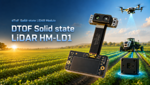
The DTOF Solid-State LiDAR HM-LD1 is a compact solid-state dToF LiDAR module based on SPAD direct Time-of-Flight technology. It is designed to deliver real-time depth images and 3D point cloud data for environmental perception. For UAV developers, it is relevant to obstacle avoidance, altitude hold, terrain following, autonomous navigation, smart inspection, robotic vision development, distance detection, and embedded prototyping.
The HM-LD1 is attractive for compact UAV integration because it weighs only 28 g and consumes 1.2 W. Those numbers matter on drones where payload capacity and battery life are always limited. It supports UART, UDP, and UVC interfaces, helping developers connect it to PCs, Raspberry Pi platforms, embedded systems, and development workflows. MRP also offers SDKs for x86 Windows, x86 Linux, and ARM Linux, which helps across different operating systems and architectures.
View Product Details & Pricing ➔
| Specification | DTOF Solid-State LiDAR HM-LD1 | Why It Matters for an Avoid Obstacles Drone |
|---|---|---|
| Dimension | 43.5 mm × 30 mm × 26.5 mm | Compact size helps integration into small UAV frames, gimbals, robot platforms, and embedded test rigs. |
| Ranging Capability | Indoor: 0.5–25 m; Outdoor: 0.2–8 m | Supports indoor navigation, nighttime ranging, and outdoor obstacle detection within the specified operating range. |
| Ranging Accuracy | ±3 cm | Centimeter-level accuracy supports close-range obstacle awareness, inspection standoff control, and terrain-related distance measurement. |
| Field of View | 60° horizontal × 45° vertical | Provides a practical forward-looking or downward-looking sensing area for compact UAV perception. |
| Weight | 28 g | Low mass helps preserve drone flight time and reduces payload burden. |
| Resolution | 40 × 30 | Provides depth image data for obstacle detection, depth thresholding, and point cloud generation. |
| Frame Rate | 10 fps | Delivers real-time depth updates suitable for low-speed and controlled navigation applications when paired with appropriate flight logic. |
| Interface | UART / UDP / UVC | Supports integration with PCs, Raspberry Pi, embedded platforms, and development systems. |
| Operating Temperature | -20 ℃ to 60 ℃ | Supports use in a range of indoor, outdoor, research, and inspection environments. |
| Power Consumption | 1.2 W | Low power draw is valuable for battery-powered UAVs and mobile robots. |
Why HM-LD1 Fits Compact UAV Integration
The HM-LD1 fits compact UAV integration because its core specifications line up with common drone constraints. The 28 g weight helps preserve flight time and reduces center-of-gravity impact. The compact 43.5 mm × 30 mm × 26.5 mm housing is easier to mount on small airframes than larger scanning assemblies. Its 1.2 W power consumption reduces battery impact and heat concerns. The UART, UDP, and UVC interfaces give developers practical options for connecting the module to embedded or PC-based platforms.
Depth Map and Point Cloud Output
The HM-LD1 delivers real-time depth images and 3D point cloud data. This output can support obstacle detection, safe-distance monitoring, object awareness, autonomous navigation development, and robotic vision research. A 40 × 30 depth map gives developers 1,200 depth points per frame, which can be used for region analysis, thresholding, and lightweight point cloud generation. For an avoid obstacles drone, that is more informative than a single distance value.
Outdoor and Indoor Ranging Considerations
The HM-LD1 specifies indoor ranging from 0.5 m to 25 m and outdoor ranging from 0.2 m to 8 m. The product details describe accurate measurement at 8 m on a clear summer day under approximately 80,000 lux conditions, which is relevant for difficult-to-approach structures such as bridges, expressways, and dams. Engineers should still validate outdoor performance under mission-specific sunlight, target reflectivity, flight speed, surface angle, and mounting conditions.
Supported Development Platforms
MRP offers SDKs for x86 Windows, x86 Linux, and ARM Linux. This support matters for robotics developers and UAV integrators because it enables prototyping and deployment across different operating systems and architectures. A team may start by visualizing depth data on a Windows PC, move to Linux for robotics middleware, and then deploy on an ARM Linux embedded platform for flight testing.
Download Product Brochure
For detailed product documentation, integration notes, and specification review, download the official brochure here: Download the DTOF SSL HM-LD1 Product Brochure.
Best Use Cases for LiDAR-Based Avoid Obstacles Drone Systems
LiDAR-based obstacle avoidance is most useful when direct distance awareness improves flight control, inspection quality, or research repeatability. It is not limited to one application. The same compact dToF LiDAR module can support UAVs, mobile robots, cameras, security systems, and development platforms.
UAV Altitude Hold
A downward-facing LiDAR can help estimate distance to the ground or a surface below the aircraft. This is useful for altitude hold, landing assistance, indoor hovering, and operation over surfaces where barometric altitude alone is not enough. In controlled applications, depth data can help the drone maintain a consistent distance from floors, roofs, platforms, or terrain.
Terrain Following
Terrain following requires the drone to adjust altitude as the surface below changes. Agricultural fields, industrial yards, construction sites, and uneven terrain can present changing ground height. A downward-facing LiDAR can provide distance information that supports smoother height control. The control logic must account for speed, update rate, surface reflectivity, and safe altitude limits.
Bridge, Expressway, and Dam Inspection
Bridges, expressways, and dams often include large surfaces that are difficult or unsafe for people to approach. A drone can capture imagery and data from these structures, but it must maintain safe distance from concrete, steel, cables, and irregular surfaces. The HM-LD1 product details describe accurate outdoor measurement up to 8 m on a clear summer day at approximately 80,000 lux, which can be useful for short-range inspection standoff measurement and obstacle awareness.
Indoor Drone Navigation
Warehouses, factories, laboratories, tunnels, and GNSS-denied facilities require onboard perception. LiDAR can help detect walls, racks, columns, vehicles, doors, equipment, and other obstacles. For indoor drones, obstacle avoidance is not only about preventing crashes. It also supports repeatable navigation and confidence during testing. A compact LiDAR module can be installed forward, downward, or sideways depending on the navigation requirement.
Robotics, SLAM, and Research Platforms
The same depth-sensing technology used on drones can support mobile robots, SLAM experiments, object recognition, user presence detection, volume measurement, zone intrusion monitoring, and robotic vision development. Researchers can use depth images and point clouds to test mapping, segmentation, obstacle detection, and autonomous navigation algorithms. Compact modules are especially valuable for labs that need multiple sensors across different prototypes.
Buyer Checklist: How to Choose an Avoid Obstacles Drone Sensor
Use the following checklist before selecting a drone obstacle avoidance sensor. The goal is to match the sensor to the aircraft and mission instead of buying based on one headline specification.
- ✅ What is the drone’s maximum operating speed?
- ✅ What is the minimum stopping distance at that speed?
- ✅ Is the drone flying indoors, outdoors, at night, or in mixed conditions?
- ✅ What detection range is required for a safe response?
- ✅ What field of view is needed for the actual flight path?
- ✅ Is forward, downward, side, rear, or multi-direction sensing required?
- ✅ What payload weight can the drone safely carry?
- ✅ What is the available power budget?
- ✅ Does the system need point cloud, depth map, or simple distance data?
- ✅ Which interface is easiest to integrate: UART, UDP, or UVC?
- ✅ Is there an SDK for the target operating system?
- ✅ Does the application require ROS, OpenCV, embedded Linux, or custom firmware?
- ✅ How will the avoidance behavior be tested before free flight?
- ✅ What happens if the sensor loses valid data?
- ✅ Does the operator need manual override?
- ✅ How will the system handle sunlight, dark surfaces, reflective materials, and angled targets?
- ✅ Will the sensor be protected from vibration, propeller wash, and mechanical impact?
Common Engineering Mistakes to Avoid
Many obstacle avoidance problems come from integration errors rather than sensor defects. A technically capable module can perform poorly if installed in the wrong position, used beyond its intended range, or paired with unrealistic control logic. In the shop, these are the mistakes that show up after the first “why did it not stop?” test.
Choosing Range Without Considering Flight Speed
A faster drone needs earlier detection. If the UAV is moving quickly, the system must detect the obstacle, process the data, decide on a response, communicate with the flight controller, and physically brake before impact. A range that works for slow indoor testing may be insufficient for faster outdoor flight. Always calculate detection distance with latency and braking distance included.
Ignoring Field of View
A sensor can only detect what it sees. If the field of view does not cover the danger area, the drone may still collide with objects outside the sensing zone. This is especially important during turns, tilted flight, diagonal movement, and side inspection. Multiple sensors or careful mounting may be required for applications that need wide coverage.
Mounting the Sensor in a Vibration-Prone Position
Drones generate vibration from motors, propellers, frame resonance, and airflow. A sensor mounted in a vibration-prone position may produce unstable readings or lose alignment. Use secure mounting, consider vibration isolation, and check whether the sensor view is blocked by landing gear, payloads, cables, or propellers during real flight attitudes.
Assuming Obstacle Detection Guarantees Crash Prevention
Detection does not guarantee avoidance. The software must interpret the data correctly, and the flight controller must respond in time. Thin wires, transparent objects, reflective surfaces, dark materials, and fast-approaching obstacles can challenge different sensing technologies. Obstacle avoidance should always be described as collision risk reduction, not guaranteed crash prevention.
Testing Only Indoors Before Outdoor Deployment
Indoor test success does not automatically prove outdoor performance. Sunlight, surface reflectivity, weather, target material, and background conditions can affect optical sensors. Outdoor validation should include the real mission environment whenever possible. A drone intended for bridge inspection should be tested against concrete, metal, shadows, angled surfaces, and the lighting conditions expected during operation.
FAQ: Avoid Obstacles Drone Solutions
Is obstacle avoidance really worth the extra cost for drones?
What is a low-cost obstacle avoidance setup for a DIY or student drone project?
Can obstacle avoidance detect all objects and prevent every crash?
Is LiDAR better than a camera for drone obstacle avoidance?
What LiDAR range does an avoid obstacles drone need?
Where should a LiDAR sensor be mounted on a drone?
Can a compact dToF LiDAR work outdoors on a drone?
What interface is best for connecting LiDAR to a drone?
Next Step: Build a Safer Avoid Obstacles Drone with Compact LiDAR
Obstacle avoidance is a complete engineering system, not just a sensor purchase. A practical avoid obstacles drone solution must account for range, accuracy, field of view, frame rate, latency, weight, power consumption, interface, SDK support, software logic, mounting position, and real-world validation. The right sensor can improve situational awareness, but final performance depends on how depth data is processed and how the aircraft responds.
If you are developing a UAV inspection platform, indoor drone, terrain-following aircraft, robotics system, or embedded depth-sensing prototype, the DTOF Solid-State LiDAR HM-LD1 offers a compact dToF option with 40 × 30 depth resolution, 10 fps output, 28 g weight, 1.2 W power consumption, and UART, UDP, and UVC interfaces.
View Product Details & Pricing ➔
📚 References & Further Reading
- Industry Standard: HOKUYO | ComNav Technology
- Related Guide: Drone LiDAR Guide: Best Use Cases and Specifications | LiDAR Scan Guide for Affordable Portable 3D Scanning | Visual-Based Navigation for UAV Systems






