How to Get LiDAR Maps for Robotics & Terrain: A Guide to Data Sources and dToF Sensors
In the world of autonomous systems and digital twins, “LiDAR maps” have shifted from being just fancy topographic surveys to becoming the backbone of robotics, UAV altitude control, and localized SLAM (Simultaneous Localization and Mapping). Whether you’re a GIS pro sourcing USGS elevation data for a 3D terrain model or a robotics engineer trying to pull real-time point clouds for an AGV in a busy warehouse, the problem is always the same: how do you balance high spatial resolution with actual data accessibility? To get this right, you’ve got to understand both the macro-level acquisition of massive geographic datasets and the micro-level deployment of hardware that can build high-fidelity environments on the fly.
Look, modern Direct Time-of-Flight (dToF) sensors have completely changed the game. They’ve democratized the process, letting developers move past static, dusty datasets and toward dynamic, real-time environment mapping. This guide bridges the gap between big-scale GIS map acquisition and the precision-driven world of solid-state LiDAR sensors like the HM-LD1. We’re going to walk through the roadmap for acquiring, processing, and generating LiDAR data for industrial applications. By mixing state-of-the-art dToF tech with established GIS protocols, you can get a seamless transition from global coordinates to millimeter-precise local navigation.
Here’s the reality of the industry today: the “perfect map” doesn’t exist. It has to be built, verified, and updated constantly. Static maps tell you where the mountain was five years ago; real-time LiDAR tells you where the forklift is five milliseconds from now. If you aren’t integrating both, your system is flying blind.
Table of Contents
1. Top-Tier Sources for GIS & Terrain LiDAR Maps
If you’re hunting for high-quality LiDAR maps for large-scale geographic projects, you need to know exactly where the big repositories keep the good stuff. Unlike standard satellite shots that just track light in the visible spectrum, LiDAR datasets give you the three-dimensional skeleton of the Earth’s surface. In the shop, we usually break these down into two buckets:
- ⚙️ Aerial LiDAR: Captured by planes or high-altitude drones. It’s great for topography but can miss the underside of structures.
- ⚙️ Terrestrial LiDAR: Ground-based scans that give you the “street view” level of geometry.
For research in the States, your “gold standard” is the USGS National Map (3DEP Program). Their goal is to finish a national baseline of consistent high-res elevation data. You can go in there and download LAS or LAZ files—basically billions of laser-return coordinates—that let you build Digital Elevation Models (DEMs). If you’re working on marine or coastal stuff, NOAA Digital Coast is the place to be for bathymetric LiDAR that actually looks through the water to map the seafloor. Even the IEEE Photonics Society highlights how much pulse laser accuracy has improved, often hitting sub-decimeter precision nowadays.
But here is the catch: static GIS datasets are historical snapshots. If you’re an engineer designing a drone to follow terrain, a three-year-old USGS map is useless for spotting new power lines or a tree that fell last week. This is exactly why on-board hardware is non-negotiable. By strapping on a sensor like the HM-LD1, your system can cross-check those old GIS maps against real-time dToF data. You get the best of both worlds—the broad context of the global map and the “don’t-hit-that-wall” precision of local sensing.
2. Understanding dToF (Direct Time-of-Flight) in 3D Mapping
To actually build your own proprietary LiDAR maps, you’ve got to get a handle on the physics of Direct Time-of-Flight (dToF). Most guys in the shop are familiar with Indirect ToF (iToF), which measures phase shifts, but for serious industrial mapping, dToF is the way to go. It’s cleaner. In a dToF setup, the sensor fires a laser pulse and measures the literal time it takes for that specific photon to bounce back.
The secret sauce in the HM-LD1 Solid State LiDAR is the SPAD (Single Photon Avalanche Diode). These detectors are so sensitive they can catch single photons, which is how you get a ranging accuracy of ±3cm. Here’s the big challenge out in the field: sunlight. Standard sensors get “blinded” because the sun’s IR noise overwhelms them. But the HM-LD1 is built for that, holding its 8-meter outdoor range even in 80,000 lux. That’s essentially high noon on a summer day.
- ✅ Zero Moving Parts: No spinning mirrors means no mechanical failure. It’s solid-state.
- ✅ Vibration Resistance: It doesn’t care about drone motor oscillations that would ruin the data on a mechanical rig.
- ✅ Low Latency: Fast internal processing prevents “map drift” when your robot is moving quickly.
By using dToF, the sensor hands you real-time depth images and 3D point cloud data. Because it’s solid-state, the mean time between failures (MTBF) is way higher. When you are building a LiDAR map for a robot, the stability of that raw data stream is the only thing standing between a perfect scan and a localized disaster.
3. Real Product Table: DTOF Solid-State LiDAR HM-LD1
The HM-LD1 is essentially the tool that brought miniaturized dToF tech to the masses. It’s built by MRP (My Robot Project) and honestly, for navigation and perception, it’s a category leader. If you’re looking to bake this into a localized mapping system, here are the specs you need to care about.
| Feature | Specification | Technical Impact |
|---|---|---|
| Model Name | DTOF Solid State LiDAR HM-LD1 | SPAD tech for dense point clouds |
| Dimensions | 43.5mm * 30mm * 26.5mm | Small footprint for compact AGVs |
| Ranging (Indoor) | 0.5m – 25m | Perfect for warehouse high-bays |
| Ranging (Outdoor) | 0.2m – 8m (at 80k Lux) | Works in direct, harsh sunlight |
| Ranging Accuracy | ±3cm | Industrial precision for obstacle avoidance |
| FOV | 60°(H) x 45°(V) | Wide-angle perception of hazards |
| Resolution | 40 * 30 pixels | 1,200 points per frame for volume analysis |
| Weight | 28g | Light enough for small FPV/UAV frames |
| Data Interface | UART, UDP, UVC | Plug-and-play with ROS, Linux, or Windows |
| Operating Temp | -20 ℃ to 60 ℃ | Built for nasty outdoor environments |
View Product Details & Pricing ➔
The HM-LD1 was designed clearly with integration in mind. It drinks power at just 1.2W, so it won’t kill your robot’s battery life. It doesn’t just measure distance; it facilitates Simultaneous Localization and Mapping (SLAM) by pouring out a high-speed point cloud stream at 10fps. This is huge for dangerous inspection jobs—think under bridge decks or inside dam walls where GPS is non-existent and you need to build your own environment reference on the fly.
4. Generating Real-time Maps for Robotics
Public LiDAR maps are great for the planning phase, but once the robot is on the ground, you need “Ego-Centric Mapping.” This is the map the robot builds as it explores. If you pair the HM-LD1 with the Robot Operating System (ROS), you can get localized SLAM running pretty quickly. There have been three basic steps we use in the shop to get this running:
- ⚙️ Data Ingestion: Use the UDP or UART interfaces to pull in the matrix of 1,200 distance readings.
- ⚙️ Point Cloud Conversion: Transform those raw readings into a .PCD format. Pro-tip: merge this with IMU data to compensate for the robot’s pitching and rolling.
- ⚙️ SLAM Stitching: Use an algorithm like Google Cartographer or Hector SLAM to stitch the frames together as the bot moves.
Industry heavyweights like Hesai Technology often talk about how solid-state sensors cut down on data processing latency. This is the difference between a drone seeing a power line and reacting, versus a drone seeing a power line and calculating its crash coordinates.
The result of all this is a Digital Twin. In a mining setup, for example, you can fly a drone with the HM-LD1 over a stockpile and get a volume map that’s lightyears ahead of satellite estimates. That ±3cm accuracy means your inventory numbers actually mean something when it comes time for the quarterly audit.
5. Software Tools: From LAS to Point Clouds
The bridge between raw laser returns and a map you can actually use is your software pipeline. If you’re a GIS pro, QGIS or ArcGIS Pro are your bread and butter. You import those LAS files from the USGS and use “Ground Filtering” to strip away trees and buildings so you can see the bare-earth model beneath. It’s powerful, but it’s slow.
For the robotics and embedded crowd, we need something faster. MRP gives you SDKs for Windows, Linux, and ARM (Raspberry Pi). The coolest part? The UVC (USB Video Class) interface. It lets your computer treat the LiDAR just like a webcam, except the “pixels” are distance data. You can use standard libraries like OpenCV to process the 3D data. If you need to check a real-time scan against a CAD model of your factory, CloudCompare is the best open-source tool for the job. It’ll show you exactly where a new crate or a structural shift is sitting in your facility.
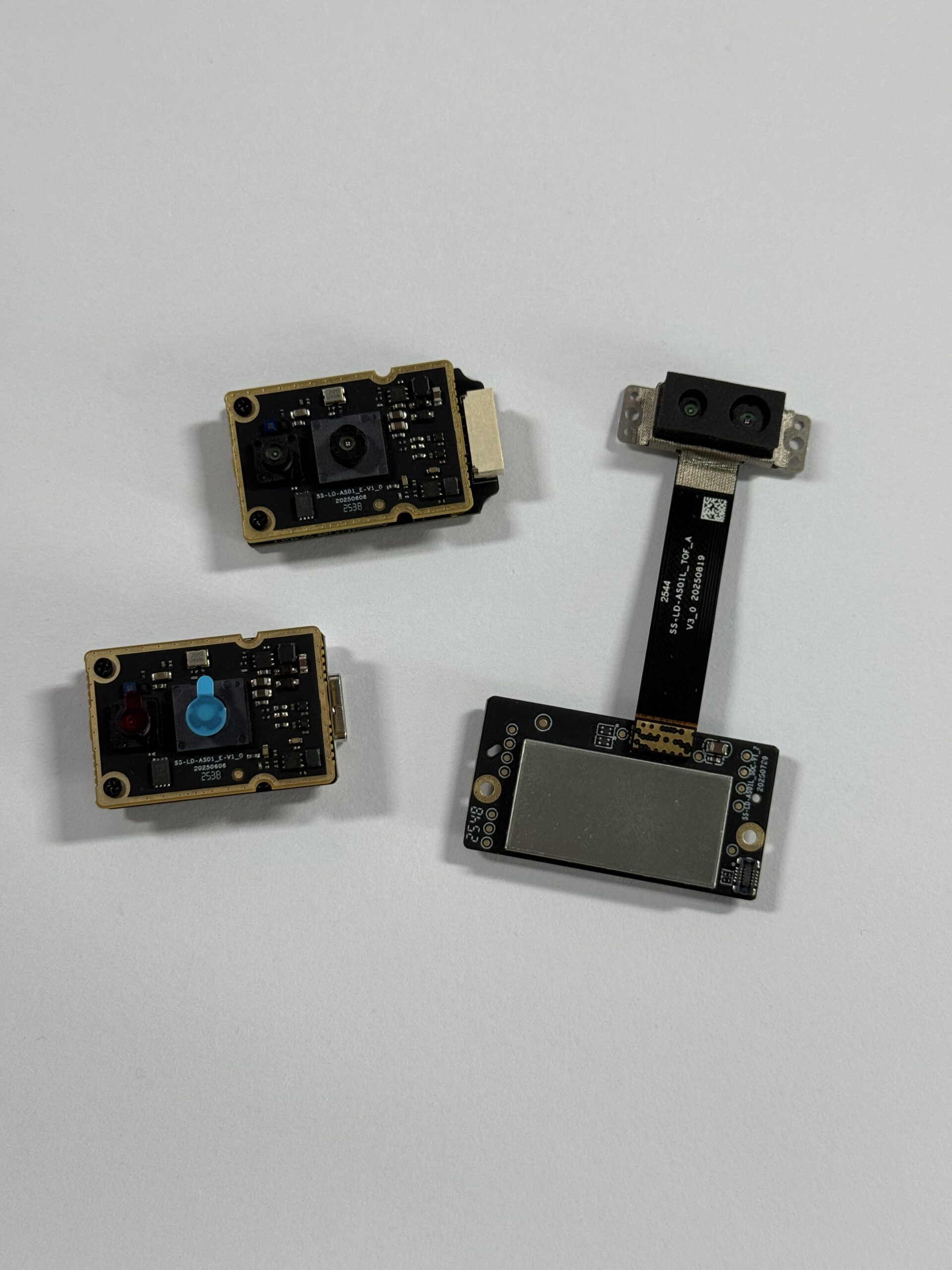
a short-flex design and a long-flex design for different robotics and UAV d…
6. Deep-Dive Technical FAQ
Where can I find free or affordable LiDAR maps for GIS or real-world modeling?
Can I overlay LiDAR map data onto Google Earth or gaming engines?
How do I generate my own LiDAR maps for AGV or UAV projects?
What is the advantage of using SPAD dToF for outdoor LiDAR mapping?
📚 References & Further Reading
- Industry Standard: Hesai Technology Comparison – LiDAR Architectures
- Technical Foundation: IEEE Photonics Society – SPAD and dToF Evolution
- Regulatory & Data: USGS 3DEP Program – National LiDAR Maps