

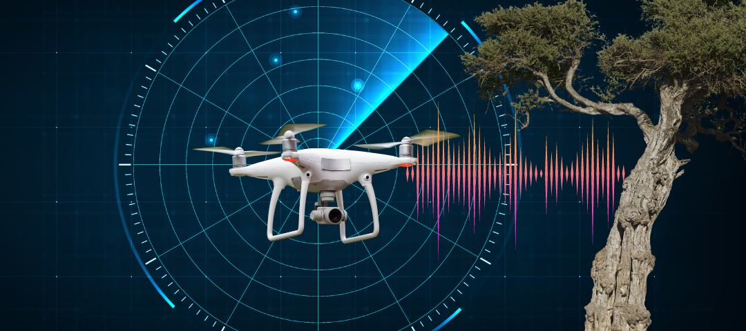
Drone Obstacles: How to Build Smarter UAV Obstacle Detection and Avoidance with dToF LiDAR
Drone obstacles are not just trees, walls, and power lines anymore. In the industrial world, obstacles show up as bridge beams, warehouse racks, dam structures, scaffolding, construction equipment, people, cables, moving vehicles, and uneven terrain that appears at the worst possible moment during low-altitude flight. Look, anyone who has flown near real infrastructure knows the problem: the obstacle is rarely clean, flat, centered, and easy to see.
This guide breaks down how to build a smarter UAV obstacle detection and avoidance stack using solid-state dToF LiDAR. The focus is practical integration for drones, robots, embedded platforms, and autonomous inspection systems. We will cover how drone obstacle sensing works, why perception-to-control integration matters, how depth maps and point clouds support collision avoidance, and where a compact module like the DTOF Solid State LiDAR HM-LD1 can fit into UAV applications such as altitude hold, terrain following, zone detection, and autonomous navigation.
Table of Contents
- 👉 What Are Drone Obstacles?
- 👉 Why Drone Obstacle Avoidance Often Fails
- 👉 Drone Obstacle Sensor Options Compared
- 👉 How dToF LiDAR Helps Drones Detect Obstacles
- 👉 From Detection to Avoidance: Perception-to-Control Architecture
- 👉 DTOF Solid State LiDAR HM-LD1 for UAV Obstacle Detection
- 👉 How to Integrate dToF LiDAR into a Drone Platform
- 👉 Industrial UAV Use Cases for Obstacle Detection
- 👉 Engineering Checklist for Drone Obstacle Avoidance
- 👉 Drone Obstacles FAQ
What Are Drone Obstacles?
Drone obstacles are any objects, structures, surfaces, or environmental conditions that can threaten safe UAV flight. In consumer drone conversations, people usually mean obvious hazards such as trees, buildings, and people. In industrial UAV engineering, the list gets a lot uglier. We are talking about bridge beams, dam walls, expressway structures, cranes, warehouse racks, utility poles, scaffolding, industrial machines, moving vehicles, animals, cables, uneven terrain, and thin objects with poor reflectivity.
Here’s the deal: the real challenge is not only identifying drone obstacles. The real job is detecting them early enough, accurately enough, and consistently enough for the flight controller to do something useful. A concrete wall is easier than a cable. A static dam face is easier than a forklift moving through a warehouse aisle. A bright textured surface is easier for vision systems than a dark, glossy, angled surface in bad lighting.
It is also important to separate obstacle detection from obstacle avoidance. Detection means the UAV senses distance, depth, or object presence. Avoidance means the system turns that information into safe behavior. A sensor can report an obstacle nearby, but the drone still needs logic to slow down, stop, climb, descend, sidestep, reroute, or warn the operator. In the shop, that difference is where many prototypes fall apart.
In infrastructure inspection, warehouse automation, mining, agriculture, emergency response, security patrol, and construction monitoring, obstacles rarely wait in a neat test pattern. GPS may be weak. The aircraft may fly close to steel, concrete, machinery, or terrain. Reaction time may be short. A robust obstacle detection system needs useful distance information, stable update rates, suitable field of view, reliable mounting, and integration options that allow flight software to act on the data.
Why Drone Obstacle Avoidance Often Fails
A common frustration is that a drone can appear to “see” an obstacle but still fail to avoid it. That is because obstacle avoidance is not one function. It is a chain: sensing, filtering, timing, coordinate conversion, local decision-making, and flight control. If one link is weak, the whole system gets unreliable.
Detection Is Only the First Layer
Many prototype UAV systems start with raw range data. A developer connects a sensor, reads a distance value, and triggers a warning below a threshold. That can work on a bench. It can even work in a slow indoor demo. But real drone obstacles need more than a single number. Industrial UAVs benefit from depth images, point clouds, confidence checks, region-of-interest analysis, and vehicle-aware safety margins.
For teams comparing LiDAR with other 3D perception systems, this overview of 3D depth camera robotics gives useful background on how depth sensing supports autonomy. The key point is simple: perception has to be connected to action. A drone with depth data but no control strategy is not avoiding obstacles. It is only watching them.
Common Failure Points in UAV Avoidance Systems
Sensor blind spots are one of the biggest problems. A single forward-facing sensor cannot protect the rear, top, bottom, or sides unless the field of view and mounting position cover those zones. A forward sensor may protect straight flight, but not lateral movement, yaw maneuvers, reverse motion, or landing.
Latency is another killer. If the sensor frame rate is slow, the interface is delayed, or the companion computer is overloaded, the UAV may react too late. Poor field of view can create the same problem because hazards outside the sensing cone are not detected until the drone is already close. At flight speed, even a small processing delay becomes real distance traveled before the avoidance command takes effect.
Bad data fusion can also cause expensive surprises. UAV systems often combine GPS, IMU, barometer, optical flow, LiDAR, camera, and flight-controller data. If timestamps, coordinate frames, or mounting angles are wrong, the obstacle may be mapped to the wrong place. The drone may avoid empty air while flying toward the actual hazard.
Why Perception-to-Control Integration Matters
A practical UAV avoidance stack starts with sensor acquisition, then moves through filtering, obstacle segmentation, local mapping, decision logic, and flight control. For example, a forward depth frame may be filtered to remove outliers, evaluated in the central region of interest, converted into a local obstacle zone, and used to reduce forward velocity or trigger a stop.
Testing is the final gate. A system that works indoors against a flat wall can fail outdoors against reflective metal, black rubber, vegetation, cables, dust, or vibration. Real validation should include static obstacles, moving obstacles, thin objects, multiple lighting conditions, and realistic flight speeds.
Drone Obstacle Sensor Options Compared
There is no universal best sensor for every UAV obstacle avoidance system. The right choice depends on range, weight, power, cost, field of view, resolution, environmental conditions, and software integration. Many industrial drones use more than one sensing technology because every sensor has blind spots. The broader LiDAR market includes autonomy companies such as Innoviz Technologies, which shows how central depth sensing has become across vehicles, robots, and UAV platforms.
Camera-Based Obstacle Detection
Monocular cameras are lightweight, affordable, and rich in visual detail. They are strong for inspection, object recognition, tracking, and AI-based scene understanding. But a single camera does not directly measure distance without algorithms, motion cues, learned depth estimation, or additional supporting data.
Stereo cameras improve depth perception by comparing two images, but they can struggle with low-texture surfaces, glare, repetitive patterns, darkness, vibration, and compute load. AI vision can recognize a person, vehicle, or gate, but recognition is not the same as safe clearance measurement.
Ultrasonic Sensors
Ultrasonic sensors are common in low-cost UAV projects and short-range landing systems. They are useful for simple altitude hold, indoor floor detection, and basic proximity warnings. Their limitations are significant for industrial work: low angular resolution, limited range, slow update behavior in some configurations, and sensitivity to soft, angled, or irregular surfaces.
Radar Sensors
Radar is valuable in fog, dust, rain, smoke, or poor visibility. It can detect objects at longer distances and is less dependent on visible light. The tradeoff is lower spatial detail than LiDAR or depth cameras. For UAVs, radar can be excellent for harsh-environment awareness, but it often needs to be paired with other sensors for fine local navigation.
LiDAR Sensors
LiDAR directly measures distance and can generate geometric information about the environment. Depending on the module, LiDAR can support distance detection, point clouds, depth maps, obstacle avoidance, mapping, SLAM, terrain following, landing assistance, and zone monitoring. Compared with a single-point rangefinder, a depth LiDAR module gives the aircraft more spatial context.
dToF LiDAR for Compact UAVs
Direct Time-of-Flight, or dToF, LiDAR emits light pulses and measures how long reflected photons take to return. The sensor calculates distance from that travel time. SPAD-based dToF technology supports compact solid-state modules, which is attractive for drones because it reduces size, weight, and mechanical complexity compared with many larger scanning systems.
| Sensor Type | Strengths | Limitations | Best UAV Fit |
|---|---|---|---|
| Monocular Camera | Low cost, rich image data, AI object recognition | Depth estimation depends on algorithms and lighting | Visual tracking, inspection, recognition |
| Stereo Camera | Passive depth sensing, useful for close to mid-range | Can struggle with low texture, glare, and low light | Indoor navigation, robotics, visual SLAM |
| Ultrasonic | Simple, low cost, useful at short range | Limited resolution and range; affected by surface angle | Basic altitude hold, landing assistance |
| Radar | Works in dust, fog, and poor visibility | Lower spatial detail, more complex processing | Longer-range detection, harsh environments |
| dToF LiDAR | Direct distance measurement, depth map, point cloud output | Requires correct integration with control logic | Obstacle detection, terrain following, UAV navigation |
How dToF LiDAR Helps Drones Detect Obstacles
dToF LiDAR is useful for drone obstacles because it provides direct distance measurement instead of depending only on image interpretation. A dToF sensor emits light pulses, receives reflected photons, and calculates distance from measured time delay. In a depth module, this creates a depth map or 3D point cloud that gives the UAV more context than a single range value.
What Is dToF LiDAR?
dToF means direct Time-of-Flight. The sensor sends a light pulse toward the scene. When the pulse reflects from an object and returns to the receiver, the system measures travel time and calculates distance. SPAD-based dToF modules use sensitive photon detection to support compact depth sensing. Solid-state LiDAR is also being advanced by specialist companies such as SOS LAB, reflecting the industry-wide move toward compact, robust perception modules.
Unlike a simple single-point rangefinder, a depth-capable dToF LiDAR can represent a scene as many distance measurements across a field of view. That matters because drone obstacles are rarely simple points. A wall, rack, vehicle, bridge beam, or dam surface has shape, position, and spatial extent.
Why Depth Maps Matter for Drone Obstacles
A single distance number may tell a drone something is nearby, but it may not reveal whether the object is centered in the flight path, near the edge of the sensor view, part of the ground, or just a temporary outlier. A depth map helps identify object shape, relative position, and safe direction. That supports forward obstacle warning, landing zone evaluation, wall following, corridor navigation, terrain following, and dynamic safety zones.
Why Field of View Matters
Field of view determines how much of the environment a sensor can observe at once. A narrow field may miss obstacles outside the sensing cone, while a wider field gives the software more local context. The DTOF Solid State LiDAR HM-LD1 provides a 60° horizontal by 45° vertical field of view, which is useful for forward-facing obstacle detection on compact UAV platforms.
Outdoor Ranging Considerations
Outdoor obstacle detection is affected by ambient light, target reflectivity, angle of incidence, weather, surface texture, vibration, and mounting position. The HM-LD1 specifies indoor ranging from 0.5 to 25 m and outdoor ranging from 0.2 to 8 m. For low-speed inspection, approach control, and obstacle warning, an outdoor range up to 8 m can be useful when the UAV is operating close to infrastructure and moving at controlled speeds.
Need compact depth sensing for UAV obstacle detection?
The DTOF Solid State LiDAR HM-LD1 provides real-time depth data, 40 × 30 resolution, 10 fps frame rate, 60° × 45° FOV, and UART / UDP / UVC interfaces for embedded UAV and robotics development.
From Detection to Avoidance: Perception-to-Control Architecture
The technical heart of drone obstacle avoidance is the connection between perception and control. The sensor tells the system what is nearby. The UAV still has to turn that information into safe motion. A proper architecture includes sensor acquisition, filtering, obstacle segmentation, local mapping, decision logic, and flight-controller commands.
Layer 1 — Sensor Data Acquisition
Sensor acquisition starts with the interface and data format. UART is useful for embedded systems and lightweight communication. UDP can support network-based transmission to a companion computer. UVC can make depth data easier to handle in camera-like workflows on PCs and Linux platforms. The HM-LD1 supports UART, UDP, and UVC, giving developers flexibility across prototype and deployment environments.
Frame rate and resolution matter too. The HM-LD1 provides 40 × 30 resolution and a 10 fps frame rate. That must be matched to vehicle speed, stopping distance, processing delay, and avoidance behavior. A slow inspection UAV flying near a bridge surface has different needs than a high-speed racing platform.
Layer 2 — Filtering and Obstacle Segmentation
Raw depth data should be filtered before it is used for control. Filtering may include noise reduction, median filters, confidence thresholds, region-of-interest selection, ground separation, and outlier rejection. For a forward-facing system, the software may focus on the central region of the depth map because that region corresponds most closely to the current flight path.
Segmentation separates meaningful obstacles from background, ground, or sensor artifacts. In terrain following, the ground may be expected. In a warehouse aisle, racks, walls, boxes, forklifts, and people may require different responses. That tuning needs to fit the mission, not just a sample project.
Layer 3 — Local Obstacle Map
After filtering, depth frames can be converted into local 3D coordinates and used to create an occupancy representation around the UAV. A local obstacle map helps define no-fly zones, estimate free space, and track moving objects across frames. When the drone moves, that map must be updated using vehicle motion estimates from the IMU, optical flow, visual odometry, or other navigation sensors.
Layer 4 — Flight Controller Decision Logic
The decision layer defines what the drone should do when an obstacle is detected. Possible actions include stopping, slowing down, climbing, descending, sidestepping, rerouting, returning home, or warning a manual pilot. A sensor alone cannot guarantee avoidance because it does not command the motors or define mission-level behavior.
Inspection platforms such as a drone with thermal camera can benefit from obstacle sensing when operating near buildings, power infrastructure, or industrial equipment. In those missions, the payload captures inspection data while the obstacle system helps maintain safe distance.
Layer 5 — Companion Computer and Middleware
Many UAV obstacle avoidance systems use a companion computer such as a Raspberry Pi, Jetson-class board, x86 Linux computer, ARM Linux platform, or Windows development machine. Middleware may include ROS, OpenCV, custom C or Python applications, and MAVLink-based communication with PX4 or ArduPilot-style flight stacks. The companion computer can receive the depth stream, process the data, build local obstacle logic, and send velocity constraints or avoidance commands to the flight controller.
DTOF Solid State LiDAR HM-LD1 for UAV Obstacle Detection
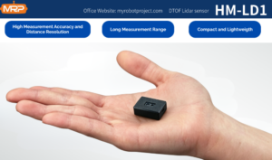
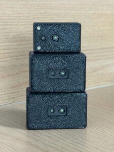
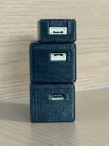
The DTOF Solid State LiDAR HM-LD1 is a compact SPAD dToF LiDAR module designed for real-time depth perception, obstacle detection, distance measurement, and robotic vision development. For UAV applications, its low weight, low power consumption, depth image output, and multiple interfaces make it suitable for drone obstacle detection, altitude hold, terrain following, autonomous navigation experiments, and smart inspection platforms.
DTOF Solid State LiDAR HM-LD1 supports real-time depth images and 3D point cloud data for environmental perception. It is designed for drones, robots, cameras, security systems, PCs, Raspberry Pi, flight-controller companion computers, and embedded platforms. Its application range includes obstacle avoidance, distance detection, autonomous navigation, smart inspection, robotic vision development, UAV altitude hold, terrain following, robot navigation, SLAM, autofocus, user presence detection, object recognition, volume measurement, and zone intrusion monitoring.
Download the DTOF SSL HM-LD1 Product Brochure for additional product information and integration planning.
| Specification | DTOF Solid State LiDAR HM-LD1 |
|---|---|
| Product Name | DTOF Solid State LiDAR HM-LD1 |
| Technology | SPAD dToF solid-state LiDAR |
| Dimension | 43.5 mm × 30 mm × 26.5 mm |
| Weight | 28 g |
| Ranging Capability | Indoor: 0.5–25 m; Outdoor: 0.2–8 m |
| Ranging Accuracy | ±3 cm |
| Field of View | 60° horizontal × 45° vertical |
| Resolution | 40 × 30 |
| Frame Rate | 10 fps |
| Interface | UART / UDP / UVC |
| Operating Temperature | -20 ℃ to 60 ℃ |
| Power Consumption | 1.2 W |
| Typical Applications | Drone obstacle detection, UAV altitude hold, terrain following, robot navigation, SLAM, distance detection, zone intrusion monitoring, robotic vision development |
View Product Details & Pricing ➔
Why HM-LD1 Fits Compact UAV Platforms
Weight and power are critical design constraints in drone obstacle sensing. At 28 g, the HM-LD1 is suitable for compact UAVs where payload mass affects flight endurance, handling, and stability. Its 1.2 W power consumption helps reduce the onboard power burden compared with heavier perception payloads. The 60° × 45° field of view supports forward obstacle detection, and the specified outdoor range up to 8 m can be useful for low-speed inspection, approach control, and collision warning.
The module’s UART, UDP, and UVC interfaces simplify integration with PCs, Raspberry Pi systems, embedded boards, and companion computers used in UAV development. MRP also offers SDKs for x86 Windows, x86 Linux, and ARM Linux, enabling integration across diverse operating systems and processor architectures. Teams comparing dToF LiDAR with other compact depth sensing modules can also review the 3D depth camera P100R for broader robotic perception projects.
Point Cloud and Depth Map Output
Depth data can be displayed as point cloud information and depth map information, helping developers evaluate distance distribution across the scene. For drone obstacles, this is more useful than a single range reading because the software can identify whether the object is in the central path, near the edge, above the expected flight line, or part of the ground.
How to Integrate dToF LiDAR into a Drone Platform
Successful dToF LiDAR integration starts with a clear mission definition. A drone designed for low-speed bridge inspection has different requirements from a warehouse inventory drone, an agriculture terrain-following platform, or an FPV autonomy experiment. Before setting thresholds or writing control logic, engineers should define which obstacles must be detected, from which direction, at what speed, and under which environmental conditions.
Step 1 — Define the Obstacle Detection Direction
⚙️ Forward sensing is common for obstacle warning during normal flight. ⚙️ Downward sensing supports altitude hold, terrain following, landing assistance, and ground clearance monitoring. ⚙️ Side sensing may be needed for wall following, corridor navigation, warehouse aisle flight, or structure inspection. ⚙️ Rear protection may matter when drones reverse or operate in confined spaces. Full coverage usually requires multiple sensors or sensor fusion.
Step 2 — Select the Interface
The HM-LD1 supports UART, UDP, and UVC interfaces. UART is useful for lightweight embedded integration. UDP is suitable for network-based transmission to a companion computer. UVC can be convenient when the depth stream is processed similarly to a camera feed on Linux, Windows, or vision-processing platforms.
Step 3 — Mount and Calibrate the Sensor
Mechanical mounting is a major reliability factor. The LiDAR should be mounted rigidly to reduce vibration and prevent angle changes during flight. The optical window should not be blocked by propellers, landing gear, payload brackets, cables, or covers. The sensor frame should be aligned with the drone body frame, and pitch, yaw, and roll offsets should be recorded for software compensation.
Step 4 — Process Depth Data
Depth processing may include frame acquisition, region-of-interest filtering, thresholding, obstacle clustering, distance-to-collision estimation, velocity-based safety zones, and free-space evaluation. A slow drone may use a shorter safety margin than a faster aircraft, but every system must account for latency and braking behavior.
Step 5 — Connect to Flight Logic
The companion computer can send velocity constraints, stop commands, avoidance requests, or warning messages to the flight controller. The flight controller should enforce stable motion and prevent unsafe commands. Manual pilot override should remain available during testing and deployment.
Step 6 — Validate Indoors and Outdoors
Validation should include wall tests, thin obstacle tests, outdoor daylight tests, low-light tests, moving object tests, vibration checks, flight-speed tests, emergency stop tests, and false positive or false negative logging. Indoor success does not guarantee outdoor reliability. The safest approach is to test gradually, record data, tune thresholds, and expand the operating envelope only after the system behaves predictably.
Industrial UAV Use Cases for Obstacle Detection
Industrial UAVs often fly closer to structures than consumer drones. That makes obstacle detection more than a convenience. It becomes mission-enabling technology. A drone that can maintain safe standoff distance, detect nearby objects, and support controlled approach can reduce pilot workload and improve repeatability.
Infrastructure Inspection
Bridge, expressway, dam, tower, facade, and industrial plant inspection often requires drones to fly near beams, cables, walls, ledges, and machinery. The HM-LD1’s outdoor ranging capability up to 8 m can support low-speed approach control and standoff distance measurement in suitable conditions.
Warehouse and Indoor Drone Navigation
Indoor drones may operate in GPS-denied environments with racks, aisles, boxes, people, forklifts, and narrow spaces. Indoor or nighttime ranging up to 25 m is relevant for warehouse navigation, inventory scanning, security patrol, and indoor inspection.
Terrain Following and Altitude Hold
A downward or angled dToF LiDAR can support terrain following and altitude hold for agriculture, surveying, slope inspection, and low-altitude flight. Uneven ground, sudden rises, embankments, and cliffs can become drone obstacles when the aircraft flies close to the surface.
FPV Training, Racing, and Autonomous Experiments
Obstacle sensors can support FPV training, course boundary monitoring, collision warnings, and autonomous tracking experiments. High-speed racing needs very low latency and careful system design, but lower-speed training and research platforms can benefit from depth-based warnings and safety zones.
Security and Zone Intrusion Monitoring
Beyond flight safety, dToF LiDAR can support zone intrusion monitoring, object presence detection, and robotic patrol systems. A UAV or ground robot can use depth information to detect whether an object or person enters a defined zone.
Engineering Checklist for Drone Obstacle Avoidance
Before committing to a drone obstacle detection architecture, engineering teams should verify that the sensor, software, mechanical design, and flight logic are aligned. Here is the practical shop-floor checklist.
- ✅ Obstacle direction: Define whether the UAV needs forward, downward, side, rear, or 360° sensing.
- ✅ Detection range: Match range requirements to flight speed and stopping distance.
- ✅ Field of view: Ensure the sensor covers the expected obstacle zone.
- ✅ Weight: Confirm payload impact on flight endurance and stability.
- ✅ Power consumption: Verify onboard power budget and thermal conditions.
- ✅ Frame rate: Confirm the update rate is sufficient for vehicle speed.
- ✅ Interface: Choose UART, UDP, UVC, or another interface based on the computing architecture.
- ✅ Data output: Decide whether the system needs single distance values, depth maps, or point clouds.
- ✅ Companion computer: Plan where filtering, mapping, and avoidance logic will run.
- ✅ Flight controller integration: Define how obstacle data becomes velocity, stop, climb, or reroute commands.
- ✅ Environment: Test lighting, reflectivity, dust, vibration, and temperature conditions.
- ✅ Fail-safe behavior: Define what happens when sensor data is lost or unreliable.
Need a compact dToF LiDAR module for UAV obstacle detection or robotic vision development? View the DTOF Solid State LiDAR HM-LD1 specifications or download the product brochure.
Build smarter drone obstacle detection with dToF LiDAR
Explore the HM-LD1 solid-state dToF LiDAR module for UAV obstacle detection, altitude hold, terrain following, robotics, and autonomous navigation development.
Drone Obstacles FAQ
Why does my drone see obstacles but fail to avoid them?
What is the best sensor for small drones that need obstacle avoidance without adding too much weight?
Can obstacle avoidance sensors help FPV training, drone racing, or autonomous tracking projects?
Is LiDAR better than a camera for drone obstacle detection?
How much obstacle detection range does a drone need?
Can one LiDAR sensor provide full drone obstacle avoidance?
What interface should I use for connecting a LiDAR module to a drone?
📚 References & Further Reading
- Industry Standard: Innoviz Technologies | SOS LAB
- Related Guide: 3D depth camera robotics | DTOF Solid State LiDAR HM-LD1 | 3D depth camera P100R | drone with thermal camera






