


What Is LiDAR Sensor Technology? A Buyer’s Guide for Robotics and Automation
A mobile robot cannot avoid a pallet, map a warehouse, or line up with a docking station unless it can measure the space around it. Cameras are excellent at showing color, texture, labels, and other visual details, but a conventional RGB camera does not directly measure distance. A LiDAR sensor fills that gap by sending out laser light, detecting the return, and converting the result into distance values, depth images, or 3D point clouds.
Here’s the deal: LiDAR is not one magic component with one standard behavior. A compact module may measure a single point, scan a horizontal plane, or produce a rectangular depth image. A larger system may generate a dense 3D map. The right choice depends on what the machine must detect, how fast it moves, and what the environment does to the optical signal.
Range, field of view, angular or pixel resolution, frame rate, target reflectivity, interface options, power consumption, and software support all matter. A sensor that looks impressive on a datasheet may struggle with black plastic, direct sun, glass, dust, or a small object near the edge of its field of view. This guide walks through the technology, the main architectures, the specifications that deserve scrutiny, and a practical test plan for robotics, drones, machine vision, security, and industrial automation.
Look at LiDAR as part of a complete perception system rather than as an isolated box. The mount, window, cable, host computer, driver, calibration file, timestamp path, and control software all influence the final result. In the shop, those integration details are often what separate a promising prototype from a reliable machine.
Table of Contents
- ✅ What Is a LiDAR Sensor?
- ⚙️ How Does a LiDAR Sensor Work?
- ✅ What Data Does a LiDAR Sensor Produce?
- ✅ Types of LiDAR Sensors
- ⚙️ LiDAR Specifications Buyers Must Compare
- ✅ Indoor and Outdoor LiDAR Performance
- ⚙️ Hardware and Software Integration
- ✅ Robotics and Automation Applications
- ✅ HM-LD1 dToF Solid-State LiDAR Specifications
- ⚙️ How to Choose a LiDAR Sensor
- ⚙️ How to Validate a LiDAR Sensor
- ✅ LiDAR vs. Cameras, Radar, and Ultrasonic Sensors
- ✅ Frequently Asked Questions
- ✅ Choosing the Right LiDAR Senso
In brief: A LiDAR sensor uses emitted laser light and the detected return signal to measure distance. Depending on its design, it can output a single distance, a two-dimensional scan, a depth image, or a three-dimensional point cloud.
What Is LiDAR Sensor?
A LiDAR sensor is an optical ranging device. It emits laser light, watches for reflected energy, and calculates how far away the reflecting surface is. Repeating that measurement across multiple directions creates useful geometry for obstacle detection, localization, mapping, inspection, terrain following, and automated decisions.
The term LiDAR is commonly expanded as “Light Detection and Ranging.” It describes a family of light-based ranging technologies, not a single product format. One unit may point straight ahead and return one distance. Another may scan a plane, while an array-based module may capture a rectangular depth image without rotating through the scene.
The practical difference between LiDAR and a standard RGB camera is the measurement being made. A camera records image intensity and color. Stereo cameras, structured-light systems, motion analysis, and machine-learning models can estimate depth, but a normal monocular RGB image does not directly contain a measured distance at every pixel. LiDAR actively measures geometry from an optical return.
That distinction does not make every LiDAR suitable for every robot. Suitability comes down to range, minimum working distance, accuracy, repeatability, field of view, spatial resolution, update rate, ambient-light tolerance, target behavior, power, size, mounting, interface, and software. The sensor has to work in the actual machine, not just on a clean laboratory target.
a short-flex design and a long-flex design for different robotics and UAV d…
One more point is worth making early: LiDAR does not identify an object by itself. It measures spatial structure. A camera or a trained vision model may be better at distinguishing a person from a pallet, while LiDAR may be better at determining the object’s position and distance. Many industrial systems get the best results by combining the two.
How Does a LiDAR Sensor Work?
1. Light Emission and Return Detection
A measurement starts when the laser source emits a pulse or modulated optical signal. The light travels through the optics and into the surrounding scene. When it strikes an object, some of that energy may reflect toward the receiver. The detector captures the return, and the electronics estimate the time, phase, or frequency information needed to calculate distance.
A single-point rangefinder repeats this process in one direction. A scanning unit redirects the beam across several angles. An array-based device measures several positions at once within a fixed field of view. The output may be a stream of distance values, a depth frame, a line scan, or a point cloud.
Return strength depends on more than distance. Surface reflectivity, color, finish, curvature, incidence angle, ambient light, atmospheric particles, optical transmission, receiver sensitivity, and filtering all play a role. This is why a maximum-range number without test conditions is only a rough reference.
2. Direct Time of Flight
Direct time of flight, or dToF, measures the interval between the outgoing light and the returning signal. The basic relationship is:
Distance = (Speed of light × Measured round-trip time) ÷ 2
The division by two matters because the light makes a complete trip: sensor to target and target back to sensor. Since light travels so quickly, the timing interval is extremely short. Accurate dToF therefore requires specialized timing electronics, sensitive detectors, calibration, optical filtering, and signal processing.
Some compact dToF modules use SPAD detectors. SPAD stands for single-photon avalanche diode. These devices can respond to very small amounts of returned optical energy and can be arranged in arrays for depth measurement. Still, dToF describes a measurement method, not a guaranteed range or accuracy level. Two dToF products can behave very differently because their emitters, optics, detectors, filters, timing circuits, and software are different.
3. From Return Signals to Depth Data
The raw return is not yet a useful robot measurement. The electronics must identify valid returns, reject noise, reduce the influence of ambient light, and apply calibration. Depending on the device, the output may include distance, confidence, intensity, validity, and timestamp information.
Host software may discard invalid samples, convert depth pixels into Cartesian coordinates, cluster points, estimate planes, or fuse LiDAR with camera and inertial data. Point-cloud quality is therefore affected by calibration, coordinate transforms, timestamp accuracy, filtering, and host processing as much as by the optical module.
What Data Does a LiDAR Sensor Produce?
Distance Measurements
The simplest output is one distance per measurement cycle. That is enough for altitude control, proximity detection, material-level measurement, autofocus assistance, trigger logic, and presence detection. The tradeoff is coverage: a single-point sensor does not describe a broad scene unless the platform moves or another mechanism scans the environment.
Depth Maps
A depth map is a two-dimensional grid in which each valid pixel stores a measured distance. A 40 × 30 device has 1,200 measurement positions before invalid-point handling and filtering. Do not compare that number directly with the megapixel count of an RGB camera. A depth grid describes geometry; a color image describes appearance.
Depth maps work well for obstacle masks, presence zones, foreground separation, region-based detection, and image-style processing. Their usefulness depends on whether the object occupies enough depth samples at the required distance and viewing angle.
3D Point Clouds
A point cloud represents measurements as three-dimensional coordinates, usually X, Y, and Z. Depending on the system, each point may also include intensity, confidence, validity, or a timestamp. Point clouds support obstacle extraction, plane fitting, terrain analysis, mapping, localization, volume estimation, surface inspection, and scene segmentation.
Coordinate Frames and Timestamps
Raw LiDAR data begins in the sensor’s own coordinate frame. A robot may need the same data expressed in a body, vehicle, manipulator, camera, or world frame. Extrinsic calibration defines the sensor’s position and orientation relative to the host machine.
Timestamps matter whenever the sensor or platform moves. If measurements are captured at different times but treated as though they came from one static pose, the resulting point cloud can be distorted. That problem shows up quickly in fast-moving robots, drones, and tightly coupled localization systems.
Types of LiDAR Sensors
Single-Point LiDAR
Single-point LiDAR concentrates on one measurement direction. It is a sensible choice for altitude control, focused clearance measurement, trigger logic, and compact proximity systems. It usually keeps bandwidth and processing demand low, but it cannot produce a wide-area scene without platform movement or an external scanner.
Mechanical Scanning LiDAR
Mechanical scanning LiDAR uses a rotating or moving optical assembly to sweep through a scene. This architecture can provide broad angular coverage and a dense sequence of samples. The cost is usually paid in size, moving parts, power, vibration sensitivity, mounting requirements, and mechanical durability.
Solid-State LiDAR
Solid-state LiDAR generally avoids a continuously rotating mechanical assembly. That can make the package smaller, lighter, and easier to seal or embed in a machine. It is attractive for mobile robots, drones, smart cameras, security equipment, and other applications with tight space or payload limits.
Do not read too much into the label. A solid-state product may have a fixed field of view, modest depth resolution, application-specific range, or an update rate intended for local perception rather than long-range mapping. Compare the actual performance envelope instead of assuming that solid-state automatically means superior.
Flash and Array-Based Depth LiDAR
Flash and array-based systems measure multiple positions without mechanically sweeping one point across the full scene. They can produce depth frames for obstacle zones, presence monitoring, volume measurement, compact robotic vision, and smart-space applications. Resolution, illumination pattern, range, ambient-light tolerance, and invalid-return behavior vary by design.
dToF, Indirect ToF, and FMCW
dToF estimates distance from direct round-trip travel time. Indirect time of flight generally uses phase relationships in modulated light. Frequency-modulated continuous-wave, or FMCW, LiDAR uses frequency modulation and may provide velocity-related information depending on the implementation. None of these architectures wins every application. The complete optical, electronic, mechanical, and software design is what determines field performance.
LiDAR Specifications Buyers Must Compare
Measurement Range
Range is conditional, not absolute. Ask whether the quoted maximum applies indoors, at night, in indirect daylight, or in direct sunlight. Ask what target reflectivity, target size, target angle, ambient illuminance, and valid-return threshold were used. A maximum measured return is not necessarily a dependable detection distance.
Minimum range deserves equal attention. A near-field blind zone can cause a robot to lose sight of an object after moving too close. Check whether the complete field of view shares the stated range and whether edge positions behave differently from the center.
Accuracy, Precision, and Repeatability
Accuracy is closeness to the true distance. Precision describes how closely repeated readings agree. Repeatability is the ability to reproduce results under comparable conditions. Resolution may refer to distance increments, pixel count, or angular sampling, so the term needs context.
A sensor can be precise but inaccurate if all readings cluster around a biased value. It can also be accurate on average while individual readings vary widely. A proper evaluation should report mean error, maximum error, standard deviation, invalid-return rate, and dropped frames over the intended operating envelope.
Field of View
Field of view defines the angular area observed by the sensor. A wider field can improve scene coverage and reduce the number of sensors required. However, if the sample count remains fixed, spreading those samples over a wider angle increases the spacing between measurement positions.
Spatial Resolution
Depth-array resolution, scanning angular resolution, and distance resolution are different specifications. A 40 × 30 output means 40 horizontal by 30 vertical depth samples. It does not represent camera-grade visual detail. Object detectability depends on object size, range, field of view, mounting position, and angle.
Frame Rate and Latency
Frame rate tells you how often the sensor updates, but not how quickly the robot receives and acts on a measurement. Acquisition, onboard processing, data transfer, host decoding, filtering, coordinate conversion, and application logic all add delay. A nominal 10 fps sensor has a 100-millisecond frame interval before those other delays are counted.
Reflectivity, Color, and Target Angle
Dark or absorbent materials may return less optical energy. Glossy, mirrored, transparent, curved, or steeply angled surfaces may redirect light, produce multiple returns, or create inconsistent readings. Test the actual plastics, fabrics, metals, films, glass, packaging, and floor surfaces found in the deployment.
Power, Weight, and Mechanical Envelope
Power affects battery capacity, heat generation, regulator selection, and operating time. Weight matters on drones and mobile platforms. Dimensions affect enclosure design, mounting rigidity, optical clearance, connector access, cleaning access, and cable routing.
Procurement rule: Never approve a LiDAR sensor from the maximum-range number alone. Compare minimum distance, target properties, ambient light, field of view, update rate, interfaces, mechanical fit, power, software maturity, and supplier support.
Indoor and Outdoor LiDAR Performance
Ambient Light and Sunlight
Sunlight adds optical background energy and can make weak returns harder to identify. Outdoor range may therefore be shorter than indoor or nighttime range. Optical filters, emitter design, detector sensitivity, timing methods, target reflectivity, target angle, and signal processing all influence the result.
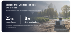
The HM-LD1 provides a useful example. Its supplied specifications state an indoor or nighttime capability of up to 25 meters and an outdoor daytime capability of up to 8 meters. Product information also references measurements at 8 meters under clear summer daylight conditions of approximately 80,000 lux. Treat those values as an evaluation baseline, then test the actual target, enclosure, mounting angle, and sunlight direction.
Weather and Airborne Particles
Fog, rain, dust, smoke, spray, and condensation can scatter or attenuate emitted and returning light. They may also create false returns in front of the intended target. No ingress-protection or weatherproof rating is supplied for the HM-LD1, so environmental protection must not be assumed.
An outdoor enclosure needs its own evaluation. Check window transmission, sealing, condensation, internal reflections, contamination, cleaning access, and the effect of dirt on the optical path.
Temperature and Thermal Stability
Temperature can affect optical output, detector response, electronic timing, and calibration. The HM-LD1 is specified for operation from −20°C to 60°C. Final results still depend on enclosure temperature, airflow, nearby electronics, solar loading, heat dissipation, and installation conditions.
Multi-LiDAR Interference
Warehouses and production facilities may have several optical ranging devices operating at the same time. Interference depends on wavelength, timing, field overlap, sensor placement, optical filtering, firmware, and architecture. If multiple LiDAR units can see the same space, test them simultaneously.
How to Integrate a LiDAR Sensor into a Robot or Drone
Mechanical Integration
The sensor needs a rigid mount that preserves alignment and leaves the field of view open. An enclosure window must provide suitable optical transmission and avoid internal reflections. Account for vibration, heat dissipation, protection from impact, cleaning access, cable routing, dust, and condensation.
Drone installations add propellers, landing gear, body panels, gimbal movement, and vibration to the problem. A downward-facing sensor for altitude control has different requirements from a forward-facing obstacle sensor or an angled terrain sensor.
Electrical and Interface Integration
UART is common in embedded designs. UDP provides network transport, while UVC can provide a standardized video-class path for compatible depth or image streaming implementations. An interface name does not tell you the connector, voltage, pinout, packet format, bandwidth, timestamp behavior, or driver support. Those details must come from current technical documentation.
SDK and Platform Support
Evaluate drivers, APIs, examples, calibration files, data structures, timestamp handling, point-cloud conversion, firmware updates, diagnostics, and version support. The HM-LD1 offers SDK support for x86 Windows, x86 Linux, and ARM Linux. That can simplify work on PCs, industrial computers, and embedded Linux platforms, but architecture, operating system, bandwidth, and driver compatibility still need to be verified.
Calibration and Sensor Fusion
Intrinsic calibration describes the sensor’s internal projection characteristics. Extrinsic calibration establishes its position and orientation relative to the robot, drone, camera, or inertial unit. Time synchronization aligns measurements from different sensors. Poor calibration or timestamp handling can distort a point cloud even when the sensor itself is operating normally.
Mobile systems frequently combine LiDAR with cameras and inertial sensors. Teams developing tightly coupled perception pipelines may also review this guide to implementing ZUPT in visual-inertial odometry, particularly when analyzing motion constraints, stationary updates, and accumulated drift.
LiDAR Applications in Robotics and Automation
AMRs and AGVs
Autonomous mobile robots and automated guided vehicles use depth and range information for obstacle detection, local navigation, docking, aisle monitoring, pallet approach, and map support. Required coverage depends on robot speed, braking capability, sensor height, payload shape, minimum object size, and blind zones.
A general-purpose depth module should not be assumed to meet personnel-protection requirements or replace certified safety equipment. Safety applications require a separate review of certification, failure modes, diagnostics, and stopping performance.
Drones and UAVs
LiDAR can support altitude hold, terrain following, landing assistance, obstacle detection, structural inspection, and mapping. Low mass and low power are important because both affect flight endurance. Range, field of view, update rate, vibration response, and mounting orientation must match flight speed and terrain.
For a broader example of multiple sensing channels in aerial inspection, see the article explaining why a tri-spectral gimbal payload can expand UAV inspection capabilities.
Industrial and Infrastructure Inspection
LiDAR provides standoff measurement, object dimensions, volume estimates, and surface geometry. It can help inspect bridges, dams, expressways, warehouses, tanks, and production equipment. The data may support an inspection workflow, but it does not independently certify structural integrity or replace engineering judgment.
Security and Smart Spaces
Depth sensing can support zone intrusion monitoring, occupancy logic, presence detection, object-size estimation, and privacy-conscious spatial monitoring. A low-resolution depth map may describe where something is without capturing the color or facial detail of an RGB image. Detection thresholds, blind zones, lighting, and false alarms still require real testing.
Machine Vision and Smart Cameras
Machine-vision systems can use LiDAR for autofocus assistance, foreground separation, distance estimation, dimensional checks, and depth-aware automation. LiDAR usually complements rather than replaces a camera: LiDAR provides geometry, while the camera supplies texture, color, text, and semantic detail.
HM-LD1 dToF Solid-State LiDAR Specifications
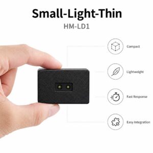
The HM-LD1 dToF solid-state LiDAR is a compact SPAD-based depth module designed to provide real-time depth images and 3D point-cloud data. Its fixed 60° × 45° field of view, 40 × 30 depth resolution, 28 g weight, and multiple interface options make it relevant to embedded robotics, UAV development, smart inspection, presence detection, security monitoring, and machine-vision prototypes.
The module provides indoor ranging from 0.5 to 25 meters and outdoor ranging from 0.2 to 8 meters according to the supplied specifications. Its stated ranging accuracy is ±3 cm. Optical performance still depends on target reflectivity, angle, ambient illumination, temperature, and location within the field of view. Treat the number as a specification to validate, not an unconditional promise.
| Specification | HM-LD1 Value | Buyer Interpretation |
|---|---|---|
| Technology | SPAD dToF solid-state LiDAR | Direct time-of-flight depth sensing without a continuously rotating scanning assembly. |
| Dimensions | 43.5 mm × 30 mm × 26.5 mm | Compact mechanical envelope for embedded devices and space-constrained robots. |
| Ranging capability | Indoor: 0.5–25 m; outdoor: 0.2–8 m | Outdoor range is lower because ambient conditions can affect the optical signal. |
| Ranging accuracy | ±3 cm | Validate across actual distances, target reflectivities, angles, temperatures, and lighting conditions. |
| Field of view | 60° horizontal × 45° vertical | Provides a fixed rectangular sensing area for obstacle and scene-depth detection. |
| Depth resolution | 40 × 30 | Produces up to 1,200 depth sampling positions per frame before validity filtering. |
| Frame rate | 10 fps | Provides ten depth updates per second; total application latency must still be measured. |
| Interfaces | UART, UDP, UVC | Supports embedded serial, network, and compatible video-class integration paths. |
| Operating temperature | −20°C to 60°C | Suitable for a broad temperature range, subject to final enclosure and thermal validation. |
| Power consumption | 1.2 W | Relevant to battery sizing, thermal design, and embedded power budgeting. |
| Weight | 28 g | Useful where payload mass affects robot mobility or drone flight endurance. |
| SDK support | x86 Windows, x86 Linux, ARM Linux | Supports development across desktop, industrial PC, and embedded Linux environments. |
The HM-LD1 makes the most sense where compact size, low weight, moderate power consumption, and a fixed-area depth image matter more than high-density, long-range mapping. Potential uses include short- and medium-range obstacle detection, drone altitude or terrain sensing, robot navigation assistance, smart-camera depth input, presence zones, intrusion monitoring, volume measurement, embedded 3D perception, and prototype SLAM work.
The 40 × 30 resolution should not be presented as a replacement for a high-density mapping LiDAR. Its 1,200 sampling positions are better suited to broad depth structure and object zones than fine visual detail. At greater distances, a small object may occupy only a few samples. Projected sample spacing and testing with real objects are therefore essential.
HM-LD1 supports UVC, UDP, and UART integration paths for PCs, embedded controllers, networked processing systems, and compatible Linux platforms. Connector details, voltage, pinout, packet format, bandwidth, synchronization, and current operating-system compatibility should be confirmed before a production design is frozen.
Review the HM-LD1 product brochure for integration documentation and current product information.
Mechanical data check: The supplied source material contains two different dimension statements. The structured specification table lists 43.5 mm × 30 mm × 26.5 mm, while another marketing paragraph lists 43.5 mm × 43.5 mm × 28.5 mm. The structured table value is used here, but confirm the latest mechanical drawing before procurement, enclosure design, or production release.
How to Choose a LiDAR Sensor
1. Define the Detection Task
Start with the result the machine needs. Is it one distance, a depth image, a two-dimensional scan, a full point cloud, object detection, mapping, localization, terrain measurement, or volume estimation? Match the output to the perception algorithm and the computing resources available on the platform.
If personnel protection is involved, specify that as a separate requirement. A general-purpose perception module should not be treated as a certified safety scanner unless appropriate documentation and certification are provided.
2. Define the Operating Envelope
Document minimum and maximum distance, indoor or outdoor use, day and night conditions, target materials, mounting angle, temperature, vibration, dust, fog, rain, spray, robot speed, braking distance, and possible optical-window contamination. Turn those conditions into measurable acceptance criteria.
3. Calculate Required Coverage
Relate field of view to mounting height, object size, and critical detection distance. A wide field is useful only when the object intersects enough samples for reliable detection. Calculate projected sample spacing at the maximum required distance and test the smallest object from several angles.
4. Check Dynamic Performance
Compare frame rate and end-to-end latency with vehicle speed. A 10 fps sensor has a nominal 100-millisecond frame interval, but acquisition, transport, decoding, filtering, decision logic, and actuator response add delay. The full stopping or avoidance process must fit within the available distance.
5. Assess Total Integration Cost
Total cost includes cables, connectors, power conversion, compute resources, drivers, calibration, mounting, protective windows, enclosure changes, environmental testing, maintenance, replacement procedures, and software support. A cheaper module can increase the project bill if it requires extensive custom engineering.
6. Evaluate the Supplier
Review product lifecycle, manufacturing capability, batch consistency, calibration processes, SDK quality, firmware maintenance, documentation, technical response time, OEM or ODM capability, production availability, and change-notification procedures. Request current drawings and interface documentation before freezing the design.
Buyers researching the broader industrial LiDAR market can compare architectures and terminology across sensing companies such as Blickfeld. Developers evaluating adjacent robotics positioning and navigation hardware can review the ecosystem from Beitian. Use these resources for orientation, then make the final decision from application-specific tests.
Technical Evaluation Recommendation
Shortlist sensors from documented requirements, obtain current integration files, and run representative bench and system tests before approving volume procurement. Include the final enclosure, host computer, software stack, target materials, motion profile, and environmental conditions in the evaluation.
How to Validate a LiDAR Sensor Before Deployment
Bench Testing
Start with traceable or independently verified distances covering the minimum operating range, several intermediate positions, and the maximum intended deployment distance. Test flat and angled surfaces, light and dark materials, static objects, and moving targets. Record mean error, maximum error, variance, invalid-point percentage, dropped frames, warm-up behavior, and edge-of-field performance.
Environmental Testing
Repeat the tests under indoor lighting, direct and indirect sunlight, dawn, dusk, high and low temperatures, vibration, and motion. Where relevant, evaluate dust, mist, smoke, spray, condensation, and contamination on the optical window. If several optical sensors may operate nearby, perform simultaneous multi-device tests.
System-Level Testing
Measure sensor-to-host latency, end-to-end perception latency, CPU utilization, memory demand, network bandwidth, packet loss, timestamp stability, application response, and robot stopping behavior. Disconnect the sensor, corrupt the data stream where practical, or obstruct its view to confirm that the control system enters an appropriate failure state.
Production Validation
A production plan should include incoming inspection, firmware tracking, mechanical fit checks, calibration verification, batch sampling, functional tests, and change control. Suppliers should notify customers of hardware, firmware, optical, mechanical, or manufacturing changes that could affect validated performance.
Important: A laboratory range test is not a deployment test. Final approval should use the actual enclosure, mounting position, cables, host computer, software stack, target materials, motion profile, and environmental conditions.
LiDAR vs. Cameras, Radar, and Ultrasonic Sensors
| Sensor Type | Primary Strength | Typical Limitation | Common Role |
|---|---|---|---|
| LiDAR | Direct geometric distance and depth measurement | Performance can vary with ambient light, reflectivity, weather, and architecture | Mapping, navigation, obstacle detection, dimensional sensing |
| RGB camera | Rich color, texture, and semantic information | Depth is not directly measured by a conventional monocular camera | Recognition, classification, inspection, visual navigation |
| Radar | Strong environmental robustness and velocity-related sensing capabilities | Spatial detail may be lower depending on radar architecture | Longer-range detection, motion sensing, outdoor automation |
| Ultrasonic | Simple and economical short-range proximity measurement | Broad beam patterns and surface-dependent acoustic behavior | Near-field presence detection and basic obstacle sensing |
Industrial systems often use sensor fusion instead of relying on one modality. LiDAR contributes geometric depth, cameras provide appearance and semantic information, radar can add environmental robustness and velocity-related data, and ultrasonic sensors can cover economical near-field zones.
The best combination depends on the task, environment, safety objectives, available compute power, physical constraints, and cost. Installing two sensors does not automatically create a safe or fault-tolerant system. Their failure modes, overlaps, diagnostics, and control responses must be engineered together.
Frequently Asked Questions About LiDAR Sensors
What is a LiDAR sensor, and how does it measure distance?
Does LiDAR work reliably outdoors and in bright sunlight?
How difficult is it to integrate a LiDAR sensor into a robot or drone?
What is the difference between a LiDAR depth map and a point cloud?
How much LiDAR resolution does a robot need?
What is the difference between LiDAR accuracy and precision?
Can a solid-state LiDAR be used for SLAM?
Is every LiDAR sensor safe for autonomous robot obstacle avoidance?
Can LiDAR detect dark, reflective, or transparent objects?
Should a robot use LiDAR instead of a camera or radar?
Choosing the Right LiDAR Sensor for Robotics and Automation
A LiDAR sensor converts reflected laser light into usable spatial information. That gives robots and automated systems a direct way to estimate distance and understand surrounding geometry. The right product is not necessarily the one with the longest advertised range. It is the one whose range, accuracy, field of view, resolution, frame rate, environmental performance, mechanical design, interfaces, SDK, and lifecycle support match the actual deployment.
For compact depth-sensing applications, the HM-LD1 combines SPAD dToF technology with a 40 × 30 depth output, 60° × 45° field of view, 10 fps frame rate, 28 g weight, 1.2 W power consumption, and UART, UDP, and UVC connectivity. Its suitability should be confirmed with the final enclosure, host platform, target materials, lighting, motion profile, and operating temperature.
Evaluate the HM-LD1 for Your Application
Review the complete product information, confirm integration requirements, and request technical support before beginning enclosure or production design.
📚 References & Further Reading
- ✅ Industry Standard: Blickfeld LiDAR Technology and Product Ecosystem
- ✅ Industry Resource: Beitian Robotics Positioning and Navigation Hardware
- ⚙️ Related Guide: How to Implement ZUPT in Visual-Inertial Odometry
- ✅ Related Guide: Why a Tri-Spectral Gimbal Pod Can Expand UAV Inspection Capabilities
- ⚙️ Product Documentation: HM-LD1 dToF Solid-State LiDAR Product Brochure






