


3D DTOF LiDAR Depth Sensor for Robotics: Compact Solid-State Sensing for Navigation, SLAM and Obstacle Avoidance
Here’s the deal: robotics teams do not get much forgiveness in the real world. A robot moving through a warehouse aisle, a drone holding altitude over uneven ground, a service robot working around people or an inspection platform operating near infrastructure all need to make fast decisions in messy environments. A simple distance reading is not enough anymore. The machine needs spatial awareness it can act on. A 3D DTOF LiDAR depth sensor gives that perception stack a practical depth layer by turning direct time-of-flight measurements into depth maps and point cloud data. That data can support obstacle avoidance, navigation assistance, SLAM support, terrain following, zone monitoring, robotic vision development and distance-aware control.
Traditional spinning LiDAR still has its place, especially when a robot needs long-range panoramic mapping. But in the shop, a lot of designs hit the same wall: limited space, limited power, tight payload budgets and no room for a bulky rotating sensor tower. Solid-state dToF LiDAR modules solve a different problem. They deliver compact 3D depth sensing with no rotating parts and interfaces that embedded teams can actually work with, including UART, UDP and UVC. This guide walks through how 3D dToF LiDAR works, where it fits, how it compares with other depth sensors, what engineers should check before choosing one and how a compact module like the DTOF Solid State LiDAR HM-LD1 can be used in robotics, UAV, smart inspection, camera and security applications.
Table of Contents
- 👉 What Is a 3D dToF LiDAR Depth Sensor?
- 👉 How Direct Time-of-Flight 3D Sensing Works
- 👉 Why Solid-State LiDAR Matters for Robotics
- 👉 Robotics, UAV and Industrial Applications
- 👉 How to Choose a 3D dToF LiDAR Sensor
- 👉 DTOF Solid State LiDAR HM-LD1 Product Specs
- 👉 Integration Workflow for Developers
- 👉 dToF LiDAR vs Other Depth Sensors
- 👉 Deployment Considerations for Industrial Robotics
- 👉 Technical FAQ
What Is a 3D dToF LiDAR Depth Sensor?
A 3D DTOF LiDAR depth sensor is a sensing module that measures distance by sending out light pulses and timing how long the reflected photons take to return. dToF stands for direct time-of-flight, which means the sensor is working from the actual travel time of light from the emitter to the target and back to the receiver. Look at it from a robot’s point of view: the system does not only need to know that something is nearby. It needs to know where that thing is, how far away it sits, how much space it takes up and whether it is inside the robot’s planned path.
Unlike a single-point rangefinder, a 3D dToF module builds a depth image across a field of view. Each frame contains many distance measurements that describe the visible surfaces in front of the sensor. That frame can be used as a depth map or converted into 3D point cloud information for navigation, mapping assistance, obstacle detection, zone monitoring and robotic vision algorithms. A good example in this category is the compact DTOF Solid State LiDAR HM-LD1, which is designed for real-time depth images and 3D point cloud output in robotics and embedded applications.
Direct ToF vs Generic ToF
Time-of-flight sensing is a broad category, and engineers should not treat every ToF sensor as the same tool. Direct ToF measures the travel time of emitted light pulses more directly. Indirect ToF usually estimates distance by analyzing phase shift. Both approaches can be useful, but direct time-of-flight is especially attractive in robotic perception because it gives the controller active range data across a scene. When a robot is moving through a changing space, that direct range data helps identify obstacle boundaries, open space, surface distance and movement risks faster than relying on passive visual interpretation alone.
Why 3D Matters
The “3D” part matters because robots operate in physical space, not flat images. A 2D camera can show what an environment looks like, but a 3D depth sensor adds distance and geometry. That lets the perception stack estimate the position of boxes, furniture, people, docking stations, shelves, walls, ground surfaces and unknown objects. A 3D dToF LiDAR sensor can support depth maps, point cloud data, obstacle location, ground or wall detection, height estimation, zone intrusion detection and basic scene segmentation. In practical terms, this is the difference between seeing a picture and making a movement decision.
How Direct Time-of-Flight 3D Sensing Works
Direct time-of-flight 3D sensing follows a straightforward measurement process, even though the timing hardware behind it is highly precise. The module emits optical pulses into the environment. Surfaces in front of the sensor reflect some of that light back. The receiver detects the returned photons, and the internal processing system calculates distance from the measured time delay. Because light moves extremely fast, the sensor needs accurate timing, sensitive detection and careful signal processing. In a 3D dToF architecture, this measurement happens across multiple points inside the field of view, producing a frame of distance values instead of a single range number.
The core distance relationship is simple: distance equals the speed of light multiplied by time of flight, divided by two. The division by two matters because the light travels out to the object and then back to the sensor. Real products also need calibration, ambient light handling, reflectivity compensation, optical design and communication with the host processor. The end result is a depth stream that robot software can use for local planning, presence detection, measurement, inspection or mapping support.
SPAD dToF Architecture
Many modern compact dToF LiDAR modules use SPAD technology. SPAD stands for single-photon avalanche diode, a highly sensitive photon detection technology capable of detecting very small amounts of returned light. In a compact robotics sensor, that sensitivity helps the module collect useful depth information while staying small and power efficient. The HM-LD1 is described as a solid-state LiDAR module based on SPAD dToF technology, delivering real-time depth images and 3D point cloud data for accurate environmental perception.
From Ranging Data to Depth Maps
The measurement chain starts with light emission and photon detection, but the real engineering value appears when raw ranging data becomes usable spatial information. The sensor calculates distance per pixel or measurement point, organizes those values into a depth frame and can support conversion into point cloud data. The host system can then filter distance thresholds, define regions of interest, identify clusters, reject ground areas, detect obstacles or feed the data into navigation logic. Solid-state LiDAR is also a major development area across the global perception industry, including companies such as Innoviz Technologies and SOS LAB.
Why Frame Rate Matters
Frame rate controls how often the robot refreshes its understanding of the nearby environment. A 10 fps depth stream gives the system ten updated depth frames per second. For short-to-mid-range perception, slower mobile robots, zone detection, obstacle awareness and development work, that can be useful when paired with suitable control logic. The catch is that frame rate cannot be judged alone. Engineers need to compare it with robot speed, stopping distance, processing latency, braking behavior and the seriousness of the safety function being performed.
Why Solid-State LiDAR Matters for Robotics
Robots and UAVs live under hard constraints: size, weight, power consumption, vibration, cable routing, enclosure design and field service. A solid-state LiDAR module avoids rotating towers, motors, bearings and mechanical scanning assemblies. That does not automatically make every solid-state sensor suitable for every industrial environment, but it does make the format attractive for compact embedded designs. A smaller module can be mounted near cameras, inside protective housings, on drone frames, on mobile robot fronts or in tight inspection equipment where a larger mechanical LiDAR would be hard to package.
Compact Size for Embedded Designs
The HM-LD1 lists dimensions of 43.5 mm × 30 mm × 26.5 mm. In the shop, that size matters. Most robots already fight for space between cameras, compute modules, batteries, motor controllers, communication devices, protective enclosures, wiring and brackets. A compact 3D DTOF LiDAR depth sensor gives the mechanical team more freedom to place the sensor where the field of view is useful, not just where a bulky sensor happens to fit.
Low Weight for UAVs and Mobile Robots
The product weight is listed as 28 g. On drones, every gram affects endurance, payload capacity, center of gravity and motor load. On mobile robots, low weight simplifies brackets, reduces vibration stress and supports flexible placement. A 28 g module is easier to integrate into small UAVs, compact AMRs, service robots, inspection devices and experimental platforms where the perception system cannot dominate the payload budget.
Lower Mechanical Complexity
Because a solid-state module does not rely on a rotating scanning tower, it can simplify mechanical integration. That helps when mounting the sensor behind an enclosure window, near a camera, on a drone body or inside a narrow robot chassis. Engineers still need to care about vibration, thermal behavior, connector strain, field-of-view obstruction and contamination on optical surfaces. But removing the rotating assembly takes one big mechanical headache out of the design.
Power-Constrained Perception
The HM-LD1 lists power consumption of 1.2 W. Low-power sensing is important for battery-powered robots because every watt affects runtime and thermal design. A perception module that consumes modest power can be practical for drones, mobile robots, smart cameras and distributed sensor nodes. It can also reduce the thermal burden inside compact housings where airflow is limited and electronics are packed tightly together.
Robotics, UAV and Industrial Applications
A 3D DTOF LiDAR depth sensor is valuable because it provides structured distance information in a compact package. It is not locked into one narrow job. Depending on mounting location, interface, host processing and software design, the same type of module can support multiple perception tasks. The HM-LD1 product description identifies applications including obstacle avoidance, distance detection, autonomous navigation, smart inspection and robotic vision development. It also supports scenarios for drones, robots, cameras and security systems.
AMR and Service Robot Obstacle Avoidance
Autonomous mobile robots need to detect obstacles early enough for the control system to slow down, reroute or stop. A 3D dToF LiDAR module can provide forward-facing depth information for boxes, people, furniture, shelves, carts, docking stations and unknown objects. Because the sensor outputs spatial depth instead of one distance value, software can estimate not only how far away an obstacle is but also where it appears within the field of view. That matters for local planning, collision prevention, docking assistance and near-field perception.
SLAM Assistance and Environmental Perception
Compact dToF LiDAR can assist SLAM, but engineers should be honest about the role it plays. A limited-FOV solid-state module may not replace a full 360-degree mapping LiDAR for every localization problem. What it can do is provide local depth observations that complement cameras, IMUs, wheel odometry, RTK or other LiDAR systems. For robot navigation architectures that combine visual perception and positioning, see the related guide on visual RTK navigation module selection. In a fused architecture, dToF depth data can improve near-field awareness while other sensors contribute global positioning, inertial motion or visual features.
UAV Altitude Hold and Terrain Following
Drones can use compact dToF LiDAR for low-altitude ranging, terrain following, landing support and distance feedback near surfaces. The key engineering factors are weight, power, outdoor range, field of view, update rate and mounting angle. With a listed weight of 28 g and outdoor ranging capability of 0.2 m to 8 m, the HM-LD1 is relevant to UAV applications where the drone needs local distance feedback without carrying heavy perception hardware. Engineers should validate performance under expected sunlight, surface reflectivity, flight vibration and target terrain conditions.
Smart Inspection for Infrastructure
Inspection systems often operate near structures that are difficult, unsafe or costly for people to approach directly. The supplied product details mention objects such as bridges, expressways and dams. A 3D dToF LiDAR sensor can provide non-contact distance feedback when a robot or operator needs to maintain clearance, measure approximate distance to surfaces or build local spatial awareness near infrastructure. In these applications, the sensor may be used alongside cameras, GNSS, RTK, IMU data or remote operation software to support inspection workflows.
Camera, Autofocus and User Presence Detection
Depth sensing can also improve camera-based systems. A camera module can use distance information to estimate subject range, support autofocus decisions, detect whether a user is present or provide spatial awareness to an interactive device. Compared with purely image-based logic, active depth sensing can help when lighting changes, when privacy-sensitive presence detection is preferred or when the system needs distance rather than only visual appearance. A compact module with UVC support may be especially convenient for camera-like development workflows.
Security, Zone Intrusion and Volume Measurement
For security and monitoring systems, 3D depth sensing can define a zone and detect when an object or person enters that space. Unlike a 2D camera, a depth sensor can reason about distance and volume, making it useful for intrusion monitoring, object movement detection and approximate volume measurement. Depth data may also reduce dependence on texture, color or visible-light appearance. Engineers should still evaluate environmental conditions, target materials and false-trigger risks before deploying any monitoring application commercially.
How to Choose a 3D dToF LiDAR Sensor
Choosing a 3D DTOF LiDAR depth sensor should start with the job, not the prettiest number on the spec sheet. A sensor that works well for compact obstacle detection may not be the right choice for panoramic mapping. A sensor that performs well indoors may need careful validation outdoors. Engineers should evaluate range, accuracy, field of view, resolution, frame rate, interface, power consumption, size, weight, temperature range, SDK support and supplier assistance. The right module is the one that fits the robot’s real operating envelope.
Indoor and Outdoor Ranging Capability
Indoor and outdoor range often differ because ambient light, surface reflectivity and environmental conditions influence returned signal quality. The HM-LD1 lists Indoor: 0.5–25 m and Outdoor: 0.2–8 m. The product details also describe useful outdoor measurement at 8 m on a clear summer day under an 80,000 lux assumption. For engineering evaluation, this means teams should test the exact materials, lighting conditions, distances and mounting angles expected in the final application.
Accuracy Requirements
The HM-LD1 lists ranging accuracy of ±3 cm. That can be useful for obstacle detection, docking assistance, approximate object localization, distance feedback and navigation support. System-level accuracy, however, depends on target reflectivity, distance, ambient light, calibration, mounting angle, optical surface cleanliness and processing logic. A buyer should not treat one accuracy number as the whole story. The better question is whether the complete robot can meet its control and safety requirements with the sensor installed in the intended position.
Field of View
The listed field of view is 60° horizontal × 45° vertical. Field of view determines how much of the scene is covered by one module. A wider field of view sees more area, while a narrower field of view may provide a more focused detection zone. For robots, FOV affects mounting height, pitch angle, blind spots, side coverage and the possible need for multiple sensors. Engineers should map the sensor’s view against the robot’s body shape, stopping distance and expected obstacle positions.
Resolution and Frame Rate
The HM-LD1 lists 40 × 30 resolution and 10 fps frame rate. This combination is suitable for compact depth imaging, zone detection, obstacle localization, UAV feedback and development applications where low power and small size matter. Higher-resolution 3D reconstruction or detailed object recognition may require additional sensors, cameras or a different depth module. The practical test is whether the resolution and frame rate match the obstacle size, robot speed and decision latency required by the application.
Interfaces and Embedded Integration
The available interfaces are UART / UDP / UVC. UART can be useful for embedded controllers and simple serial communication. UDP can fit networked data transmission to a processor, development computer or distributed robot architecture. UVC can be convenient when the sensor is treated like a camera-style device, especially for visualization and integration with systems that already support video-class input. Before final selection, confirm bandwidth, latency, driver support, cable design, electrical requirements and host operating system compatibility.
SDK and Platform Support
MRP offers SDKs for x86 Windows, x86 Linux and ARM Linux, enabling development across common prototyping and embedded platforms. That matters because robotics teams often begin on a PC, move to Linux development boards and then deploy on an embedded platform. The HM-LD1 product details describe integration with PCs, Raspberry Pi, flight controllers and embedded platforms where the required interface and software support are available. For integration questions, development support or project-specific module selection, contact the MRP support team.
DTOF Solid State LiDAR HM-LD1 Product Specs
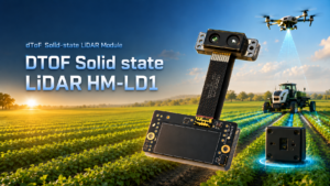
The DTOF Solid State LiDAR HM-LD1 is a compact SPAD dToF-based LiDAR module designed to provide real-time depth images and 3D point cloud data for robotic perception, obstacle avoidance, distance detection, smart inspection, autonomous navigation and robotic vision development. Its compact housing, low weight and multiple interface options make it suitable for embedded development across PCs, Raspberry Pi-class platforms, flight controllers and Linux-based systems. The product page is available at DTOF Solid State LiDAR HM-LD1.
| Product Name | DTOF Solid State LiDAR HM-LD1 |
|---|---|
| Dimension | 43.5 mm × 30 mm × 26.5 mm |
| Ranging Capability | Indoor: 0.5–25 m; Outdoor: 0.2–8 m |
| Ranging Accuracy | ±3 cm |
| Field of View | 60° horizontal × 45° vertical |
| Weight | 28 g |
| Resolution | 40 × 30 |
|---|---|
| Frame Rate | 10 fps |
| Interface | UART / UDP / UVC |
| Operating Temperature | -20 ℃ to 60 ℃ |
| Power Consumption | 1.2 W |
| Supported SDK Platforms | x86 Windows, x86 Linux, ARM Linux |
The HM-LD1 is best suited for applications that need compact real-time depth data rather than a large mechanical scanning unit. Relevant use cases include AMR obstacle detection, UAV altitude hold, terrain following, robot navigation assistance, SLAM support, smart inspection, object detection, volume measurement, zone intrusion monitoring and robotic vision development. Its integration value comes from the combination of compact dimensions, 28 g weight, 1.2 W power consumption, UART / UDP / UVC interfaces, real-time depth maps and 3D point cloud support. Download the DTOF SSL HM-LD1 Product Brochure from the product page for project evaluation and integration planning.
View Product Details & Pricing ➔
Integration Workflow for Developers
Integrating a 3D DTOF LiDAR depth sensor properly takes more than plugging in a cable and reading a stream. The team needs to define the perception objective, validate sensor geometry, choose the right interface, design the mechanical mount, process the depth stream and test the full system under realistic conditions. A structured workflow helps prevent late-stage problems such as blind zones, unstable readings, bandwidth limits, poor alignment or data that does not match the robot’s planning software.
Step 1 — Define the Perception Task
⚙️ Start by naming the exact job the sensor must do. Is it detecting obstacles in front of an AMR, measuring altitude below a UAV, monitoring a security zone, estimating distance to a surface, supporting docking or feeding a SLAM pipeline? Each task has different requirements for range, field of view, update rate and processing. A precise task definition also helps determine whether one sensor is enough or whether the design needs additional sensors for wider coverage or redundancy.
Step 2 — Confirm Range and FOV
⚙️ Validate the indoor and outdoor distances against the robot’s stopping distance, motion speed and safety margin. A mobile robot moving slowly in a controlled indoor environment has very different requirements from a UAV operating outdoors in bright light. The 60° horizontal × 45° vertical field of view should be mapped against expected obstacle locations. Mounting height and pitch angle can dramatically change what the sensor sees, especially near the ground.
Step 3 — Select Interface
⚙️ Choose UART, UDP or UVC based on host architecture and development workflow. UART may fit embedded controllers that need simple serial communication. UDP can work well for networked robotics systems where sensor data is transmitted to a processor over an IP-based link. UVC may simplify camera-style integration and visualization on platforms that already support video input. Developers should check latency, bandwidth, SDK compatibility and operating system support before locking the interface design.
Step 4 — Mount and Align the Sensor
⚙️ Mechanical integration strongly affects perception quality. Consider mounting height, pitch angle, roll alignment, field-of-view obstruction, vibration, cable routing, connector strain and enclosure window material. If the sensor is placed behind a protective window, the material and cleanliness of that window can influence performance. The sensor should be positioned so its field of view covers the area where decisions must be made, while avoiding blind zones created by the robot body, brackets or payloads.
Step 5 — Process Depth Maps or Point Clouds
⚙️ Depth processing often includes thresholding by distance, filtering a region of interest, converting depth data into point clouds, clustering obstacles, rejecting ground returns, generating occupancy information and passing detected objects to a planner. Some teams may use ROS-style or OpenCV-style workflows where applicable, while others may implement lightweight embedded processing. The best pipeline depends on host compute capacity, required latency, robot speed and the complexity of the environment.
Step 6 — Validate in Real Operating Conditions
⚙️ Final validation should include the actual operating conditions, not only a lab bench test. Test indoor lighting, outdoor brightness, reflective surfaces, dark targets, motion, vibration, temperature variation and expected robot speeds. Outdoor applications should include sunlight angles and target materials similar to real deployment. Industrial robotics teams should also evaluate how the sensor behaves when dust, fingerprints, protective covers or mechanical vibration are introduced.
dToF LiDAR vs Other Depth Sensors
Depth sensing technologies overlap, but they are not interchangeable. A 3D DTOF LiDAR depth sensor offers active ranging and spatial distance data in a compact format. Other technologies may offer wider views, richer visual texture, lower cost or different performance tradeoffs. The right choice depends on the application’s range, lighting, environment, compute budget, integration space and accuracy needs. Look, the best sensor is not always the most expensive one. It is the one that gives the robot dependable information in the place where the decision has to be made.
dToF LiDAR vs Single-Point ToF Sensors
✅ Single-point ToF sensors provide one distance reading. They can be useful for proximity detection, simple triggering or basic range measurement. The limitation is obvious once the robot starts moving: one number does not tell the system where an obstacle sits inside the scene. A 3D dToF module provides spatial depth frames, which makes it more useful for obstacle localization, zone detection, ground awareness and local navigation support.
dToF LiDAR vs Stereo Cameras
✅ Stereo cameras estimate depth by comparing image disparity between two lenses. They can provide rich visual information and may be valuable for object recognition, scene understanding and visual SLAM. However, stereo depth can be affected by low-texture surfaces, lighting variation, calibration quality and compute load. dToF LiDAR actively measures distance using emitted light, which can be useful when direct range data is required. In many robots, stereo cameras and dToF sensors work best together rather than competing for the same job.
dToF LiDAR vs Structured Light
✅ Structured light projects a known pattern and observes how the pattern deforms across surfaces. It is often effective at short range indoors, especially for close object scanning or interaction. Outdoor use can be more challenging under strong ambient light. dToF LiDAR is often better suited for robotics scenarios that need short-to-mid-range active distance measurement and outdoor-capable sensing, provided the sensor is validated under the intended lighting and surface conditions.
dToF LiDAR vs Mechanical Spinning LiDAR
✅ Mechanical spinning LiDAR can provide wide or 360-degree scanning and longer mapping coverage. It remains valuable for applications that need panoramic point clouds or long-range localization. Solid-state dToF modules are more compact, lightweight and easier to embed, though they usually cover a more limited field of view. A compact module may replace a spinning LiDAR for forward obstacle detection, altitude feedback or local perception, but panoramic mapping may still require a different sensor architecture.
Deployment Considerations for Industrial Robotics
Commercial deployment requires attention to the full system, not only the sensor specification table. Engineers must consider environmental conditions, sensor fusion, safety architecture, support, supply and customization. A depth sensor can be a powerful perception component, but performance depends on how it is mounted, processed, validated and maintained within the robot platform. In the shop, most sensor problems are not caused by the chip alone. They come from mounting angles, dirty covers, vibration, bad assumptions about lighting or software that was never tested against real objects.
Environmental Conditions
Ambient light, dust, target reflectivity, temperature, vibration and optical contamination can all influence depth sensing. The HM-LD1 lists an operating temperature range of -20 ℃ to 60 ℃, which is important for robots that operate in warehouses, outdoor inspection environments or unconditioned spaces. Teams should test bright sunlight, dark objects, shiny surfaces, angled targets and vibration levels that match real deployment.
Sensor Fusion
A compact dToF LiDAR module can be combined with cameras, IMU, wheel odometry, RTK, GNSS, ultrasonic sensors or mechanical LiDAR depending on autonomy requirements. Sensor fusion allows each technology to compensate for limitations in the others. For example, a camera may provide visual classification, an IMU may provide motion state, wheel odometry may support local movement estimation and dToF depth may provide direct distance structure near the robot.
Safety and Redundancy
Depth sensors can contribute to obstacle awareness, but safety-rated systems may require certified safety sensors, redundant logic and compliance evaluation depending on industry and jurisdiction. Engineers should not assume that a perception sensor alone satisfies functional safety requirements. Instead, use dToF depth data as part of a broader risk-reduction architecture that matches the robot’s application, speed, environment and regulatory obligations.
Supply, Support and Customization
MRP specializes in perception and positioning modules for robots and UAVs, provides technical support for product integration and application, offers direct manufacturing from the source factory and supports customized products on demand. For commercial teams, these factors matter because field deployment often requires more than a datasheet. Support can shorten debugging cycles around sensor mounting, interface selection, outdoor validation and depth data interpretation. For technical support services or custom product requirements, visit MRP Support.
Technical FAQ
Are all ToF sensors considered LiDAR, and what makes a 3D dToF LiDAR depth sensor different?
Can a compact dToF LiDAR replace a traditional spinning LiDAR tower in robots or drones?
What should developers check before choosing a 3D dToF LiDAR depth sensor?
What is the difference between a depth map and a point cloud?
Is 40 × 30 resolution enough for robotics applications?
How does outdoor light affect dToF LiDAR performance?
Which interface should I use: UART, UDP or UVC?
Can dToF LiDAR be used for SLAM?
Why is sensor weight important for drones and mobile robots?
What support matters most for commercial deployment?
📚 References & Further Reading
- Industry Standard: Innoviz Technologies | SOS LAB
- Related Guide: DTOF Solid State LiDAR HM-LD1 | How to Choose Visual RTK Navigation Module | MRP Support






