


Depth Sensor for Drone: How to Choose Lightweight LiDAR for UAV Obstacle Avoidance, Mapping, and Autoflight
Modern drones are not judged only by flight time, camera sharpness, or whether the GPS holds steady on a calm day. Those things matter, of course, but once a UAV starts flying close to people, racks, roofs, walls, trees, machinery, tunnels, bridges, or uneven ground, the real bottleneck is perception. The aircraft has to understand distance in real time while dealing with vibration, sunlight, payload limits, prop wash, wind, reflective surfaces, dark targets, and limited onboard computing power. Here’s the deal: choosing the right depth sensor for drone applications is an engineering decision, not just a shopping-cart decision.
Ultrasonic modules can work for simple short-range altitude hold. Stereo cameras can be powerful, but they often demand more processing, cleaner lighting, and better texture than a small drone can guarantee. Structured-light depth cameras can look great indoors and then lose confidence outdoors under strong sunlight. Lightweight LiDAR, especially compact dToF solid-state LiDAR, gives UAV developers a practical balance of range, power, size, field of view, and integration flexibility. In the shop, that balance is usually what decides whether a prototype becomes a reliable flying system or stays stuck on the bench.
This guide walks through how to evaluate drone depth sensors for obstacle avoidance, mapping, autoflight, altitude hold, terrain following, inspection, and robotics development. It compares LiDAR, depth cameras, ultrasonic sensors, radar, and optical-flow-based sensing from a practical engineering point of view. It also explains how field of view, frame rate, accuracy, range, resolution, interface, weight, power consumption, and mounting choices affect real UAV performance once the propellers are spinning.
As a practical reference, we will use the DTOF Solid State LiDAR HM-LD1, a 28g SPAD dToF LiDAR module with 40×30 resolution, 10fps depth output, ±3cm ranging accuracy, 60°×45° FOV, UART/UDP/UVC interfaces, and outdoor daytime ranging up to 8m. The point is not to pretend one module solves every UAV problem. The point is to show what matters when integrating a lightweight LiDAR module into drones, robots, embedded Linux platforms, flight controllers, and test rigs.
Table of Contents
- 👉 What Is a Depth Sensor for Drone Applications?
- 👉 Why Drones Need Depth Sensing Beyond GPS and Cameras
- 👉 Drone Depth Sensor Types Compared
- 👉 How Lightweight LiDAR Works on UAVs
- 👉 Key Specs for Choosing a Drone Depth Sensor
- 👉 Obstacle Avoidance and Autoflight Design
- 👉 Mapping, Inspection, and Terrain Following with Drone Depth Sensors
- 👉 Integration Workflow with Flight Controllers and Embedded Platforms
- 👉 DTOF Solid State LiDAR HM-LD1 Specifications
- 👉 Selection Checklist for UAV Engineers
- 👉 Choosing the Right Depth Sensor for Drone Development
- 👉 FAQ: Drone Depth Sensors and Lightweight LiDAR
What Is a Depth Sensor for Drone Applications?
A depth sensor for drone applications measures the distance between a UAV and surrounding objects, terrain, walls, floors, ceilings, infrastructure, vegetation, shelves, inspection surfaces, landing zones, or other aircraft. Unlike a standard RGB camera, which captures color and texture, a depth sensor outputs distance information. Depending on the technology, that distance information may be a single-point measurement, a 2D depth image, a matrix of distance values, or a 3D point cloud representing the environment around the drone.
Look, a drone does not avoid a wall because the wall looks like a wall. It avoids the wall because the control system knows how far away that wall is and has enough time to react. A GPS receiver can tell the UAV where it is globally, but it cannot tell the drone that a tree branch is two meters ahead. A barometer can estimate altitude, but it cannot identify a sloped roof, bridge beam, shelf edge, loading dock, curb, or uneven landing surface. A camera can help with object recognition, but software must interpret the image before the aircraft can make a safe motion decision.
Depth sensors are used when a drone must make decisions based on real-world geometry. That includes obstacle avoidance, altitude hold, approach control, terrain following, autonomous landing, docking, SLAM research, low-altitude inspection, and autonomous navigation in GPS-denied environments. The sensor gives the drone a direct measurement of space instead of asking software to infer everything from color, contrast, and image texture.
When engineers discuss drone depth sensors, they are not talking about one single category. The term can include lightweight LiDAR, dToF LiDAR modules, stereo depth cameras, structured-light cameras, indirect ToF cameras, ultrasonic rangefinders, mmWave radar, optical flow modules, and sensor fusion systems. Each option has trade-offs. A racing drone, warehouse inspection drone, mapping UAV, agricultural drone, and indoor robotics platform may all need different sensing architectures.
Depth Data vs. Camera Images
RGB cameras describe how a scene looks. Depth sensors describe how far away the scene is. That difference matters because many UAV safety decisions depend on distance, not appearance. A drone may recognize that an object is a wall, but it still needs to know whether that wall is 0.8m, 3m, or 8m away. Depth data helps define braking distance, safe approach speed, hover position, descent rate, and avoidance direction.
In the shop, this distinction shows up fast. A visual system may see a clean white wall and struggle because there is not enough texture for stereo matching. A LiDAR depth sensor may still return usable distance information because it is measuring reflected light timing rather than comparing image features. For robotics and UAV perception ecosystems, platforms such as RoboBaton can be part of a broader development environment where perception modules, mobility systems, and autonomy workflows are tested together.
Single-Point Range vs. Depth Map vs. Point Cloud
A single-point distance sensor provides one range value. That can be useful for basic altitude hold, simple landing detection, or measuring the distance to one surface directly below the drone. The limitation is obvious: one point cannot describe the shape of the surrounding environment. If the drone is descending toward a pallet edge, cable tray, stair, pipe, or uneven terrain, a single point may miss the risk.
A depth map provides a grid of distance values across a field of view. That is far more useful for detecting obstacles in zones such as left, center, right, upper, and lower. A point cloud represents measured points in 3D space and is useful for mapping, SLAM experiments, inspection, wall following, surface measurement, and robotics development. For many UAV engineers, a compact depth map or point cloud sensor is a practical middle ground between simple rangefinders and heavy high-resolution perception systems.
Why Drones Need Depth Sensing Beyond GPS and Cameras
GPS, IMU, barometer, compass, optical flow, and RGB cameras are valuable parts of a drone navigation stack, but none of them fully replaces direct distance sensing. GPS can localize a drone outdoors, yet it cannot detect a powerline, warehouse rack, bridge beam, tree branch, window frame, tunnel wall, pole, person, or moving vehicle. IMUs estimate motion but drift over time. Barometers estimate altitude but are affected by pressure changes and airflow. RGB cameras depend on lighting, contrast, object recognition, and computing resources. Optical flow can estimate relative motion over textured surfaces but may not provide reliable absolute distance to obstacles in every direction.
A drone depth sensor adds direct range information to the autonomy system. This is especially important when the UAV flies close to objects, operates indoors, approaches infrastructure, follows terrain, performs low-altitude inspection, or navigates in GPS-denied environments. Warehouses, tunnels, bridges, dams, construction sites, forests, industrial plants, solar farms, and docking stations all create scenarios where the drone needs to detect surfaces before contact occurs.
Here’s the deal: GPS can get you to the job site, but it will not keep a propeller out of a beam flange. A camera can show the operator a beautiful image, but the flight controller still needs dependable distance data if the aircraft is expected to slow, stop, climb, descend, or hold a safe standoff. For developers learning how to connect perception modules with robotic systems, the RoboBaton Mini tutorial is a useful internal resource for understanding practical robotics workflows.
Obstacle Avoidance Requires Reaction Distance
Obstacle avoidance is not simply detecting that an object exists. The UAV must detect the object early enough to slow down, stop, climb, descend, or reroute. That means the useful range of a drone distance sensor depends on flight speed, frame rate, processing latency, flight controller response, braking capability, payload weight, wind conditions, and safety margin. A slow indoor inspection drone may use near-range depth data effectively. A fast outdoor UAV needs greater detection distance and faster control response.
For example, a 10fps depth stream delivers ten updates per second. In controlled low-speed flight, this may be sufficient for zone-based obstacle detection, landing assistance, approach control, and embedded perception tasks. In high-speed autonomous flight, engineers must calculate how far the drone travels between frames, how long the algorithm takes to process depth data, and how quickly the aircraft can decelerate. This engineering process is more important than simply choosing the sensor with the most impressive headline range.
Autoflight Needs Stable Environmental Perception
Autoflight functions such as terrain following, autonomous landing, corridor navigation, route inspection, docking, wall following, and structure standoff control require stable environmental perception. A drone inspecting a bridge may need to maintain a fixed distance from a beam. A UAV flying above uneven ground may need to adjust altitude continuously. A warehouse drone may need to identify racks, doors, walls, pallets, forklifts, ceiling structures, and people.
A depth sensor helps provide the geometric awareness needed to support these behaviors. It gives the autonomy stack something practical to work with: distance values that can be filtered, zoned, thresholded, transformed, and converted into motion constraints. When supplier support, integration experience, and UAV perception expertise matter, users can also review the company background at My Robot Project About Us.
Drone Depth Sensor Types Compared
Choosing a UAV depth sensor is a trade-off between range, weight, power, field of view, resolution, processing demand, outdoor performance, cost, and integration complexity. No single technology is perfect for every drone. The best option depends on the mission, flight speed, payload budget, development platform, available compute, and environment. Industrial sensor ecosystems are broad, and suppliers such as domisensor show how diverse the sensing market can be across robotics, automation, and industrial detection.
Lightweight LiDAR and dToF LiDAR
Direct Time-of-Flight LiDAR measures distance by emitting light pulses and measuring the return time. In UAV systems, lightweight solid-state LiDAR can provide direct distance data without relying heavily on image texture. Because solid-state modules avoid large spinning assemblies, they are more suitable for small drones where weight, durability, and mechanical simplicity matter. A dToF LiDAR module may output depth maps and point clouds, making it useful for obstacle avoidance, altitude hold, terrain following, near-range mapping, autonomous navigation, and robotic vision development.
The advantages of dToF LiDAR include direct ranging, practical outdoor potential, lower processing demand than stereo vision in many applications, and compact integration. Limitations include dependence on optical design, target reflectivity, ambient light, field of view, and resolution. In plain terms, LiDAR is strong because it measures distance directly, but it still has to be tested against the materials, lighting, vibration, and flight speeds the drone will actually see.
Stereo Depth Cameras
Stereo depth cameras estimate distance by comparing two images from separated camera lenses. They can produce rich spatial information and may be valuable for visual SLAM, AI navigation, object-aware autonomy, and advanced perception systems. However, stereo vision depends on texture, lighting, calibration, baseline distance, and processing power. Blank walls, repetitive patterns, darkness, glare, and low-contrast surfaces can reduce accuracy.
For small drones, the processing load and thermal demand can become a real design constraint. A powerful companion computer may solve the computation problem, but it also adds weight, heat, power draw, and wiring complexity. Stereo can be the right answer for some UAVs, especially when visual context matters, but it should not be treated as a free upgrade over simpler ranging systems.
Structured-Light and iToF Depth Cameras
Structured-light cameras project a known pattern and analyze deformation to calculate depth. Indirect ToF cameras estimate phase shift to infer distance. These technologies are common in indoor robotics, human interaction systems, and short-range depth cameras. They can provide useful dense depth data indoors, but outdoor sunlight can interfere with infrared projection and detection.
For drone applications, structured-light and iToF cameras are often better suited to controlled environments than bright outdoor inspection missions. They may be excellent for an indoor robot, bench test, or controlled lab flight, but a roof inspection at noon or a solar farm pass under strong sun is a different problem. Always separate indoor specification comfort from outdoor flight reliability.
Ultrasonic Rangefinders
Ultrasonic sensors use sound waves to estimate distance. They are simple, low-cost, and useful for basic landing assistance or short-range altitude detection. However, they have major limitations for advanced UAV obstacle avoidance. Surface angle, soft materials, wind, noise, beam width, and response speed can affect performance. Ultrasonic modules usually do not provide a depth map or point cloud, so they are not ideal when the drone must understand obstacle shape or make directional avoidance decisions.
In the shop, ultrasonic sensors are often useful for early experiments because they are easy to wire and easy to understand. In the field, they can become unpredictable around angled surfaces, fabric, vegetation, turbulent air, and noisy machinery. They still have a place, but they are not a complete perception system for serious autonomous obstacle avoidance.
mmWave Radar
mmWave radar can operate in dust, fog, smoke, and low visibility. It is useful for presence detection, harsh environment sensing, and safety support. However, compact drone radar modules often provide lower spatial resolution than LiDAR or cameras. Radar signal interpretation can also be more complex. For many UAV systems, radar works best as part of a sensor fusion architecture rather than as the only depth perception device.
Radar is especially attractive when optical systems struggle because of environmental conditions. The trade-off is that radar may not give the fine spatial detail needed for near-range shape interpretation, tight navigation, or detailed mapping. A good engineering approach is to decide whether radar is the primary sensor, a backup safety sensor, or one input in a multi-sensor stack.
| Sensor Type | Best Use on Drones | Strengths | Limitations |
|---|---|---|---|
| dToF Solid-State LiDAR | Obstacle avoidance, altitude hold, terrain following, near-range mapping | Direct distance data, compact design, low processing load, outdoor-capable architecture | Resolution and range depend on module design and environment |
| Stereo Depth Camera | Visual SLAM, AI navigation, object-aware perception | Rich visual information and passive sensing | Needs texture, lighting, calibration, and processing power |
| Structured-Light / iToF Camera | Indoor robotics and short-range interaction | Dense depth output and good indoor usability | Often limited outdoors under strong sunlight |
| Ultrasonic Sensor | Basic landing and altitude detection | Low cost and simple output | Limited range, low spatial awareness, and environmental sensitivity |
| mmWave Radar | Harsh environment detection and safety support | Works in dust, fog, and low visibility | Lower spatial resolution for detailed mapping |
How Lightweight LiDAR Works on UAVs
Lightweight LiDAR works by converting reflected light into distance data. In a direct Time-of-Flight system, the sensor emits a light pulse and measures how long it takes for the reflected signal to return. Since the speed of light is known, the sensor can calculate distance from travel time. In a SPAD-based dToF module, highly sensitive single-photon avalanche diode technology helps detect returning photons, supporting compact ranging modules that can generate real-time depth images and 3D point cloud data.
The big advantage for drones is that the output is already distance-oriented. The aircraft does not need to infer every distance from two camera images or from object-recognition software. The sensor provides range measurements that can be passed into filters, obstacle zones, safety thresholds, and navigation logic. That makes LiDAR attractive for embedded systems where power, weight, and computing headroom are limited.
From Distance Pixels to Depth Maps
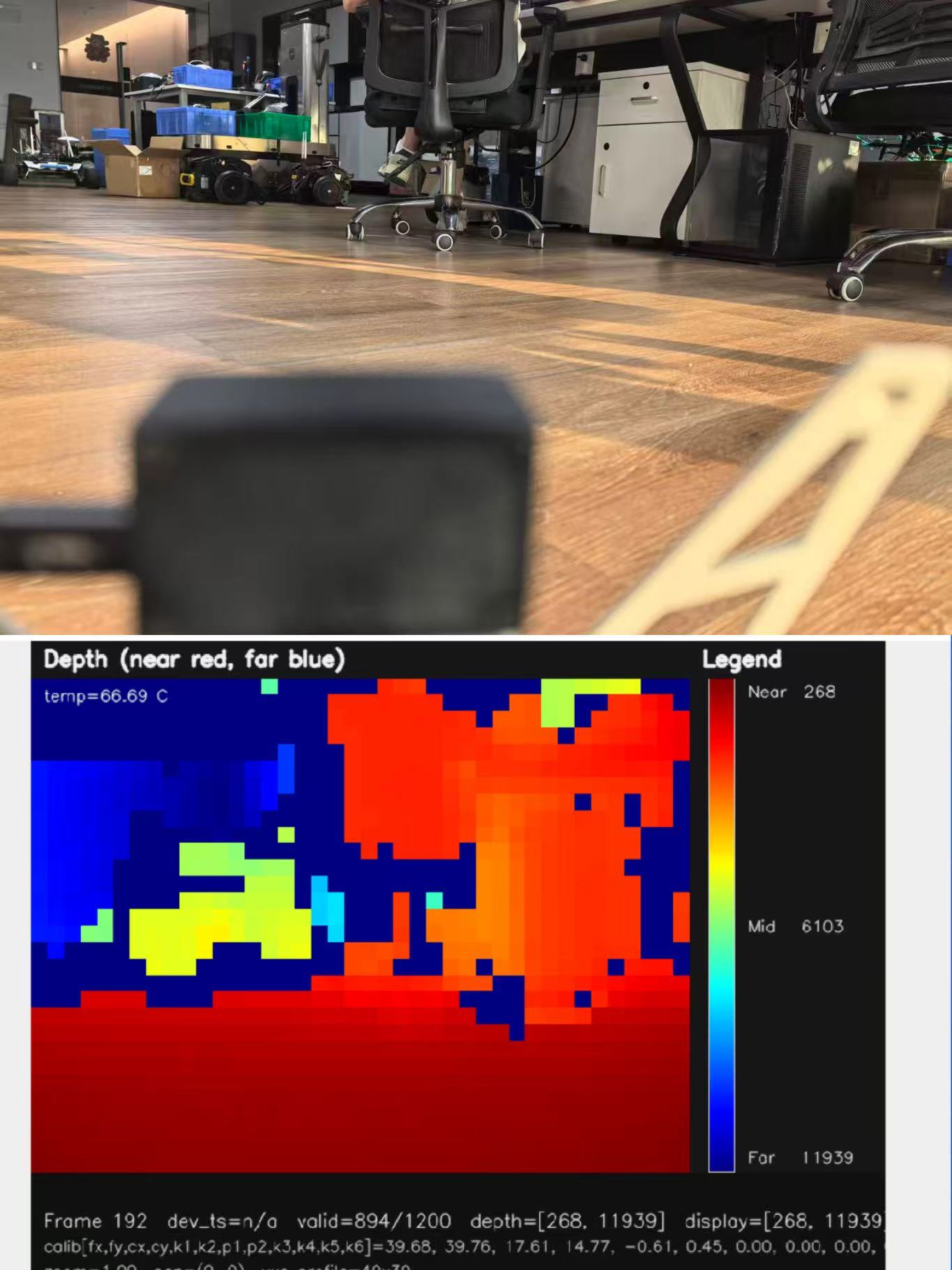
A depth sensor with 40×30 resolution outputs 1,200 distance points per frame. While this is not equivalent to a high-resolution visual image, it can be very useful for UAV decision-making. Many obstacle avoidance tasks do not require detailed texture. They require reliable distance estimates in practical zones. A drone can divide a depth map into regions and decide whether the center path is blocked, whether the lower area is safe for descent, or whether an obstacle is closer on the left or right side.
For example, a forward-facing sensor can divide the scene into left, center, and right channels. A downward-facing sensor can evaluate whether the landing area is flat, sloped, or interrupted by an object. A side-facing sensor can support standoff control during wall or structure inspection. The value is not only the number of pixels. The value is whether the data supports a safe, repeatable control decision.
From Depth Maps to Point Clouds
Depth maps can be converted into point clouds when the field of view and calibration model are known. A point cloud represents measured points in three-dimensional space, allowing developers to perform clustering, ground segmentation, wall detection, object boundary analysis, occupancy grid creation, and SLAM research. For drones, point cloud data is useful in near-range mapping, inspection, autonomous navigation experiments, and robotic perception development.
Point clouds are especially useful during development because they help engineers see what the sensor sees. If a drone reacts late, ignores a dark surface, misreads a shiny object, or struggles with an angled wall, point cloud visualization can expose whether the problem comes from sensing, filtering, coordinate transforms, or control logic. That kind of visibility saves time during debugging.
Why Solid-State Design Matters for Drones
Traditional mechanical LiDAR can provide powerful scanning performance, but it may be heavy, expensive, and mechanically complex for compact UAV platforms. Solid-state LiDAR reduces moving parts and can be easier to mount on small drones. A module weighing 28g is much easier to integrate than a heavier scanning system, especially when the drone also needs batteries, cameras, radios, controllers, protective frames, and mounting hardware.
Low weight helps protect flight time and leaves more payload budget for mission-specific equipment. It also reduces the mechanical burden on the airframe. Less mass hanging off the nose, belly, or side of the drone means less stress during acceleration, braking, landing, and vibration. For compact UAVs, those mechanical details matter just as much as the sensor datasheet.
Key Specs for Choosing a Drone Depth Sensor
The best depth sensor for drone development is not automatically the sensor with the longest advertised range or highest resolution. UAV engineers must evaluate how each specification affects real flight behavior. Weight, power consumption, field of view, frame rate, range, accuracy, interface, operating temperature, data format, SDK support, and mounting all influence whether the sensor can be successfully integrated into an aircraft.
Look at the full system, not just the component. A sensor can look excellent on paper and still be wrong for the drone if it needs too much power, adds too much weight, outputs data in the wrong format, has a field of view that misses the hazard, or cannot handle outdoor lighting. Good UAV sensor selection is about matching the measurement tool to the mission profile.
Weight and Payload Budget
Weight directly affects flight time, thrust margin, stability, battery consumption, and mechanical design. A UAV depth sensor should be evaluated together with cable weight, mounting bracket weight, vibration isolation, protective housing, and companion computer requirements. A lightweight LiDAR module is attractive because it leaves more capacity for batteries, payload cameras, communication modules, and safety hardware.
For compact drones, even small differences in payload weight can noticeably affect endurance and control response. A 28g sensor may be easy to mount on a small UAV where a heavier perception payload would force a larger frame, larger battery, or reduced mission time. The right weight decision often makes the difference between a clean integration and a drone that flies poorly once everything is installed.
Ranging Capability
Range should be evaluated separately for indoor and outdoor conditions. Indoor performance may be stronger because ambient light is lower. Outdoor performance can be affected by sunlight, surface reflectivity, target angle, atmospheric conditions, and sensor optical design. A UAV obstacle avoidance sensor must provide enough range for the drone to react safely.
For low-speed inspection, landing assistance, indoor navigation, and terrain following, near-range performance can be more important than long-range headline specifications. A drone flying slowly through a warehouse may benefit more from stable 0.5m to 8m detection than from a long-range number that only applies under ideal lab conditions. Always ask what range is reliable in the actual mission environment.
Accuracy
Ranging accuracy determines how reliably the drone estimates distance. Accuracy is important for altitude hold, docking, standoff control, terrain following, and inspection. However, system-level accuracy also depends on mounting stability, vibration, calibration, timestamp synchronization, filtering, and coordinate transformation.
A depth sensor may provide accurate raw measurements, but poor mounting or loose calibration can reduce real-world performance. If the sensor is tilted a few degrees from the expected axis, or if vibration changes the sensor angle during flight, the control system may act on distorted distance estimates. That is why good mechanical mounting and calibration are not optional details.
Field of View
Field of view defines angular coverage. A forward-facing sensor with a useful horizontal and vertical FOV can support obstacle detection in the flight path. A downward-facing sensor can support landing and terrain following. A side-facing sensor can support wall following or inspection standoff control. A narrow FOV may miss obstacles outside the detection cone, while an extremely wide FOV may reduce point density.
Engineers must match FOV to drone speed, direction of travel, and mission behavior. If the drone turns quickly, flies sideways, or approaches angled structures, one forward-facing sensor may not be enough. If the mission is mostly landing support, downward coverage may matter more than forward coverage. There is no universal mounting answer; there is only the right answer for the flight behavior.
Resolution
Resolution affects how many distance points are available. Higher resolution can improve object boundary detection and scene interpretation, but it can also increase bandwidth and processing requirements. Lower resolution can be practical for embedded UAV systems when the goal is zone-based detection, not high-detail reconstruction.
A 40×30 depth map can be suitable for obstacle zones, approach control, and perception prototypes when combined with filtering, clustering, and appropriate thresholds. The question is not whether 40×30 looks impressive next to a camera image. The question is whether 1,200 range points per frame are enough to support the control decisions required by the aircraft.
Frame Rate and Latency
Frame rate determines how often the UAV receives updated depth information. Latency determines how quickly that information becomes usable for control. A 10fps stream may be useful for controlled low-speed flight, inspection, landing assistance, and embedded perception. Faster drones require careful calculations.
Engineers should consider the distance traveled between frames, processing delay, communication delay, and flight controller response time before defining safety zones. A drone traveling at 1m/s moves 10cm between 10fps frames before processing and control delay are even considered. At higher speeds, the safety margin must grow. This is where engineering judgment matters more than marketing numbers.
Interface Options
Interfaces determine integration difficulty. UART can be useful for flight controllers or microcontrollers that need compact distance data. UDP can support networked embedded systems and companion computers. UVC can simplify depth stream access by exposing the device in a familiar video-style workflow. A flexible drone depth sensor should support the data path that matches the project architecture.
That architecture might be a flight controller, Raspberry Pi, embedded Linux board, x86 PC, or robotics development system. The interface also affects debugging. A UVC-style workflow may be convenient for visualizing depth on a development computer. UART may be better for a simpler embedded system. UDP may make sense when the sensor and processor communicate over a networked link.
Power Consumption and Operating Temperature
Power consumption affects flight endurance and thermal design. A low-power module is easier to support on small UAV platforms than a high-power perception stack. Operating temperature also matters because drones may fly in cold outdoor environments, hot summer sunlight, industrial buildings, or airflow-cooled conditions.
Engineers should validate sensor behavior across realistic temperature ranges, lighting conditions, vibration levels, and mission durations. A module that works on a bench for five minutes may behave differently after sitting in direct sun, operating near motors, or flying in cold airflow. Power and temperature are not just electrical specifications; they are reliability specifications.
Obstacle Avoidance and Autoflight Design
To use a depth sensor effectively, UAV developers must translate sensor data into flight behavior. A depth map alone does not guarantee obstacle avoidance. The system needs detection zones, filtering, thresholds, control rules, fallback behavior, and safety margins. The drone must know when to continue, slow down, stop, climb, descend, reroute, or reject a path.
Here’s the deal: the sensor is only one part of the safety chain. The aircraft also needs good mounting, clean data handling, a sensible control policy, and enough room to act. A great sensor connected to poorly tuned control logic can still produce a crash. A modest sensor connected to conservative, well-tested logic can deliver useful, dependable safety behavior.
Forward Obstacle Avoidance
A forward-facing LiDAR depth sensor can detect objects in the drone’s flight path. The perception algorithm can divide the depth map into left, center, right, upper, and lower zones. If the center zone contains an obstacle within a defined threshold, the drone may reduce speed or stop. If the left side is blocked and the right side is clear, the navigation system may choose a rightward avoidance command.
This zone-based method is practical for embedded UAV systems because it does not always require heavy object recognition. The drone does not need to know whether the obstacle is a box, wall, pipe, railing, or tree branch before taking a safe action. It only needs to know that the path ahead is not clear within the defined stopping distance.
Downward Altitude Hold and Landing
A downward-facing drone distance sensor can estimate distance to the ground, landing pad, floor, roof, or terrain surface. This can improve low-altitude behavior where barometer and GPS altitude are not precise enough. During landing, depth data can help reduce descent speed as the ground approaches. During hover, it can support more stable height control above uneven surfaces.
For indoor drones, downward depth sensing can be especially useful when GPS is unavailable. It can also help when barometric altitude drifts because of HVAC airflow, prop wash, or pressure changes. The key is to filter the signal carefully and handle invalid readings safely, especially over reflective floors, dark mats, grass, stairs, and cluttered landing zones.
Terrain Following
Terrain following requires the UAV to maintain a target height above uneven ground. A depth map can help detect slopes, sudden elevation changes, and near-field terrain features. This is useful in agriculture, inspection, survey support, and low-altitude autonomy. Terrain following requires careful filtering because grass, reflective surfaces, dust, shadows, and angled terrain may affect measurements.
Flight speed should be matched to sensing range and update rate. A drone flying too fast over rising terrain can run out of reaction distance. A conservative terrain-following design will combine depth sensing with velocity limits, filtered height estimates, and safe fallback behavior if the data becomes uncertain.
Indoor Navigation and GPS-Denied Flight
Indoor drones need perception because GPS is weak or unavailable. A depth sensor can help detect walls, shelves, equipment, people, doorways, and ceiling structures. When combined with optical flow, IMU data, visual odometry, SLAM, or motion capture during development, depth sensing can support safer navigation.
In warehouse or factory applications, the ability to detect near-range obstacles can be more valuable than long-range outdoor mapping capability. Indoor flight often happens close to racks, conveyors, fixtures, columns, and workers. A lightweight LiDAR depth sensor can provide useful geometric awareness without forcing the drone to carry a large perception payload.
Safety Zones and Control Logic
A practical UAV obstacle avoidance system often uses multiple safety zones. A warning zone may reduce speed when an object is detected ahead. A braking zone may command the drone to stop or hover. An emergency zone may trigger climb, reverse, hold, or mission abort behavior depending on the aircraft and environment. These zones should be tuned using real flight tests, not only simulations.
Engineers should validate behavior with different surfaces, lighting conditions, angles, speeds, and vibration levels. The safest systems are usually conservative at first. Start with slow flight, large safety margins, and simple control responses. Then tighten the behavior only after the data proves stable across the expected operating conditions.
Mapping, Inspection, and Terrain Following with Drone Depth Sensors
Drone LiDAR mapping can mean many different things, from professional aerial survey to near-range obstacle mapping. It is important to match the sensor to the mission. A lightweight depth sensor can provide point cloud data for perception research, inspection support, near-range mapping, and environmental awareness. It should not automatically be positioned as a replacement for long-range professional aerial LiDAR mapping systems unless the project requirements match the sensor capabilities.
Look, there is a big difference between building a drone that understands nearby obstacles and building a certified survey platform. Both may involve LiDAR, but the accuracy, range, density, positioning, calibration, and software requirements are different. A compact depth sensor can be extremely useful for perception and inspection without being a survey-grade mapping payload.
Near-Range 3D Mapping
A compact LiDAR depth sensor can support near-range 3D mapping of walls, objects, indoor areas, inspection targets, shelves, machinery, and obstacles. Developers can process point cloud data for clustering, ground estimation, surface detection, and occupancy mapping. For research and prototyping, this can be valuable because the module is easier to integrate than large mapping payloads.
For production mapping, engineers must evaluate range, density, calibration, positioning, and repeatability. If the use case is building a local occupancy map for navigation, a lightweight depth sensor may be a good fit. If the use case is generating engineering-grade topographic deliverables, the system needs a much deeper validation process.
Infrastructure Inspection
Drones inspecting bridges, expressways, dams, tunnels, solar farms, wind turbines, buildings, and industrial equipment often need to fly close to surfaces. A depth sensor helps maintain safe standoff distance and reduce collision risk. For example, when inspecting a bridge wall, the UAV can use depth data to avoid moving too close while still keeping the camera near enough for visual detail.
In tunnels or industrial spaces, depth sensing can help prevent contact with beams, pipes, cables, valves, ducts, railings, or equipment. The best inspection drones do not just collect images; they maintain controlled positioning so those images are usable and the aircraft remains safe. Depth sensing is one of the tools that makes that controlled positioning possible.
Topography and Waterway Surveying
Topographic and waterway surveying require careful sensor selection. Professional topographic LiDAR often needs longer range, high-density point clouds, accurate GNSS/INS integration, timestamp synchronization, calibration, and specialized mapping software. Bathymetric or waterway surveying may require specific wavelengths and optical designs suitable for water surfaces and penetration requirements.
A lightweight drone depth sensor can still be useful for near-range perception, bank monitoring support, obstacle detection, inspection workflows, and robotics R&D, but it should not be described as survey-grade unless the full system has been validated for that purpose. That distinction protects both the buyer and the engineering team. Use the right tool for the job and be clear about the deliverable.
Point Cloud Use in Robotics Development
Point cloud data can be used for clustering, ground segmentation, obstacle maps, occupancy grids, surface measurement, wall following, and SLAM experiments. Developers working with x86 Windows, x86 Linux, or ARM Linux platforms can build perception pipelines that visualize depth maps, filter out noise, define safety zones, or integrate depth data with other sensors.
The value of point cloud output is not only in mapping. It is also in helping the drone understand the nearby environment well enough to move safely. During development, point clouds can help engineers tune thresholds, inspect blind spots, verify field of view, compare mounting angles, and debug why a drone reacted the way it did.
Integration Workflow with Flight Controllers and Embedded Platforms
Integrating a depth sensor into a drone requires more than connecting wires. Engineers must define where the data is processed, how it is synchronized, how it is transformed into the drone body frame, and how it affects control decisions. A simple system may send range values directly to a flight controller. A more advanced system may send depth maps or point clouds to a companion computer, process obstacle zones, and then send velocity or position commands to the flight controller.
In the shop, integration problems usually show up in the gaps between components. The sensor works. The flight controller works. The companion computer works. Then the full system fails because timestamps are inconsistent, coordinate frames are wrong, latency is too high, or the control logic trusts bad data. A good workflow prevents those problems early.
Integration with Flight Controllers
UART output can be suitable when a flight controller or microcontroller needs compact range data or simplified distance measurements. For downward altitude hold, a flight controller may only need a filtered distance value. For forward obstacle avoidance, the flight controller may need zone-based warnings or processed obstacle distances.
Full depth maps are often better handled by a companion computer, especially when the system must perform filtering, clustering, mapping, or multi-sensor fusion. The flight controller should receive clean, actionable commands or constraints rather than raw data it is not designed to process. Keeping responsibilities clear makes the system easier to test and safer to operate.
Integration with Raspberry Pi, Jetson, PC, and Embedded Linux
UDP and UVC interfaces can be useful for developers using Raspberry Pi, Jetson-style embedded systems, x86 Linux computers, or Windows test platforms. UVC can simplify access to depth streams in computer vision workflows because it behaves like a video-class interface. UDP can support network-style data transport for embedded systems. SDK availability reduces development time and helps engineers move from desktop testing to embedded deployment.
A practical development workflow often starts on a PC where visualization and debugging are easy. Once the data path is understood, the pipeline moves to Raspberry Pi, ARM Linux, or another embedded platform. That staged approach reduces risk because engineers can separate sensor evaluation from flight-control testing.
ROS and OpenCV Workflows
Many UAV developers use ROS-style pipelines and OpenCV workflows for perception development. Depth data can be visualized, filtered, segmented, and converted into obstacle zones. ROS can support mapping, navigation experiments, coordinate transforms, and sensor fusion. OpenCV can help with depth image processing, thresholding, region analysis, and visualization.
Unless official compatibility is verified, it is better to describe a sensor as suitable for these workflows rather than claiming certified support. That is the honest engineering position. Developers can still build strong perception pipelines with the right data access, SDK support, and integration effort, but compatibility should be tested on the actual software stack.
Mounting, Calibration, and Environmental Testing
Mounting affects data quality. The sensor should be rigidly mounted, protected from excessive vibration, and aligned with the drone body frame. Calibration should account for pitch angle, yaw angle, height offset, and coordinate transformation. Engineers should test the sensor under indoor lighting, outdoor sunlight, dark surfaces, reflective surfaces, angled surfaces, dust, mist, vibration, and realistic flight speeds.
The goal is not only to confirm that the sensor works. The goal is to confirm that the full drone control system reacts safely and predictably. That means logging data, reviewing false positives, reviewing missed detections, checking latency, testing emergency behavior, and validating performance across the conditions the drone will actually face.
DTOF Solid State LiDAR HM-LD1 Specifications
For UAV developers who need a compact depth sensor for drone obstacle avoidance, distance detection, altitude hold, terrain following, inspection, and embedded perception, the DTOF Solid State LiDAR HM-LD1 is a lightweight SPAD dToF LiDAR module designed to output real-time depth images and 3D point cloud data. It supports multiple interfaces, low power consumption, and SDKs for common development platforms. It is suitable for drones, robots, cameras, and security systems that require compact distance perception and practical integration flexibility.
HM-LD1 is based on solid-state LiDAR technology and supports indoor or nighttime ranging up to 25m and outdoor daytime ranging up to 8m. It can be used for UAV altitude hold, terrain following, distance detection, autonomous navigation, robot obstacle avoidance, SLAM development, autofocus support, user presence detection, object recognition, volume measurement, and zone intrusion monitoring. For teams evaluating the module in detail, the DTOF SSL HM-LD1 Product Brochure provides a downloadable product reference.
| Specification | DTOF Solid State LiDAR HM-LD1 |
|---|---|
| Product Name | DTOF Solid State LiDAR HM-LD1 |
| Technology | SPAD dToF solid-state LiDAR |
| Dimension | 43.5mm × 30mm × 26.5mm |
| Ranging Capability | Indoor: 0.5–25m; Outdoor: 0.2–8m |
| Ranging Accuracy | ±3cm |
| Field of View | 60° horizontal × 45° vertical |
| Weight | 28g |
| Resolution | 40 × 30 |
| Frame Rate | 10fps |
| Interface | UART / UDP / UVC |
| Operating Temperature | -20°C to 60°C |
| Power Consumption | 1.2W |
| SDK Support | x86 Windows, x86 Linux, ARM Linux |
| Typical Applications | UAV obstacle avoidance, altitude hold, terrain following, autonomous navigation, inspection, robot vision, SLAM development, distance detection |
View Product Details & Pricing ➔
Why These Specs Matter for Drones
The 28g weight helps protect flight time and payload capacity. The 1.2W power consumption reduces energy demand compared with heavier perception systems. The 60° horizontal by 45° vertical field of view can support practical forward, downward, or side-facing obstacle zones depending on mounting direction. The 40×30 resolution provides 1,200 depth points per frame, which can be suitable for zone-based obstacle detection, distance control, and embedded perception.
UART, UDP, and UVC interfaces allow integration with flight controllers, Raspberry Pi boards, embedded Linux systems, PCs, and development platforms. That flexibility matters because drone projects do not all use the same architecture. Some teams want a direct link to a controller. Others want to visualize depth on a PC first. Others need to stream data into an embedded perception pipeline. A sensor that supports multiple integration paths reduces development friction.
Best-Fit UAV Scenarios
HM-LD1 is best positioned for DIY drone autoflight prototypes, UAV obstacle avoidance development, indoor navigation, GPS-denied robotics, low-altitude inspection drones, terrain following experiments, distance detection, approach control, robot and drone perception education, and embedded depth-map or point-cloud development.
It is especially attractive where small size, low weight, low power consumption, and flexible interfaces matter more than long-range survey-grade mapping capability. That is an important distinction. If the mission is professional topographic LiDAR mapping, choose a system built and validated for that job. If the mission is compact UAV perception, close-range obstacle detection, embedded autonomy, or inspection standoff control, a lightweight dToF LiDAR module is much easier to justify.
Selection Checklist for UAV Engineers
Before choosing a drone depth sensor, define the aircraft mission and control requirements. A sensor that works well for downward landing assistance may not be enough for forward obstacle avoidance. A sensor suitable for indoor robotics may not be ideal for outdoor sunlight. A high-resolution camera may be unnecessary if the drone only needs zone-based collision prevention. A lightweight dToF LiDAR module may be the best fit when the project needs direct distance data, practical integration, and low payload burden.
Use the following checklist as a practical engineering filter before committing to hardware. It is easier to answer these questions before purchase than to redesign the airframe, wiring, software, and control logic after testing reveals a mismatch.
Technical Checklist
- ⚙️ Define sensing direction: forward, downward, side, rear, or multi-sensor coverage.
- ⚙️ Define required range for indoor, outdoor, near-field, and inspection scenarios.
- ⚙️ Calculate drone speed, stopping distance, control latency, and safety margin.
- ⚙️ Match field of view to the flight direction and obstacle avoidance strategy.
- ⚙️ Choose the required data type: single distance value, depth map, point cloud, or SDK stream.
- ⚙️ Confirm interface requirements such as UART, UVC, UDP, CAN, Ethernet, or custom output.
- ⚙️ Check payload budget including mounts, cables, vibration isolation, and housing.
- ⚙️ Calculate power budget, thermal limits, and companion computer requirements.
- ⚙️ Validate operating temperature, sunlight behavior, reflectivity response, and vibration tolerance.
- ⚙️ Confirm SDK availability for Windows, Linux, ARM Linux, or embedded development platforms.
Common Mistakes to Avoid
Common mistakes include choosing range based only on indoor specifications, ignoring outdoor sunlight performance, underestimating vibration, expecting ultrasonic sensors to solve full 3D obstacle avoidance, choosing high-resolution depth cameras without enough compute, ignoring field of view, forgetting latency, and treating all point cloud output as survey-grade mapping.
Another common mistake is testing the sensor while the drone is stationary and then assuming the same results will hold in flight. Propeller vibration, aircraft pitch, motion blur in companion camera systems, sunlight angle, motor electrical noise, and fast-changing target distance can all affect the system. UAV perception design should be tested with real mission conditions because drone movement, lighting, surfaces, and mounting all affect final performance.
Recommended Decision Path
Start by defining the mission type, such as landing assistance, forward obstacle avoidance, inspection, terrain following, indoor flight, or mapping research. Then define obstacle distance, flight speed, and stopping distance. Choose the sensing direction and field of view. Check payload and power limits. Select an interface that matches the flight controller or companion computer. Validate the sensor indoors and outdoors.
After that, tune filtering, control thresholds, safety zones, and emergency behaviors using real flight tests. Start slow and conservative. Log the data. Review what the drone saw before each response. Adjust thresholds based on evidence, not guesswork. That is how a depth sensor becomes part of a dependable UAV autonomy stack.
Choosing the Right Depth Sensor for Drone Development
The right depth sensor for drone development depends on the mission, not only maximum range or resolution. UAV engineers should balance weight, field of view, outdoor performance, power consumption, frame rate, interface, data format, SDK support, and integration complexity. LiDAR is especially useful when a drone needs direct distance information with lower processing overhead than vision-only systems.
Stereo cameras, structured-light cameras, ultrasonic sensors, radar, and optical flow all have roles, but lightweight dToF LiDAR is often a practical choice for compact UAV obstacle avoidance and embedded perception. Here’s the deal: a good drone sensor is not the one with the flashiest spec sheet. It is the one that fits the airframe, supports the mission, survives the environment, and gives the control system reliable information in time to act.
For developers building lightweight UAV obstacle avoidance, altitude hold, terrain following, inspection, and autonomous navigation systems, the DTOF Solid State LiDAR HM-LD1 offers a compact 28g design, 40×30 depth output, 10fps frame rate, ±3cm ranging accuracy, 60°×45° field of view, UART/UDP/UVC interfaces, 1.2W power consumption, and SDK support for x86 Windows, x86 Linux, and ARM Linux. Visit the HM-LD1 product page or download the product brochure to evaluate whether it fits your UAV integration requirements.
FAQ: Drone Depth Sensors and Lightweight LiDAR
Is a low-resolution LiDAR depth sensor good enough for drones compared with a depth camera?
What depth sensor should I choose for DIY drone autoflight and distance sensing?
Can a drone depth sensor be used for 3D mapping, topography, or waterway surveying?
Is LiDAR better than ultrasonic sensing for drone obstacle avoidance?
How much range does a drone obstacle avoidance sensor need?
Can one depth sensor cover all directions on a drone?
What interface is best for integrating a depth sensor with a drone?
Does a drone LiDAR depth sensor work outdoors in sunlight?
📚 References & Further Reading
- Industry Standard: LiDAR technology overview
- Related Guide: RoboBaton Mini tutorial for robotics development workflows






