


Modern UAVs are not judged only by flight time, payload capacity, or camera resolution anymore. Look, those numbers still matter, but in real industrial work they do not tell the whole story. For inspection, mapping, security patrol, warehouse inventory, agriculture, and autonomous robotics, a drone’s ability to spot trouble before it reaches the propellers can decide whether the job gets finished or ends with broken carbon fiber on the floor. A reliable drone obstacle sensing sensor gives the aircraft a real-time feel for distance, direction, and environmental risk before the pilot, autopilot, or onboard computer can react visually. That matters when the drone is flying near bridges, towers, trees, power lines, warehouse racks, reflective surfaces, tight aisles, or GPS-denied indoor areas.
Here’s the deal: choosing the right obstacle sensing module is not as simple as picking the sensor with the longest range on a datasheet. LiDAR, dToF sensors, stereo cameras, structured light, ultrasonic sensors, radar, and optical flow modules all behave differently under sunlight, dust, vibration, low texture, reflective targets, limited payload capacity, and tight power budgets. This guide explains how drone obstacle sensing works, compares LiDAR and depth vision technologies, and shows how to evaluate range, FOV, resolution, weight, power, interface, SDK support, and integration complexity. It also includes a real-world solid-state LiDAR example, the DTOF Solid State LiDAR HM-LD1, so engineers, UAV developers, and purchasing teams can make a better decision for industrial drone projects.
Table of Contents
- 👉 What Is a Drone Obstacle Sensing Sensor?
- 👉 Why Obstacle Sensing Matters for Industrial UAVs
- 👉 How Drone Obstacle Sensing Works
- 👉 Main Types of Drone Obstacle Avoidance Sensors
- 👉 LiDAR vs Depth Vision vs Ultrasonic vs Radar
- 👉 How to Choose the Right Drone Obstacle Sensing Sensor
- 👉 Real Product Example: DTOF Solid State LiDAR HM-LD1
- 👉 Integration Guide for UAV Platforms
- 👉 Industrial UAV Application Scenarios
- 👉 Common Selection and Integration Mistakes
- 👉 Drone Obstacle Sensing Sensor FAQ
- 👉 Choosing a Drone Obstacle Sensing Sensor for Your UAV Project
What Is a Drone Obstacle Sensing Sensor?
A drone obstacle sensing sensor is a perception module that detects nearby objects and sends distance, depth, or environmental information to the flight controller, companion computer, onboard autonomy software, or operator warning system. Depending on the technology, the output may be a single distance value, a two-dimensional depth map, a three-dimensional point cloud, object presence data, confidence values, or a stream that can be processed by robotics software. In plain shop language, the sensor tells the drone what is close, where it is, and whether it is getting too close too fast.
Sharing a compact dToF sensor we’ve been working with for drone obstacle av…
In practical UAV engineering, obstacle sensing supports collision warning, obstacle avoidance, altitude hold, terrain following, docking, landing assistance, indoor navigation, inspection standoff control, and autonomous route planning. A bridge inspection drone may use a forward-facing sensor to hold distance from concrete beams. A warehouse drone may use depth sensing to avoid shelves and forklifts. A terrain-following agricultural drone may use downward sensing to maintain a safer height over uneven ground. The job changes, but the basic requirement stays the same: the aircraft needs dependable range data while it is moving.
Obstacle Sensing vs Obstacle Avoidance
Obstacle sensing and obstacle avoidance are related, but they are not the same thing. Obstacle sensing is the measurement function. It tells the system that an object exists at a certain distance, direction, or depth region. Obstacle avoidance is the control response. It decides whether the UAV should slow down, stop, hover, reroute, climb, descend, or warn the pilot. A sensor can detect a wall, pole, wire, shelf, or tree branch, but the drone still needs decision logic, flight-control integration, safe thresholds, and enough vehicle authority to react in time.
This distinction matters when selecting hardware. A product marketed as an anti-collision module may include embedded processing, while a raw sensor may require the engineering team to write filtering, interpretation, and control software. Advanced UAV systems often combine perception, mapping, localization, path planning, IMU data, GNSS data, and flight controller feedback. The sensor is the foundation, but reliable avoidance depends on the whole system architecture.
What Data Does the Sensor Output?
Different sensors output different data. A simple ultrasonic module may output one distance value. A dToF LiDAR depth sensor may output a depth image and point cloud. A radar module may provide object range and velocity. A camera-based system may provide depth, object classification, or tracking information after processing. Interface options also vary widely, including UART, USB, Ethernet, UDP, UVC, CAN, or vendor SDK APIs.
For UAV, robotics, and industrial perception use cases, see more sensor application examples on the Applications page.
Why Obstacle Sensing Matters for Industrial UAVs
Industrial drones often operate in environments where manual visual piloting is not good enough. In bridge inspection, a UAV may fly near steel beams, concrete columns, cables, water surfaces, and irregular structures. In warehouse inspection, GPS is unavailable, lighting can change quickly, and aisles may contain moving forklifts, pallets, racks, and stacked goods. In agriculture, trees, branches, irrigation equipment, dust, and uneven terrain create dynamic obstacle risks. In telecom and powerline inspection, thin cables may be difficult for cameras or human pilots to detect quickly.
A properly selected drone obstacle sensing sensor reduces collision probability, improves pilot confidence, supports semi-autonomous flight, and allows more repeatable missions. For enterprise users, the benefit is not only safety. Better sensing can reduce downtime, repair cost, payload loss, insurance risk, failed inspections, and operator fatigue. For engineers, obstacle sensing also creates a measurable input for autonomy development, logging, threshold tuning, and mission repeatability.
Industrial Risks Reduced by Obstacle Sensing
Obstacle sensing helps reduce collision with infrastructure, damage to expensive payloads, loss of inspection data, pilot workload, indoor navigation failure, and mission aborts caused by poor visibility. In inspection work, the drone often needs to fly close enough to capture detailed images but far enough to avoid impact. Depth or LiDAR sensing can help maintain a safer standoff distance, especially when visual perception is affected by glare, shadows, vibration, or complex backgrounds.
In the shop, this is where theory meets repair bills. A small obstacle detection mistake can damage a gimbal, crack a frame, destroy a sensor payload, or interrupt a paid inspection job. The more expensive the payload and the tighter the flight path, the more valuable dependable obstacle sensing becomes.
Why Consumer-Grade Avoidance Is Not Always Enough
Consumer drones often include built-in obstacle sensing, but industrial UAVs may require custom sensor placement, longer reliable range, rugged operating temperature, industrial interfaces, SDK access, and compatibility with custom flight stacks. A commercial inspection platform may need a downward module for terrain following, a forward module for structure approach, and a companion computer for point-cloud processing. Consumer systems are optimized for general use, while industrial systems are usually engineered around a specific mission profile.
How Drone Obstacle Sensing Works
Drone obstacle sensing follows a practical pipeline: emission or passive observation, signal capture, distance calculation, filtering, coordinate transformation, risk-zone evaluation, and control response. A LiDAR or dToF module emits light and measures return timing. A stereo camera estimates depth by comparing the disparity between two images. An ultrasonic module uses sound reflection. A radar sensor emits radio waves and analyzes reflections. The autopilot or companion computer then interprets the data to determine whether an object is inside a predefined danger zone.
For UAVs, sensing must happen quickly enough to match aircraft speed. A slow sensor may detect an obstacle, but the drone may not have enough time to brake, hover, or reroute. That is why frame rate, latency, field of view, processing load, confidence filtering, and detection reliability are as important as maximum range. A datasheet number alone does not prove flight safety; the entire control loop must be evaluated under real conditions.
Detection Zone and Field of View
Field of view defines how much of the environment the sensor can observe. A narrow FOV sensor can be useful for focused forward range detection, while a wider FOV covers more area and can detect obstacles entering from an angle. Downward FOV supports altitude hold, landing assistance, and terrain following. Multi-sensor layouts can cover front, rear, sides, and bottom, but every added sensor increases weight, wiring complexity, processing demand, and calibration work.
Range, Accuracy, and Latency
Maximum range is not the same as reliable range. A sensor may perform differently indoors, outdoors, in bright sunlight, on dark surfaces, on reflective materials, or at steep target angles. Accuracy determines how confidently the system can estimate distance. Latency determines reaction time. Frame rate affects moving-object detection and the smoothness of depth updates. Engineers should evaluate all of these values together instead of choosing a sensor based only on the longest published range.
Depth Map and Point Cloud Processing
A depth map is a pixel-like matrix where each value represents distance. A point cloud is a three-dimensional representation of detected surfaces. These outputs are useful for mapping, SLAM support, obstacle segmentation, navigation, and visualization. Companion computers may process the data using ROS, ROS2, vendor SDKs, or custom software. For drones, the processing system must also transform the sensor coordinate frame into the drone body frame so the control logic understands where the obstacle is relative to the aircraft.
Main Types of Drone Obstacle Avoidance Sensors
There is no universal best obstacle sensor for every UAV. The right choice depends on flight speed, payload limit, lighting conditions, required range, software platform, safety objective, and budget. Here are the common technologies engineers usually evaluate for drone obstacle sensing and anti-collision development.
1. dToF LiDAR Sensors
A direct time-of-flight LiDAR measures distance by emitting short light pulses and calculating how long reflected light takes to return. Solid-state dToF modules are attractive for drones because they can provide real-time depth data without mechanical scanning components. They are compact, power-efficient, and suitable for forward obstacle detection, altitude support, mapping assistance, robotic vision, and industrial inspection.
dToF sensors can work well indoors, at night, and in controlled outdoor environments, but performance still depends on sunlight intensity, target reflectivity, optics, algorithms, and installation angle. For UAV engineers, the key advantage is direct distance measurement with relatively straightforward integration compared with heavier vision-only perception systems.
2. 3D Solid-State LiDAR Modules
Solid-state LiDAR can output depth maps and point clouds without a spinning assembly. That improves durability and simplifies integration into compact UAV platforms. It is useful where weight, vibration resistance, and mechanical reliability matter. Solid-state modules can be mounted forward, downward, or at an angle depending on the mission. They are often selected for compact drones, AMRs, mobile robots, embedded vision platforms, and inspection devices.
For broader industrial LiDAR context, readers can compare established LiDAR manufacturers such as HOKUYO and emerging solid-state LiDAR companies such as Blickfeld.
3. Stereo Depth Cameras
Stereo cameras use two lenses to estimate depth from image disparity. They can provide dense depth data and rich visual information, which makes them useful for AI vision, object recognition, tracking, and scene understanding. However, they need texture, lighting, calibration, and processing power. They may struggle with blank walls, transparent surfaces, darkness, glare, and fast motion if exposure or compute performance is limited.
4. Structured Light Sensors
Structured light sensors project a known pattern and observe distortion to calculate depth. This approach can work well at short range indoors, especially in controlled lighting. For outdoor UAV obstacle sensing, structured light is often less suitable because sunlight can interfere with the projected pattern. It may still be useful for indoor robots, docking stations, close-range measurement, and controlled factory environments.
5. Ultrasonic Sensors
Ultrasonic sensors are low-cost and simple. They are common for short-range altitude hold, landing assistance, or basic proximity warning. However, they usually have lower resolution, wider uncertainty, slower response, and poor performance on soft, angled, narrow, or irregular surfaces. They are best treated as basic range aids rather than complete obstacle perception systems.
6. Millimeter-Wave Radar
Radar is strong in fog, dust, smoke, darkness, and other low-visibility environments. It detects objects based on radio wave reflections and is less affected by lighting than cameras or optical sensors. However, small-object resolution and precise 3D mapping may be limited compared with LiDAR or depth cameras. Radar is valuable for harsh industrial safety, velocity detection, and all-weather sensing, especially when fused with other sensors.
LiDAR vs Depth Vision vs Ultrasonic vs Radar
The best drone obstacle sensing sensor depends on the mission. LiDAR is often preferred for direct distance and depth measurement. Depth cameras are preferred when visual context and AI recognition matter. Ultrasonic sensors are useful for simple low-cost proximity tasks. Radar is attractive for poor weather or low-visibility environments. The table below summarizes the tradeoffs for UAV selection.
| Sensor Type | Best For | Strengths | Limitations | Typical UAV Use |
|---|---|---|---|---|
| dToF / Solid-State LiDAR | Accurate range and depth sensing | Real-time distance, compact design, depth map, point cloud support | Outdoor range depends on sunlight and target reflectivity | Forward obstacle detection, terrain following, inspection, navigation |
| Stereo Depth Camera | Visual perception and dense depth | Rich image data, object recognition potential, passive sensing | Requires texture, lighting, calibration, and compute | Autonomous flight, AI vision, indoor navigation |
| Ultrasonic | Low-cost short-range detection | Simple, inexpensive, low processing demand | Short range, low resolution, surface-dependent | Landing assist, altitude hold, basic proximity warning |
| Millimeter-Wave Radar | Harsh weather or low visibility | Works in dust, fog, smoke, and darkness | Lower spatial detail than LiDAR or cameras | Industrial safety, all-weather sensing, velocity detection |
When LiDAR Is the Better Choice
LiDAR is often the better choice when the application needs direct distance measurement, compact integration, better low-light performance, or real-time depth data. It is especially useful for front-facing obstacle detection, maintaining inspection standoff distance, terrain following, docking assistance, and robotic navigation. Solid-state LiDAR is also attractive when vibration and mechanical durability are important.
When Depth Vision Is the Better Choice
Depth vision is often better when AI recognition, object classification, visual tracking, or scene understanding matters more than direct range accuracy. A camera-based system can identify a pallet, doorway, person, vehicle, or landing target when paired with the right software. However, it usually requires more compute and careful handling of lighting, exposure, texture, and calibration.
When to Combine Multiple Sensors
Many advanced drones use sensor fusion. A UAV may use LiDAR for distance, camera vision for object recognition, IMU data for motion estimation, GNSS for outdoor positioning, optical flow for indoor stabilization, and radar for harsh environments. If the UAV also needs positioning hardware, consider a GNSS component such as the GNSS Antenna Module HM-G51B.
How to Choose the Right Drone Obstacle Sensing Sensor
Choosing a drone obstacle sensing sensor is an engineering decision, not only a purchasing decision. The same sensor can perform well in one drone and poorly in another if the flight speed, mounting position, lighting, software integration, or control response is different. Before comparing models, define the mission environment, obstacle type, required sensing direction, payload limit, power budget, output data, and software platform.
Use this checklist before locking in a sensor:
- ✅ Confirm the real mission environment, including indoor, outdoor, high-lux, dusty, reflective, or low-light conditions.
- ✅ Match sensing range to aircraft speed, stopping distance, and control latency.
- ✅ Check weight, size, and power draw against the UAV’s payload and battery budget.
- ✅ Verify that the interface works with the flight controller, companion computer, or development platform.
- ✅ Test the sensor with the actual materials, angles, vibration, and lighting found in the field.
1. Ranging Distance
The required range depends on flight speed, braking distance, payload, mission type, and control latency. A slow indoor drone may only need 0.2–5m of reliable detection. An industrial inspection UAV may benefit from 5–15m when flying near bridges, towers, or large equipment. A fast outdoor autonomous UAV may need longer range or multi-sensor fusion. Engineers should compare indoor range, outdoor daytime range, and real target performance rather than relying on one maximum specification.
2. Accuracy and Repeatability
Accuracy affects how precisely the UAV understands distance. A sensor with ±3cm accuracy can support more confident near-object flight than a low-resolution proximity detector, especially for inspection, docking, and terrain following. Repeatability is also important because unstable readings can trigger false braking, oscillation, or poor control behavior.
3. Field of View
Horizontal and vertical FOV define the sensing window. A wider FOV covers more of the drone’s path but may reduce detail per angle depending on resolution. A 60° horizontal by 45° vertical FOV is useful for many front-facing obstacle detection and near-field depth awareness tasks. For omnidirectional sensing, multiple modules may be needed.
4. Resolution
Resolution determines how much spatial detail the sensor can output. A single-point rangefinder only reports one distance. A 40 × 30 depth sensor produces a matrix of distance values, enabling basic shape awareness, obstacle segmentation, and point cloud visualization. Higher resolution can improve perception but may increase bandwidth, processing, cost, and power demand.
5. Frame Rate
Frame rate affects responsiveness. A 10fps depth stream may be suitable for slow to moderate UAV movements, inspection, robotic navigation, and testing, but high-speed flight may require higher frame rates, longer range, faster control response, or multiple sensing layers. Always evaluate frame rate together with aircraft speed and braking behavior.
6. Weight and Size
Every gram affects battery life, flight time, vibration behavior, and payload margin. A lightweight module around 28g is attractive for compact UAVs and robots where a heavier 3D sensor may reduce endurance. Size matters as well because the module must fit into the airframe without blocking cameras, propellers, landing gear, airflow, or the sensor’s own field of view.
7. Power Consumption
Low power matters because UAVs operate from limited battery capacity. A sensor using about 1.2W is easier to integrate than high-power perception systems, especially on small drones. Engineers should also consider voltage compatibility, current margin, power filtering, heat, and whether the sensor shares power with noisy motors or communication equipment.
8. Interface and SDK Support
UART is useful for embedded controllers and simple serial integration. UDP is useful for networked systems, companion computers, and higher-bandwidth data transfer. UVC is useful for PC-style video or depth stream access. SDK support for x86 Windows, x86 Linux, and ARM Linux is valuable because UAV developers often work with PCs, Raspberry Pi, Jetson-style systems, industrial computers, or embedded Linux platforms.
9. Environmental Conditions
Outdoor sunlight, reflective materials, dark surfaces, rain, fog, dust, operating temperature, vibration, and mounting angle all affect sensing performance. Indoor or nighttime range can be much longer than outdoor daytime range. A buyer should ask whether the published data reflects realistic conditions for the intended mission, especially if the drone will fly under high lux, near water, around metal, or in dusty outdoor environments.
10. Software Compatibility
The sensor must match the flight stack and software workflow. Consider whether it can connect to PX4, ArduPilot, ROS, ROS2, a vendor SDK, a companion computer, or a custom autonomy system. Even when hardware is excellent, integration can fail if data formats, latency, coordinate frames, or driver support do not match the development platform.
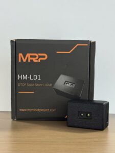
Real Product Example: DTOF Solid State LiDAR HM-LD1
The DTOF Solid State LiDAR HM-LD1 is a compact 3D sensing module based on SPAD dToF technology. It provides real-time depth images and 3D point cloud data for obstacle avoidance, distance detection, autonomous navigation, smart inspection, and robotic vision development. For UAV use, its small size, 28g weight, low power consumption, and UART/UDP/UVC interfaces make it suitable for prototyping and embedded deployment.
View the full product page here: DTOF Solid State LiDAR HM-LD1.
| Specification | DTOF Solid State LiDAR HM-LD1 | Why It Matters for Drone Obstacle Sensing |
|---|---|---|
| Technology | SPAD dToF solid-state LiDAR | Provides direct distance measurement, depth imaging, and 3D perception without mechanical scanning parts. |
| Dimensions | 43.5mm × 30mm × 26.5mm | Compact size helps integration into small UAV frames, inspection drones, and embedded robotic platforms. |
| Weight | 28g | Low weight helps reduce flight-time impact compared with heavier perception systems. |
| Indoor Ranging Capability | 0.5–25m | Suitable for indoor navigation, warehouse inspection, robotics, and nighttime operations. |
| Outdoor Ranging Capability | 0.2–8m | Useful for outdoor daytime obstacle detection, inspection, and near-field UAV safety. |
| Ranging Accuracy | ±3cm | Supports precise distance estimation for obstacle avoidance, terrain following, and close-range inspection. |
| Field of View | 60° horizontal × 45° vertical | Provides a practical forward-facing detection window for UAV anti-collision layouts. |
| Resolution | 40 × 30 | Outputs a depth matrix rather than only a single distance point, enabling basic spatial awareness. |
| Frame Rate | 10fps | Provides real-time sensing for slow to moderate UAV motion, robotics, and inspection tasks. |
| Interfaces | UART / UDP / UVC | Supports integration with flight controllers, PCs, Raspberry Pi, embedded systems, and development platforms. |
| Operating Temperature | -20℃ to 60℃ | Supports industrial and outdoor deployment across common operating environments. |
| Power Consumption | 1.2W | Low power consumption is important for battery-powered UAVs and mobile robots. |
| Development Support | SDKs for x86 Windows, x86 Linux, and ARM Linux | Helps engineers develop on PCs, Raspberry Pi, embedded Linux, and industrial computing platforms. |
Download the DTOF SSL HM-LD1 Product Brochure
View Product Details & Pricing ➔
Why HM-LD1 Fits UAV Obstacle Sensing Projects
HM-LD1 fits UAV obstacle sensing projects because it combines compact mechanical design with real-time depth output. The module weighs 28g, which helps reduce flight-time impact on compact UAVs. Its indoor ranging capability of 0.5–25m supports warehouse, robotics, and nighttime applications, while its outdoor daytime range of 0.2–8m is useful for controlled-speed inspection and near-field safety. The 60° × 45° FOV gives a practical detection window, and the 40 × 30 resolution provides more spatial awareness than a single-point distance sensor.
From an integration perspective, UART, UDP, and UVC interfaces give engineers multiple development paths. UART can support embedded communication, UDP can support networked depth or point-cloud workflows, and UVC can support camera-style access on compatible platforms. SDKs for x86 Windows, x86 Linux, and ARM Linux make the module practical for PCs, Raspberry Pi-class systems, embedded Linux devices, and industrial computing platforms.
Best-Fit Applications for HM-LD1
Best-fit applications include forward obstacle detection, UAV altitude hold, terrain following, smart inspection, robotic vision development, indoor navigation, SLAM support, zone intrusion monitoring, object detection, and volume measurement. It can also be used beyond drones in AMRs, security systems, embedded cameras, robotics testbeds, and perception development platforms where compact 3D sensing is needed.
Integration Guide for UAV Platforms
Successful integration requires more than attaching a sensor to the airframe. Engineers must consider mounting position, vibration, optics, wiring, power quality, data bandwidth, software parsing, coordinate frames, and safety behavior. A good drone obstacle sensing sensor should be tested first on the bench, then on the mounted UAV, then in controlled flight before it is trusted for autonomous behavior.
In the shop, a clean integration workflow usually looks like this:
- ⚙️ Bench-test the sensor with known distances before it ever touches the aircraft.
- ⚙️ Verify power stability, communication, SDK access, and data output under controlled conditions.
- ⚙️ Mount the sensor where the field of view is clear and the aircraft structure does not interfere.
- ⚙️ Run motor-on tests to check vibration, electrical noise, and data stability.
- ⚙️ Perform slow approach testing before enabling any automatic avoidance behavior.
Mechanical Mounting
For forward obstacle detection, the sensor should be placed where it has a clear view of the flight path. For altitude and terrain following, a downward-facing position may be better. The optical window should not be blocked by propellers, landing gear, camera gimbals, payloads, or protective frames. Vibration isolation may be needed because UAV motors can introduce noise into depth data. The mounting angle should match the intended detection zone, and the housing should protect the optical window from dust, scratches, and impact without blocking the field of view.
Electrical Integration
Electrical integration should begin with voltage and power budget verification. The system must provide enough current margin, shared ground where required, clean wiring, and stable power under motor load. UAV environments can be electrically noisy, so power filtering and careful cable routing may be important. Engineers should avoid routing sensor data cables directly beside high-current motor wires when possible and should confirm that communication remains stable during throttle changes.
Data Interface Selection
UART is suitable for simple distance data, configuration, or embedded communication. UDP is better when a companion computer needs network-based depth or point-cloud transfer. UVC is useful for plug-and-play imaging workflows, visualization, and PC-style development. Interface choice should match bandwidth, latency, cable length, software support, and the computing platform. A sensor with multiple interfaces gives engineers flexibility during prototyping and deployment.
Software and Flight Stack Integration
Software integration includes driver setup, SDK testing, data parsing, filtering, coordinate transformation, obstacle zone definition, and failsafe design. If the sensor is mounted off-center or angled, the software must map sensor coordinates to the drone body frame. False positives and missed detections should be logged and reviewed. For advanced systems, a companion computer may process depth maps or point clouds before sending simplified obstacle information to the flight controller.
Testing and Calibration Workflow
Testing should start with known distances on a bench. After basic communication is verified, engineers should test cardboard, metal, concrete, dark surfaces, reflective surfaces, and angled targets. The next step is mounted testing with motors running to evaluate vibration and electrical noise. Indoor slow approach tests should come before outdoor flights. Outdoor testing should include sunlight, shadows, and realistic obstacle shapes. Logs should be reviewed for latency, stability, false positives, and threshold behavior.
Industrial UAV Application Scenarios
Drone obstacle sensing is valuable across many industrial sectors. The same core technology can support infrastructure inspection, indoor logistics, agricultural flight, security patrol, and robotics development. The key is to match the sensor to the environment and control objective.
Bridge, Dam, and Infrastructure Inspection
Infrastructure inspection drones often fly near concrete, steel, beams, cables, and water surfaces. Obstacle sensing helps maintain standoff distance and avoid collision during close inspection. It can also support repeatable approach behavior, which improves data quality across multiple inspection missions. When a drone needs to capture cracks, corrosion, spalling, or structural details, controlled distance is just as important as camera quality.
Warehouse and Indoor Navigation
Warehouses are GPS-denied environments with narrow aisles, racks, changing lighting, reflective packaging, and moving equipment. Depth sensing helps indoor drones detect shelves, walls, pallets, and forklifts. It can also support docking, inventory scanning routes, and controlled flight around storage infrastructure. In this type of environment, predictable near-field sensing is often more valuable than extreme long-range detection.
Powerline and Telecom Inspection
Powerline and telecom inspection involve thin obstacles, towers, cables, and complex geometry. Visual-only navigation can be difficult because wires may blend into the background. Obstacle sensing adds a distance-based layer that can help the UAV maintain safer spacing around infrastructure. Engineers should still be careful here, because thin wires are difficult targets for many sensing technologies and may require sensor fusion, slower flight, or specialized detection methods.
Agriculture and Orchard Flying
Agricultural drones may encounter branches, canopy variation, uneven terrain, irrigation equipment, dust, and changing sunlight. A downward or forward sensing module can support terrain following, crop monitoring, and obstacle warning. In orchards, sensing is especially useful because branches and trunks create irregular near-field hazards. Dust, vibration, and changing target reflectivity should be part of the test plan before field deployment.
Security Patrol and Zone Intrusion Monitoring
Depth sensing can support presence detection, object detection, and zone intrusion monitoring. A UAV or fixed robotic platform can use depth data to identify movement or object presence in a monitored area. This is useful for industrial yards, warehouses, perimeter patrols, and restricted zones. When paired with cameras or other perception tools, depth sensing can help reduce false alarms by adding distance and shape information.
Robotics and Multi-Platform Development
The same sensing technologies used in UAVs can also be applied to AMRs, mobile robots, cameras, and embedded vision platforms. Engineers developing drone perception can often reuse depth-processing concepts in ground robots and inspection systems. For more UAV and robotic perception scenarios, visit the Applications page.
Common Selection and Integration Mistakes
Many obstacle sensing problems come from mismatched expectations rather than defective hardware. A sensor can be excellent in the right environment and insufficient in the wrong one. Avoiding the following mistakes can save engineering time, reduce crashes, and improve deployment reliability.
Mistake 1: Choosing Maximum Range Without Checking Real Outdoor Range
Indoor and outdoor range can differ significantly due to sunlight, reflectivity, and environmental noise. A sensor that performs well indoors may have shorter range outdoors under high lux. Always evaluate range in the actual mission environment.
Mistake 2: Ignoring Sensor Weight
Heavier sensors reduce payload margin and flight time. They can also change center of gravity and affect vibration. For compact UAVs, a lightweight solid-state module may be more practical than a larger perception system.
Mistake 3: Confusing Detection With Avoidance
A sensor alone does not guarantee collision avoidance. The UAV must have software logic, thresholds, flight controller behavior, and enough braking distance to react safely. Detection is only one part of the control loop.
Mistake 4: Not Matching Interface to Platform
UART, UDP, and UVC serve different development needs. A flight controller may prefer simple serial data, while a companion computer may need network or camera-style streaming. Choose the interface before designing the wiring and software architecture.
Mistake 5: Mounting the Sensor in a Poor Location
A blocked field of view, propeller reflections, vibration, incorrect angle, or dirty optical window can reduce performance. Mechanical placement should be designed as carefully as electrical and software integration.
Mistake 6: Testing Only Indoors
Indoor testing is not enough for outdoor UAVs. Bright sunlight, shadows, dust, wind, target materials, and vibration can change sensor behavior. Outdoor validation should be part of the qualification process before autonomous use.
Here is a practical way to avoid the big mistakes before they become expensive:
- ✅ Test the real operating environment, not only the clean lab bench.
- ✅ Treat published maximum range as a starting point, not a guarantee.
- ✅ Check how the sensor behaves on dark, shiny, angled, and narrow targets.
- ✅ Review logs for missed detections, unstable readings, and latency spikes.
- ✅ Keep manual override and failsafe behavior available during early flight tests.
Drone Obstacle Sensing Sensor FAQ
What is the cheapest effective obstacle avoidance setup for a DIY drone?
Can small drones carry obstacle avoidance sensors and a good camera at the same time?
Is omnidirectional sensing necessary for drone collision avoidance?
Is LiDAR better than a camera for drone obstacle detection?
What range should a drone obstacle sensing sensor have?
What field of view is best for UAV anti-collision sensing?
Can a drone obstacle sensing sensor work outdoors in bright sunlight?
How important is sensor weight for obstacle avoidance drones?
Do obstacle sensing sensors require a companion computer?
Can one sensor provide full drone obstacle avoidance?
What interface is best for drone obstacle sensing: UART, UDP, or UVC?
Can drone obstacle sensing sensors support SLAM?
How should engineers test a drone obstacle sensing sensor before flight?
Choosing a Drone Obstacle Sensing Sensor for Your UAV Project
Choosing the right drone obstacle sensing sensor starts with the mission. Define the flight environment, obstacle type, aircraft speed, sensing direction, payload limit, power budget, software platform, and required output data. For compact UAVs, robotic platforms, and industrial prototypes that need real-time depth data with low weight and flexible interfaces, a solid-state dToF LiDAR module can be a strong starting point.
Explore the DTOF Solid State LiDAR HM-LD1 for a compact SPAD dToF solid-state LiDAR option with 40 × 30 resolution, 10fps frame rate, UART/UDP/UVC interfaces, and SDK support for x86 Windows, x86 Linux, and ARM Linux. You can also view UAV and robotics applications or go to cart when you are ready to configure your project purchase.
📚 References & Further Reading
- Industry Standard: HOKUYO
- Industry Reference: Blickfeld
- Related Guide: UAV and Robotics Applications
- Related Product: DTOF Solid State LiDAR HM-LD1
- Related Component: GNSS Antenna Module HM-G51B






