


How Do LiDAR Sensors Work? A Practical Guide to dToF, 3D Depth, and Robot Integration
A robot does not avoid a pallet, wall, person, or tree simply because it has detected “something.” It needs to know where the object is, how far away it is, how much space it occupies, and whether that distance is changing. That is where LiDAR earns its keep. The sensor transmits light, measures the returning signal, and converts those measurements into usable distance data. Depending on the sensor architecture, the output may be a single range value, a two-dimensional scan, a depth image, or a three-dimensional point cloud.
So, how do LiDAR sensors work in a practical robot or drone? Here’s the deal: the answer is not just one equation. You have to follow the entire sensing chain, from laser emission and direct Time-of-Flight measurement through photon detection, depth calculation, point-cloud generation, environmental filtering, calibration, and system integration. This guide also explains how to interpret range, accuracy, resolution, field of view, frame rate, wavelength, interfaces, and sunlight-performance specifications, using the compact HM-LD1 3D dToF LiDAR as a real engineering example.
What You Will Learn
- ✅ How direct Time-of-Flight LiDAR calculates distance
- ✅ How a depth map becomes a 3D point cloud
- ✅ Which specifications matter for robots and UAVs
- ⚙️ How to connect LiDAR to Raspberry Pi, Jetson, ROS, or an embedded controller
Table of Contents
- 👉 What Is a LiDAR Sensor?
- 👉 How Do LiDAR Sensors Work?
- 👉 How Direct Time-of-Flight LiDAR Works
- 👉 From Distance Measurements to 3D Depth and Point Clouds
- 👉 LiDAR Architectures and Measurement Methods
- 👉 How to Read LiDAR Specifications
- 👉 Sunlight, Reflectivity, Multipath, and Environmental Limits
- 👉 HM-LD1 3D dToF LiDAR Specifications
- 👉 How to Integrate LiDAR into a Robot or Drone
- 👉 Practical LiDAR Application Workflows
- 👉 Selection and Validation Checklist
- 👉 Frequently Asked Question
What Is a LiDAR Sensor?
LiDAR, commonly expanded as Light Detection and Ranging, is an active sensing technology that uses emitted light and the returning optical signal to estimate distance. The sensor transmits controlled laser energy, receives part of the reflected signal, and calculates how far away the reflecting surface is.
LiDAR differs from passive perception systems because it supplies its own illumination. A conventional camera primarily records environmental light as brightness and color. A LiDAR module instead measures geometric information, usually in the form of range or depth. That makes it valuable for robots, drones, automated guided vehicles, inspection equipment, and other machines that need to understand physical clearance.
What LiDAR Actually Measures
A LiDAR sensor does not directly recognize “a person,” “a box,” or “a tree.” Its primary measurements are typically range, depth, return intensity, viewing direction, timestamps, and validity or confidence information. Object detection, human tracking, terrain recognition, and collision avoidance are produced by downstream software that interprets these measurements.
This distinction matters when you are selecting a sensor. A module with excellent ranging performance may still require additional algorithms or sensors to classify objects. Conversely, a compact depth module can be highly effective at detecting that an occupied region exists in a robot’s path, even when it does not identify the object semantically.
Common LiDAR Output Types
- ✅ Single-point range: One distance measurement along one optical axis.
- ✅ Two-dimensional scan: A collection of range values distributed across one scanning plane.
- ✅ Depth map: A two-dimensional matrix in which each valid pixel stores depth.
- ✅ Three-dimensional point cloud: Cartesian coordinates representing measured surfaces in three-dimensional space.
A compact solid-state 3D module such as HM-LD1 is designed to provide depth information over an area rather than measuring only one point. That difference is useful for obstacle avoidance because the application can evaluate the entire forward region, not just the distance directly ahead.
For a broader comparison of sensing layouts, scan patterns, and mobile-platform use cases, see this guide to LiDAR scanning for robotics and drones.
How Do LiDAR Sensors Work?
LiDAR sensors work by emitting laser light toward a target and measuring the returned signal. In direct Time-of-Flight LiDAR, the sensor records how long a light pulse takes to travel to an object and return. Distance is calculated as light speed multiplied by round-trip time, divided by two. A 3D LiDAR repeats this measurement across multiple pixels or directions to create a depth map or point cloud.
The LiDAR Sensing Cycle
- ⚙️ Light emission: A laser source emits controlled optical energy into the sensor’s field of view.
- ⚙️ Propagation: The light travels through the atmosphere toward nearby surfaces.
- ⚙️ Reflection: A fraction of the light reflects or scatters back toward the sensor.
- ⚙️ Collection: Receiver optics gather returning photons.
- ⚙️ Detection: A photodetector converts received optical energy into an electrical event or signal.
- ⚙️ Timing or phase estimation: Processing electronics estimate travel time or phase difference.
- ⚙️ Distance calculation: The system calculates range for each beam or pixel.
- ⚙️ Frame formation: Measurements are organized into a scan, depth map, or point cloud.
- ⚙️ Filtering and confidence assessment: Weak, saturated, invalid, or ambiguous measurements may be rejected.
- ⚙️ Application processing: Robot software transforms the data into its own coordinate frame and uses it for navigation, avoidance, tracking, or control.
The LiDAR Distance Equation
The basic direct Time-of-Flight relationship is:
d = (c × Δt) ÷ 2
In this equation, d is the sensor-to-target distance, c is the speed of light, and Δt is the measured round-trip travel time. The result is divided by two because the measured interval includes both the outbound and return paths.
A target one meter away produces a round-trip optical travel time of only a few nanoseconds. Consequently, dToF systems require precise timing electronics, sensitive detectors, stable calibration, optical filtering, and statistical processing. Timing resolution alone does not define final range accuracy. Detector response, signal strength, clock behavior, calibration, optics, ambient light, multipath, and algorithms also affect the result.
Why LiDAR Produces Geometry Rather Than a Conventional Image
Each depth sample combines a measured range with a known viewing direction. When many samples are collected, the device reconstructs the position of visible surfaces. This allows a robot to locate a wall in a corridor, detect a branch in a flight path, or estimate the distance to a loading-bay obstacle even when color and texture are not the primary information required.
Readers seeking a shorter overview of the optical principle can also review how LiDAR works.
How Direct Time-of-Flight LiDAR Works
Direct Time-of-Flight, or dToF, measures the arrival time of returning photons after the sensor emits a controlled light pulse or optical sequence. Unlike indirect ToF, which estimates distance from the phase shift of modulated light, dToF uses a direct timing relationship between emission and detection.
The Emitter Produces Controlled Light
Many compact dToF modules use a VCSEL, or vertical-cavity surface-emitting laser. The HM-LD1 uses a 940 nm VCSEL. Wavelength affects emitter design, optical filters, detector response, eye-safety engineering, and behavior under ambient illumination. A 940 nm source is commonly used in near-infrared sensing, but wavelength alone does not guarantee performance in sunlight or safety under every modified configuration.
A SPAD Receiver Detects Returning Photons
HM-LD1 uses SPAD-based sensing. SPAD means single-photon avalanche diode. A SPAD can respond to very low optical signal levels by operating in a mode where the detection of a photon initiates an avalanche event. Supporting electronics then quench and reset the detector so that additional measurements can be made.
Photon sensitivity does not eliminate uncertainty. Background illumination can also generate detection events. Dark counts, optical crosstalk, detector timing variation, and weak reflections contribute noise, which is why practical sensors use filtering, repeated measurements, and confidence calculations.
Repeated Events Build a Time Distribution
Many dToF systems collect a large number of detection events over repeated emissions. Events are grouped according to arrival time. A physical target tends to create a concentration of detections in a particular time interval, while uncorrelated ambient photons are distributed more broadly. Signal processing identifies the most likely return time and evaluates whether the result is sufficiently reliable.
Timing Becomes Depth and Confidence Data
The selected return time is converted into distance using the ToF equation. Depending on the sensor and software development kit, the output may also include confidence, amplitude, intensity, validity, or diagnostic information. Applications should use these fields where available and should not treat every numeric depth value as equally reliable.
dToF Benefits and Trade-Offs
dToF offers a direct physical relationship between light travel time and range. It can support multi-pixel depth imaging, longer measurement distances than many short-range triangulation systems, and geometric perception without requiring identifiable RGB imagery. It is useful for navigation, obstacle detection, inspection, terrain awareness, and human-machine interaction.
The trade-offs are equally important. Ambient light creates background photon noise. Dark or angled targets return less energy. Multiple optical paths can bias a measurement, and nearby active infrared devices may interfere with one another. Range, resolution, field of view, frame rate, power, physical size, and cost must be balanced for the intended machine.
Engineering note: “Solid-state” generally means that the module does not rely on a large continuously rotating scanning assembly. It does not mean that the sensor has no optical, semiconductor, electronic, calibration, or environmental limitations.
From Distance Measurements to 3D Depth and Point Clouds
A depth map is a two-dimensional array in which each pixel corresponds to a direction through the sensor optics and stores a distance value. HM-LD1 provides a 40 × 30 depth output, which represents up to 1,200 spatial samples per frame before invalid measurements are removed.
Depth resolution should not be confused with RGB image resolution. A depth pixel contains geometric range information rather than only color or brightness. The application may have fewer samples but gain direct distance data that is valuable for obstacle detection and spatial reasoning.
How a Depth Map Becomes a Point Cloud
To convert a depth pixel into a three-dimensional point, software combines its pixel location with calibrated optical parameters and the measured depth. A simplified pinhole-camera relationship is:
X = (u − cx) × Z ÷ fx
Y = (v − cy) × Z ÷ fy
Z = measured depth
Here, u and v are pixel coordinates. The values fx and fy describe focal scaling, while cx and cy describe the principal point. The resulting X, Y, and Z values define a point in the sensor coordinate system.
Actual conversion should use calibration supplied by the manufacturer or SDK. A simple field-of-view approximation is not a substitute for calibrated intrinsic parameters, particularly near image edges or where optical distortion is significant.
Sensor, Robot, and World Coordinate Frames
The sensor frame is defined by the LiDAR’s origin and axes. The robot or body frame is fixed to the mobile platform. The world, map, or odometry frame is maintained by localization software. Robot applications transform points between these frames using the sensor’s measured mounting position and orientation.
A conceptual transformation can be written as Probot = Trobot,sensor × Psensor. Incorrect axis direction, rotation, translation, timestamping, or units can make valid sensor data appear to be in the wrong location.
Typical Depth-Processing Pipeline
A practical processing sequence begins with a raw depth frame. The host rejects invalid values, applies carefully selected temporal or spatial filtering, converts valid pixels into three-dimensional points, transforms them into the robot frame, limits the region of interest, clusters or summarizes obstacles, and sends the result to a planner or controller.
Common operations include outlier rejection, floor removal, voxelization, temporal smoothing, and region-of-interest masking. Filtering can improve stability, but aggressive filtering may delay obstacle detection or erase small objects. The correct filter settings depend on platform speed and the consequences of a missed detection.
LiDAR Architectures and Measurement Methods
Not every product described as LiDAR works in the same way. Architecture determines how light is emitted, how the receiver observes the scene, how spatial coverage is created, and what type of data is produced.
| Architecture | Basic principle | Typical output | Key strength | Key limitation |
|---|---|---|---|---|
| Single-point dToF | Measures pulse round-trip time in one direction | One range | Simple distance measurement | No native spatial image |
| Multi-pixel solid-state dToF | Measures range across an optical array | Depth map or point cloud | Compact 3D sensing | Range and resolution trade-offs |
| Mechanical scanning LiDAR | Directs a beam through moving optics | 2D or 3D scan | Broad coverage and established robotics use | Moving parts and scan-pattern constraints |
| MEMS scanning LiDAR | Uses a micro-mirror to steer a beam | Structured 3D scan | Compact beam steering | Scan and reliability requirements vary |
| Flash LiDAR | Illuminates a scene and captures many depths together | Depth image | No macroscopic scanning mechanism | Peak-power and ambient-light challenges |
| Indirect ToF | Estimates phase shift of modulated light | Depth image | Efficient short-range depth imaging | Phase ambiguity and multipath behavior |
| FMCW LiDAR | Uses frequency-modulated coherent detection | Range and potentially velocity | Velocity sensitivity and interference advantages | Higher optical and processing complexity |
| Triangulation sensor | Uses geometric displacement of a reflected spot or pattern | Range or depth | High precision at short range | Baseline and distance limitations |
The terms “solid-state,” “flash,” “dToF,” and “3D LiDAR” describe different aspects of a product and may overlap. A multi-pixel solid-state module can use direct Time-of-Flight and output both a depth map and a point cloud. Selection should therefore be based on measured performance and system requirements rather than on a single architectural label.
How to Read LiDAR Specifications
LiDAR datasheets contain several specifications that must be interpreted together. Look, a large maximum-range number is not useful if the field of view is too narrow, the frame rate is too slow, or the target is too small to occupy enough depth samples.
Range
Maximum range is conditional rather than universal. It depends on target reflectivity, ambient illumination, incidence angle, target size, atmospheric conditions, required confidence, frame rate, and operating mode. Indoor and outdoor values should always be reported with their stated test conditions.
Minimum range also matters. A sensor mounted close to a robot body may need to measure nearby objects, while a drone application may require a downward-looking clearance measurement. Confirm that the minimum distance fits the physical installation.
Accuracy, Precision, and Resolution
Accuracy describes closeness to the actual distance. Precision or repeatability describes consistency across repeated measurements. Depth resolution describes the reported or distinguishable depth increment, while spatial resolution describes the number and arrangement of measured directions or pixels.
A ±3 cm accuracy specification does not mean that every point in every environment will always remain within that error band. Engineers should verify the manufacturer’s test conditions and validate representative materials, distances, and angles.
Field of View
Field of view is normally stated horizontally and vertically. A wider FOV covers more scene area, but available spatial samples are distributed over more angles. A narrow obstacle may occupy very few depth pixels at long distance. During design, calculate the expected angular size of the smallest obstacle and verify that it produces a sufficient number of valid points.
Frame Rate and Latency
A 10 fps sensor nominally produces a new frame every 100 milliseconds. However, end-to-end response also includes sensor processing, interface transfer, host decoding, filtering, planning, and actuation. This total latency must be considered in obstacle avoidance.
A useful design relationship is that the required detection distance must be greater than the distance traveled during total reaction time, plus braking or maneuvering distance, plus a safety margin. A sensor with a high frame rate can still be unsuitable if the host pipeline introduces excessive delay.
Interfaces
UART is useful for embedded communication, configuration, or serialized data. UDP is suitable for network-based transfer with low protocol overhead. UVC can simplify connection to hosts that support USB video-class devices. The exact data format, driver behavior, packet structure, bandwidth, timestamps, and supported modes must be verified in the product documentation.
Power, Weight, Size, and Temperature
Power consumption affects battery life, regulator selection, wiring, and thermal design. Weight affects UAV payload and flight endurance. Dimensions determine whether the module can be placed behind a protective window without blocking the field of view. Operating temperature affects enclosure design and outdoor deployment.
If obstacle avoidance is the primary requirement, compare these parameters against the application-level design considerations in this depth sensor for obstacle avoidance guide.
Sunlight, Reflectivity, Multipath, and Environmental Limits
Bright Sunlight
Sunlight contains near-infrared energy and can raise the detector’s background event rate. Optical bandpass filtering, controlled emission timing, SPAD detection, signal processing, and optical design help separate active returns from background light.
HM-LD1 specifies an outdoor ranging capability of 0.2–8 m at 80 klux. This is a useful condition-qualified reference for outdoor robot and UAV design. It should not be interpreted as a guarantee for every target, viewing angle, temperature, or sunlight direction.
Target Reflectivity and Angle
Matte black materials, absorbent fabrics, oblique surfaces, narrow cables, glossy panels, and partially transparent objects can behave differently from large, light-colored, perpendicular targets. A dark target may return fewer photons, while a glossy surface may reflect light away from the receiver.
Multipath and Edge Effects
Multipath occurs when light reaches the receiver after traveling along more than one optical path. Corners, glossy surfaces, and nearby structures can create complex returns. Mixed pixels may contain both foreground and background surfaces, causing the reported depth to fluctuate or fall between the two surfaces.
Confidence thresholds, temporal checks, spatial consistency rules, and application-specific safety margins can reduce the impact. They cannot make every difficult surface behave like a diffuse target.
Weather and Optical Contamination
Rain, fog, dust, condensation, mud, and a dirty protective window can reduce useful signal or create near-field returns. A robust host application should monitor data quality and fail safely rather than assume that every frame is available and valid.
Interference Between Active Sensors
Several active infrared devices operating nearby may interfere with one another. This can include multiple LiDAR modules, infrared illuminators, or other ToF systems. Physical separation, controlled orientation, synchronized operation where supported, and testing with all devices active can help identify the problem before deployment.
HM-LD1 3D dToF LiDAR: Real Specifications and Engineering Fit
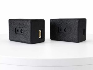
The HM-LD1 compact 3D dToF LiDAR is a solid-state depth-sensing module designed for robot, UAV, and autonomous-system perception. It combines 940 nm VCSEL illumination with SPAD-based direct Time-of-Flight sensing and provides real-time depth and point-cloud data.

| Specification | HM-LD1 Value | Engineering Relevance |
|---|---|---|
| Sensing technology | Solid-state direct Time-of-Flight using SPAD sensing | Produces multi-pixel depth information for 3D perception. |
| Illumination | 940 nm VCSEL | Provides controlled near-infrared illumination for dToF ranging. |
| Depth resolution | 40 × 30 | Provides up to 1,200 spatial depth samples per frame before invalid-point filtering. |
| Indoor ranging capability | 0.5–25 m | Supports room-scale and longer indoor detection within documented conditions. |
| Outdoor ranging capability | 0.2–8 m at 80 klux | Defines outdoor performance under a specified bright-ambient-light condition. |
| Ranging accuracy | ±3 cm | Supports obstacle ranging and geometric perception, subject to test and target conditions. |
| Field of view | 60° horizontal × 45° vertical | Covers a forward-facing three-dimensional perception region. |
| Frame rate | 10 fps | Provides a nominal new frame every 100 ms before host-side processing latency. |
| Interfaces | UART / UDP / UVC | Supports embedded, networked, and USB-oriented integration workflows. |
| Dimensions | 43.5 × 26.5 × 30 mm | Compact form factor for robots, UAVs, and embedded systems. |
| Weight | 28 g | Suitable for platforms with payload constraints. |
| Power consumption | 1.2 W | Must be included in battery, regulator, and thermal budgets. |
| Operating temperature | −20°C to 60°C | Supports a broad range of indoor and outdoor operating environments. |
| Software support | Windows, x86 Linux, and ARM Linux SDK support | Supports development on PCs and common embedded computing architectures. |
View Product Details & Pricing ➔
DTOF Solid-State LiDAR HM-LD1
The DTOF Solid-state LiDAR HM-LD1 product listing describes the same HM-LD1 dToF platform for depth sensing, obstacle avoidance, autonomous navigation, inspection, and robotic-vision development. Its compact housing is listed as 43.5 mm × 30 mm × 26.5 mm, which is the same dimensional set expressed in a different order. The module weighs 28 g and is intended for integration into mobile robots, UAVs, cameras, security systems, and embedded platforms.
The product supports indoor or nighttime ranging from 0.5 m to 25 m and outdoor ranging from 0.2 m to 8 m under the documented outdoor condition. It provides depth images and 3D point-cloud data through UART, UDP, and UVC interfaces. SDK support for x86 Windows, x86 Linux, and ARM Linux helps development teams connect the module to PCs, Raspberry Pi-class computers, Jetson systems, and other embedded platforms.
Application areas include UAV obstacle avoidance, altitude hold and terrain following, robot navigation, SLAM inputs, autofocus, user presence detection, object recognition, volume measurement, zone intrusion monitoring, privacy-conscious human sensing, and gesture recognition. The module is also positioned for outdoor robotics because its stated performance includes operation under bright ambient illumination.
Integration teams should still validate the module using their own target materials, mounting geometry, software pipeline, and sunlight conditions. The product’s compact size, 28 g weight, 1.2 W power consumption, 40 × 30 depth resolution, and 10 fps frame rate make it a practical candidate for prototypes and mobile platforms, but the final application must be checked against detection distance, obstacle size, and total response time.
View Product Details & Pricing ➔
Where the HM-LD1 Fits Best
- ✅ Forward or downward perception on compact UAVs
- ✅ Indoor and outdoor mobile-robot obstacle detection
- ✅ Short-range terrain and clearance sensing
- ✅ Depth-based presence or movement detection
- ✅ Privacy-preserving sensing without conventional RGB imagery
- ✅ Gesture and touchless interaction prototypes
- ✅ Point-cloud and depth-algorithm development on ARM or x86 platforms
The 40 × 30 output is intended for geometric perception rather than high-resolution visual imaging. Integrators should verify whether the target obstacle occupies enough depth pixels at the required detection distance and whether 10 fps satisfies the platform’s maximum speed and stopping-distance requirements.
Download the DTOF SSL HM-LD1 Product Brochure for additional product information and integration planning.
How to Integrate LiDAR into a Robot or Drone
Step 1: Define the Detection Requirement
Begin with the application rather than the sensor. Define minimum and maximum target distance, smallest obstacle dimensions, target materials, maximum platform speed, braking or evasive-maneuver distance, indoor and outdoor illumination, required horizontal and vertical coverage, and acceptable false-negative and false-positive rates.
For example, a slow indoor service robot may need reliable detection of walls, furniture, and people within several meters. A drone may require a forward sensor for obstacle alerts and a downward sensor for clearance. These are different geometric problems even if both use a 3D LiDAR.
Step 2: Choose the Mounting Position
Keep the viewing window unobstructed and avoid placing chassis components inside the field of view. Reduce vibration and structural flex, protect the optical surface from dirt and condensation, and prevent direct reflections from nearby glossy bodywork. Record the sensor’s translation and rotation relative to the robot frame.
For drones, consider propeller intrusion, changing attitude, vibration, payload balance, and the effect of pitch or roll on the observed region. A downward-facing sensor may see the ground at a different angle during acceleration or maneuvering.
Step 3: Design Power and Communications
HM-LD1’s stated power consumption is 1.2 W. Use this as the starting point for battery, regulator, wiring, and thermal calculations, while allowing margin for supply conversion and transient behavior. Verify voltage requirements, grounding, connector pinout, cable length, electromagnetic compatibility, and host bandwidth against official documentation.
Raspberry Pi or ARM Linux computers are suitable for compact prototyping and deployment. NVIDIA Jetson platforms are useful when depth data is combined with accelerated perception. An x86 computer is convenient for development, visualization, logging, and validation. A flight controller or microcontroller may be appropriate when the interface bandwidth and data format match embedded constraints.
Step 4: Acquire and Validate Raw Data
Before building obstacle-detection logic, confirm frame rate, timestamps, units, and invalid-value encoding. Visualize the raw depth image and compare known distances at multiple image positions. Observe behavior on white, gray, black, angled, reflective, and transparent targets. Test indoors, outdoors, and during illumination transitions. Log packet loss, serial errors, stale frames, and invalid-pixel percentages.
Step 5: Calibrate Coordinate Transforms
Intrinsic calibration maps pixels to viewing rays. Extrinsic calibration describes the sensor’s pose on the robot. A mounting error of only a few degrees can shift the apparent position of an obstacle substantially at longer distances. Check axis direction, origin location, units, and timestamp alignment before connecting the point cloud to navigation software.
Step 6: Convert Depth into an Obstacle Representation
A lightweight implementation can divide the depth image into left, center, and right zones and track the nearest valid depth in each region. A more advanced implementation converts pixels into 3D points, removes the floor, and clusters nearby points. Navigation systems may insert transformed points into a voxel map or local costmap.
Zone monitoring is simple and computationally efficient. Point-cloud clustering provides more geometry. Occupancy mapping supports navigation planners but requires localization, timestamp management, and careful treatment of moving objects.
Step 7: Integrate with ROS or ROS2
ROS or ROS2 integration generally requires a device driver or SDK wrapper, depth-image publication, point-cloud publication, calibration information, and TF transforms between the sensor, robot base, odometry, and map frames. Standard message types may include sensor_msgs/Image and sensor_msgs/PointCloud2.
Developers should also configure timestamps, ROS2 quality-of-service settings, visualization in RViz, and costmap or voxel-layer behavior. Do not assume that every product has an official ROS package. Instead, verify whether the SDK data can be wrapped into standard messages and whether examples are available for the target operating system.
Step 8: Implement Fail-Safe Behavior
The host application should detect missing frames, stale timestamps, excessive invalid pixels, blocked optics, out-of-range targets, communication failures, and sensor diagnostic warnings. It should define what the robot or drone does when valid depth is temporarily unavailable.
LiDAR is one component in a safety architecture. Applications involving people or hazardous machinery require appropriate certified safety devices and a system-level risk assessment. A development sensor should not automatically be treated as a certified safety-rated protective device.
LiDAR measures local geometry but does not automatically provide globally referenced position. Outdoor autonomous systems may combine LiDAR with inertial sensors, odometry, cameras, or GNSS components from positioning specialists such as Unicore Communications. Sensor fusion should account for each sensor’s frame, timestamp, update rate, and failure modes.
Practical LiDAR Application Workflows
Mobile-Robot Obstacle Avoidance
A typical workflow acquires a depth frame, removes invalid and floor points, transforms the remaining points to the robot frame, keeps points inside the robot’s future swept path, estimates the nearest obstacle distance, and applies warning, slowdown, or stop thresholds. Tracking persistence across several frames can reduce noise-triggered stops, while excessive smoothing can delay a genuine response.
The robot should account for its footprint, turning radius, current velocity, commanded velocity, and braking distance. A point that is safe for a stationary robot may be unsafe for a fast-moving platform. The planner should also consider gaps between depth samples, because a low-resolution sensor may not observe every narrow object.
UAV Perception and Clearance
UAV integration places strong emphasis on weight, power, vibration, attitude, and rapidly changing geometry. A forward-facing HM-LD1 can provide depth data for obstacle alerts, while a downward-facing installation can support terrain or clearance perception. The use case must fit the documented range and update rate.
Flight-critical integration requires extensive testing and should not rely solely on one sensor. Developers should examine sensor behavior during pitch, roll, vibration, rapid sunlight changes, and temporary data loss. The flight controller also needs a clear policy for invalid or stale measurements.
Privacy-Preserving Human Sensing
Depth maps can support presence detection, occupancy measurement, posture analysis, movement tracking, and human activity recognition without recording a conventional RGB image. This can be useful in human-centric environments where minimizing identifiable image data is desirable.
Depth information can still be sensitive. Organizations should define retention, access, encryption, and processing policies. In many deployments, edge processing can reduce the need to transmit or store raw depth frames.
Gesture Recognition
Gesture recognition commonly follows the sequence of depth acquisition, hand-region segmentation, background removal, three-dimensional feature extraction, and temporal classification. Practical performance depends on hand distance, pixel coverage, motion speed, background geometry, and model training. Ranging accuracy alone does not guarantee reliable finger-level recognition.
LiDAR Selection and Validation Checklist
Sensor Selection
- ✅ Is the stated range tested under conditions comparable to the application?
- ✅ Is outdoor range qualified by ambient illumination?
- ✅ Is the minimum range compatible with the mounting position?
- ✅ Does the field of view cover the robot’s swept path?
- ✅ Can the smallest obstacle occupy enough depth samples?
- ✅ Is frame rate sufficient for maximum platform speed?
- ✅ Are size, weight, power, and operating temperature acceptable?
Integration
- ⚙️ Does the host support UART, UDP, or UVC as required?
- ⚙️ Is an SDK available for the host operating system and architecture?
- ⚙️ Are depth units, invalid values, and timestamps documented?
- ⚙️ Can depth data be converted using calibrated intrinsics?
- ⚙️ Is the sensor-to-robot transform known?
- ⚙️ Is bandwidth sufficient for continuous operation?
Environmental Validation
- ✅ Test white, gray, black, reflective, transparent, and angled targets.
- ✅ Test direct sun, shade, indoor lighting, and illumination transitions.
- ✅ Test rain, dust, fog, or protective-window contamination if applicable.
- ✅ Test nearby active infrared sensors.
- ✅ Test vibration and temperature extremes.
- ✅ Verify startup, disconnect, reconnection, and stale-data behavior.
System Safety
- ⚙️ Define what happens when no valid depth is available.
- ⚙️ Add conservative distance margins.
- ⚙️ Log data during failures.
- ⚙️ Validate complete perception-to-actuation latency.
- ⚙️ Use redundant or certified sensing where required by the risk assessment.
Frequently Asked Questions About LiDAR Sensors
Can LiDAR sensors work reliably outdoors in bright sunlight?
How accurate are LiDAR sensors, and can they provide both distance and 3D data?
Is LiDAR difficult to integrate with Raspberry Pi, Jetson, ROS, or a flight controller?
What is the difference between LiDAR and a camera?
What is the difference between direct and indirect Time-of-Flight?
How does a LiDAR sensor create a point cloud?
Is a 40 × 30 depth resolution enough for obstacle avoidance?
Is a 10 fps LiDAR frame rate fast enough for a moving robot or drone?
How do black, reflective, or transparent objects affect LiDAR?
Can a 3D dToF LiDAR be used for SLAM?
Are infrared LiDAR sensors safe for human eyes?
Does depth-only LiDAR improve privacy?
Choosing LiDAR for a Real System
LiDAR sensors work by transmitting controlled light, measuring the returning signal, and converting that measurement into distance. In direct Time-of-Flight systems, the core calculation is based on the round-trip travel time of light. Multi-pixel dToF sensors repeat this process across a field of view to produce depth maps and point clouds that robots can use for obstacle detection, local navigation, terrain sensing, presence detection, and touchless interaction.
Successful integration requires more than checking maximum range. Engineers must evaluate sunlight conditions, target reflectivity, minimum range, field of view, spatial resolution, frame rate, total latency, interfaces, calibration, mounting, and failure behavior. The HM-LD1 provides a compact reference platform with 40 × 30 depth resolution, ±3 cm accuracy, a 60° × 45° FOV, indoor ranging to 25 m, outdoor ranging to 8 m at 80 klux, and UART, UDP, and UVC connectivity.
📚 References & Further Reading
- 📘 Industry Standard: Unicore Communications
- 📘 Related Guide: LiDAR Scanning for Robotics and Drones
- 📘 Related Guide: Depth Sensors for Obstacle Avoidance
- 📘 Related Guide: How Does LiDAR Work?
- 📘 Product Reference: HM-LD1 Compact 3D dToF LiDAR
- 📘 Product Brochure: DTOF SSL HM-LD1 Product Brochure






